

Panasonic SC-PT865, SC-PT560, SC-PT565 User Manual
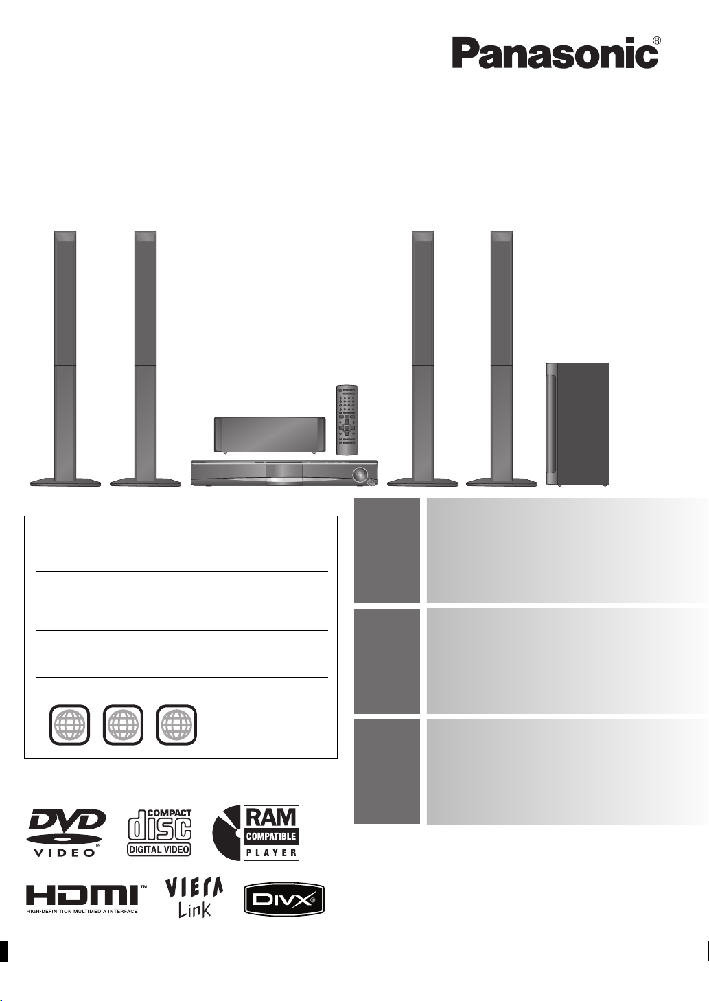
The illustration shows SC-PT565.
The illustrations shown may differ from your unit.
Operating Instructions
DVD Home Theater Sound System
Model No. SC-PT560
SC-PT565
SC-PT865
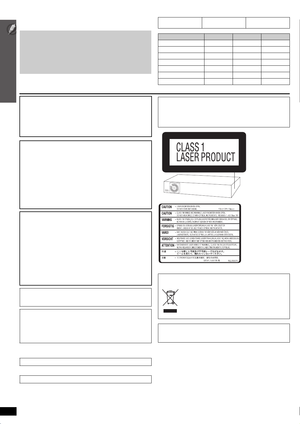
Region number
The player plays DVD-Video marked with labels containing the
region number or “ALL”.
Region Number
The Middle East, South Africa, Saudi Arabia and
Kuwait
Southeast Asia and Thailand 3
Australia and N.Z. 4
Example: [The[Middle[East,[South[Africa,]Saudi[Arabia]and]Kuwait]
2
2 ALL
3
5
2
VIERA Link compatible
Enjoy high-quality picture and linked
30
operations with your VIERA TV.
Sound enhancement
options
32
Surround Enhancer, Dolby Pro
Logic II, and more.
iPod connectivity
Enjoy iPod music through the
35
Before connecting, operating or adjusting this product, please read
the instructions completely.
Please keep this manual for future reference.
speakers, view iPod photos/videos
on the TV.
[GC] [GS] [GCS] [GCT] [GN]
RQTX0099-1B
Dear customer
Thank you for purchasing this product. For optimum performance and
safety, please read these instructions carefully.
Indicates features applicable to:
[PT560] :SC-PT560
only
[PT565] :SC-PT565
only
[PT865] :SC-PT865
only
≥ These operating instructions are applicable to models
SC-PT560, SC-PT565 and SC-PT865 for a variety of regions.
≥ Unless otherwise indicated, illustrations in these operating
instructions are of
Saudi Arabia and Kuwait
≥ Operations in these instructions are described mainly with the
remote control, but you can perform the operations on the main
unit if the controls are the same.
SC-PT565 for the Middle East, South Africa,
.
CAUTION!
THIS PRODUCT UTILIZES A LASER.
USE OF CONTROLS OR ADJUSTMENTS OR PERFORMANCE OF
PROCEDURES OTHER THAN THOSE SPECIFIED HEREIN MAY
RESULT IN HAZARDOUS RADIATION EXPOSURE.
DO NOT OPEN COVERS AND DO NOT REPAIR YOURSELF.
REFER SERVICING TO QUALIFIED PERSONNEL.
WARNING:
TO REDUCE THE RISK OF FIRE, ELECTRIC SHOCK
OR PRODUCT DAMAGE,
≥
DO NOT EXPOSE THIS APPARATUS TO RAIN,
MOISTURE, DRIPPING OR SPLASHING AND THAT
NO OBJECTS FILLED WITH LIQUIDS, SUCH AS
VASES, SHALL BE PLACED ON THE APPARATUS.
≥
USE ONLY THE RECOMMENDED ACCESSORIES.
≥
DO NOT REMOVE THE COVER (OR BACK); THERE
ARE NO USER SERVICEABLE PARTS INSIDE. REFER
SERVICING TO QUALIFIED SERVICE PERSONNEL.
System SC-PT560 SC-PT565 SC-PT865
Main unit SA-PT560 SA-PT560 SA-PT860
Front speakers SB-HF560 SB-HF560 SB-HF860
Center speaker SB-HC560 SB-HC560 SB-HC560
Surround speakers SB-HS560 SB-HS860 SB-HS861
Subwoofer SB-HW560 SB-HW560 SB-HW860
Digital transmitter — — SH-FX65T
Wireless system — — SE-FX65A
Except [Australia]and]N.Z.]
CAUTION:
The AC voltage is different according to the area.
Be sure to set the proper voltage in your area before use.
(For details, please refer to page 12.)
(Side of product)
CAUTION!
≥ DO NOT INSTALL OR PLACE THIS UNIT IN A BOOKCASE,
BUILT-IN CABINET OR IN ANOTHER CONFINED SPACE.
ENSURE THE UNIT IS WELL VENTILATED. TO PREVENT RISK
OF ELECTRIC SHOCK OR FIRE HAZARD DUE TO
OVERHEATING, ENSURE THAT CURTAINS AND ANY OTHER
MATERIALS DO NOT OBSTRUCT THE VENTILATION VENTS.
≥ DO NOT OBSTRUCT THE UNIT’S VENTILATION OPENINGS
WITH NEWSPAPERS, TABLECLOTHS, CURTAINS, AND
SIMILAR ITEMS.
≥ DO NOT PLACE SOURCES OF NAKED FLAMES, SUCH AS
LIGHTED CANDLES, ON THE UNIT.
≥ DISPOSE OF BATTERIES IN AN ENVIRONMENTALLY
FRIENDLY MANNER.
This product may receive radio interference caused by mobile
telephones during use. If such interference is apparent, please
increase separation between the product and the mobile telephone.
The socket outlet shall be installed near the equipment and easily
accessible.
The mains plug of the power supply cord shall remain readily
operable.
To completely disconnect this apparatus from the AC Mains,
disconnect the power supply cord plug from AC receptacle.
[Southeast]Asia,[Thailand,[The[Middle[East,[South[Africa,]
[Saudi[Arabia[and[Kuwait]
THIS UNIT IS INTENDED FOR USE IN TROPICAL CLIMATES.
[Australia]and]N.Z.]
THIS UNIT IS INTENDED FOR USE IN MODERATE CLIMATES.
(Inside of product)
-If you see this symbolInformation on Disposal in other Countries outside the
European Union
This symbol is only valid in the European
Union.
If you wish to discard this product, please
contact your local authorities or dealer and ask
for the correct method of disposal.
[PT865]
For wireless system
Product Identification Marking is located on the bottom of unit.
RQTX0099
2
TABLE OF CONTENTS
Getting
Started
Playing
Discs
Other
Operations
Caution for AC Mains Lead. . . . . . . . . . . . . . . . 4
Safety precaution . . . . . . . . . . . . . . . . . . . . . . . 4
Accessories . . . . . . . . . . . . . . . . . . . . . . . . . . . . 5
Simple Setup
step 1 Assembling the speakers . . . . . . . . . . 6
step 2 Positioning . . . . . . . . . . . . . . . . . . . . . . 7
Speaker installation options. . . . . . . . . . . . . 8
step 3 Cable connections. . . . . . . . . . . . . . . . 9
Speaker connections . . . . . . . . . . . . . . . . . . 9
Audio and video connections. . . . . . . . . . . 10
Radio antenna connections . . . . . . . . . . . . 11
Basic play. . . . . . . . . . . . . . . . . . . . . . . . . . . . . 18
Using the main unit . . . . . . . . . . . . . . . . . . . . . . . . . . . 18
Using the remote control . . . . . . . . . . . . . . . . . . . . . . . 19
Other playback functions . . . . . . . . . . . . . . . . 20
Repeat play . . . . . . . . . . . . . . . . . . . . . . . . . . . . . . . . . 20
Program and Random play . . . . . . . . . . . . . . . . . . . . . 20
Enjoying the radio . . . . . . . . . . . . . . . . . . . . . . 28
Manual tuning . . . . . . . . . . . . . . . . . . . . . . . . . . . . . . . 28
Enjoying Karaoke
(except ]Australia[and[N.Z.]) . . . . . . . . . . . . . . . 29
Using Karaoke mode. . . . . . . . . . . . . . . . . . . . . . . . 29
Adding echo effect . . . . . . . . . . . . . . . . . . . . . . . . . 29
Using the VIERA Link “HDAVI ControlTM” . . . 30
One touch play . . . . . . . . . . . . . . . . . . . . . . . . . . . . . . 30
Auto input switching. . . . . . . . . . . . . . . . . . . . . . . . . . . 30
Power off link . . . . . . . . . . . . . . . . . . . . . . . . . . . . . . . . 30
Speaker control . . . . . . . . . . . . . . . . . . . . . . . . . . . . . . 31
VIERA Link Control only with TV’s remote control
[for “HDAVI Control 2 (or later)”]. . . . . . . . . . . . . . . . 31
step 4 Digital transmitter
connection [PT865] . . . . . . . . . . . . . 12
step 5 AC mains lead connection . . . . . . . . 12
step 6 Preparing the remote control . . . . . . 13
step 7 Performing QUICK SETUP . . . . . . . . 14
step 8 Presetting the radio stations . . . . . . 15
Presetting stations automatically. . . . . . . . .15
Confirming the preset channels. . . . . . . . . .15
Control reference guide . . . . . . . . . . . . . . . . . 16
Utilising the START menu . . . . . . . . . . . . . . . 17
Using navigation menus . . . . . . . . . . . . . . . . . 21
Playing data discs . . . . . . . . . . . . . . . . . . . . . . . . . . . . .21
Playing RAM and DVD-R/ -RW (DVD-VR) discs . . . . .21
Using on-screen menus . . . . . . . . . . . . . . . . . 22
About DivX VOD contents . . . . . . . . . . . . . . . 24
Changing the player settings . . . . . . . . . . . . . 25
Selecting the delay time of the speakers . . . . . . . . . . .28
Using sound effects . . . . . . . . . . . . . . . . . . . . 32
Setting the sound effects . . . . . . . . . . . . . . . . . . . . . . .32
Using Dolby Pro Logic II. . . . . . . . . . . . . . . . . . . . . . . .32
Using Whisper-mode Surround . . . . . . . . . . . . . . . . . .32
Adjusting the subwoofer level . . . . . . . . . . . . . . . . . . . .33
Using Subwoofer Boost . . . . . . . . . . . . . . . . . . . . . . . .33
Adjusting the speaker level . . . . . . . . . . . . . . . . . . . . . .33
Adjusting the Speaker output level automatically:
Auto speaker setup . . . . . . . . . . . . . . . . . . . . . . . . . .33
Operating other equipment . . . . . . . . . . . . . . 34
Enjoying TV audio. . . . . . . . . . . . . . . . . . . . . . . . . . . . .34
Enjoying digital audio . . . . . . . . . . . . . . . . . . . . . . . . . .34
Playing from an USB device . . . . . . . . . . . . . . . . . . . . .34
Using the iPod . . . . . . . . . . . . . . . . . . . . . . . . . . . . . . .35
Reference
Surround
Sound
32
Discs that can be played. . . . . . . . . . . . . . . . . 36
Maintenance. . . . . . . . . . . . . . . . . . . . . . . . . . . 37
Troubleshooting guide . . . . . . . . . . . . . . . . . . 38
TV Audio
34
Glossary . . . . . . . . . . . . . . . . . . . . . . . . . . . . . . 41
Specifications . . . . . . . . . . . . . . . . . . . . . . . . . 42
RQTX0099
3
Caution for AC Mains Lead
(For Saudi Arabia and Kuwait)
(“GS” area code model only)
For your safety, please read the following text carefully.
This appliance is supplied with a moulded three pin mains plug for your
safety and convenience.
A 5-ampere fuse is fitted in this plug.
Should the fuse need to be replaced please ensure that the replacement
fuse has a rating of 5-ampere and that it is approved by ASTA or BSI to
BS1362.
Check for the ASTA mark Ï or the BSI mark Ì on the body of the fuse.
If the plug contains a removable fuse cover you must ensure that it is
refitted when the fuse is replaced.
If you lose the fuse cover the plug must not be used until a replacement
cover is obtained.
A replacement fuse cover can be purchased from your local dealer.
CAUTION!
IF THE FITTED MOULDED PLUG IS UNSUITABLE FOR THE
SOCKET OUTLET IN YOUR HOME THEN THE FUSE SHOULD BE
REMOVED AND THE PLUG CUT OFF AND DISPOSED OF SAFELY.
THERE IS A DANGER OF SEVERE ELECTRICAL SHOCK IF THE
CUT OFF PLUG IS INSERTED INTO ANY 13-AMPERE SOCKET.
If a new plug is to be fitted please observe the wiring code as stated
below.
If in any doubt please consult a qualified electrician.
IMPORTANT
The wires in this mains lead are coloured in accordance with the following
code:
Blue: Neutral, Brown: Live.
As these colours may not correspond with the coloured markings
identifying the terminals in your plug, proceed as follows:
The wire which is coloured Blue must be connected to the terminal which
is marked with the letter N or coloured Black or Blue.
The wire which is coloured Brown must be connected to the terminal
Caution for AC Mains Lead / Safety precaution
which is marked with the letter L or coloured Brown or Red.
WARNING: DO NOT CONNECT EITHER WIRE TO THE
EARTH TERMINAL WHICH IS MARKED WITH THE LETTER
E, BY THE EARTH SYMBOL Ó OR COLOURED GREEN OR
GREEN/YELLOW.
THIS PLUG IS NOT WATERPROOF—KEEP DRY.
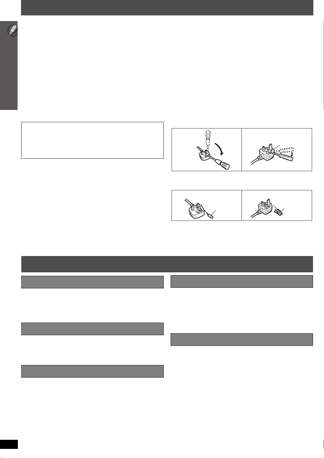
Before use
Remove the connector cover.
How to replace the fuse
The location of the fuse differ according to the type of AC mains plug
(figures A and B). Confirm the AC mains plug fitted and follow the
instructions below.
Illustrations may differ from actual AC mains plug.
1. Open the fuse cover with a screwdriver.
Figure A Figure B
Fuse cover
2. Replace the fuse and close or attach the fuse cover.
Figure A Figure B
Fuse
(5 ampere)
Fuse
(5 ampere)
Safety precaution
Placement
Set the unit up on an even surface away from direct sunlight, high
temperatures, high humidity, and excessive vibration. These conditions
can damage the cabinet and other components, thereby shortening the
unit’s service life.
Do not place heavy items on the unit.
Voltag e
Do not use high voltage power sources. This can overload the unit and
cause a fire.
Do not use a DC power source. Check the source carefully when setting
the unit up on a ship or other places where DC is used.
AC mains lead protection
Ensure the AC mains lead is connected correctly and not damaged. Poor
connection and lead damage can cause fire or electric shock. Do not pull,
bend, or place heavy items on the lead.
Grasp the plug firmly when unplugging the lead. Pulling the AC mains
lead can cause electric shock.
Do not handle the plug with wet hands. This can cause electric shock.
RQTX0099
4
Foreign matter
Do not let metal objects fall inside the unit. This can cause electric shock
or malfunction.
Do not let liquids get into the unit. This can cause electric shock or
malfunction. If this occurs, immediately disconnect the unit from the power
supply and contact your dealer.
Do not spray insecticides onto or into the unit. They contain flammable
gases which can ignite if sprayed into the unit.
Service
Do not attempt to repair this unit by yourself. If sound is interrupted,
indicators fail to light, smoke appears, or any other problem that is not
covered in these instructions occurs, disconnect the AC mains lead and
contact your dealer or an authorized service center. Electric shock or
damage to the unit can occur if the unit is repaired, disassembled or
reconstructed by unqualified persons.
Extend operating life by disconnecting the unit from the power source if it
is not to be used for a long time.
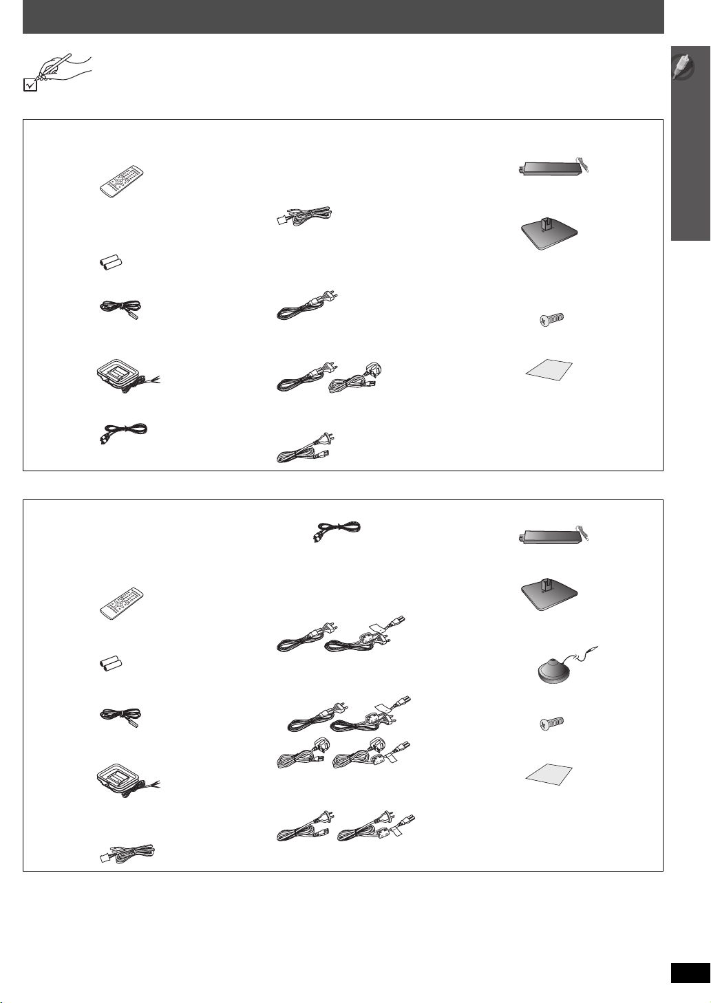
Accessories
Please check and identify the supplied accessories.
[PT565] [PT560]
∏ 1 Remote control
[PT565] (N2QAYB000205)
[PT560] (N2QAYB000255)
∏ Speaker cables
[PT565]
1kshort cable (for center speaker)
[PT560]
1kshort cable (for center speaker)
2klong cable (for surround speakers)
∏ [PT565] 4 Stands
[PT560] 2 Stands
∏ [PT565] 4 Bases
[PT560] 2 Bases
∏ 2 Remote control batteries ∏ AC mains lead
∏ 1 FM indoor antenna ∏ [PT565] 16 Screws
∏ [PT560] 1 AM loop antenna ∏ 1 Sheet of speaker cable stickers
∏ 1 Video cable
[Southeast]Asia,[Thailand,[
[The[Middle[East[and[South[Africa]
1kAC mains lead
[PT560] 8 Screws
[Saudi[Arabia[and[Kuwait]
2kAC mains lead
[Australia]and]N.Z.]
1kAC mains lead
[PT865]
∏ 1 Remote control
[Southeast]Asia,[Thailand,[The[Middle[East,[
[South[Africa,[Saudi[Arabia[and[Kuwait]
(N2QAYB000209)
[Australia]and]N.Z.]
(N2QAYB000256)
∏ 2 Remote control batteries
∏ 1 Video cable ∏ 4 Stands
∏ AC mains lead
[Southeast]Asia,[Thailand,[
[The[Middle[East[and[South[Africa]
2kAC mains lead
∏ 4 Bases
∏ 1 Auto speaker setup microphone
Accessories
[Saudi[Arabia[and[Kuwait]
∏ 1 FM indoor antenna
∏ [Australia]and]N.Z.] 1 AM loop antenna ∏ 1 Sheet of speaker cable stickers
∏ Speaker cables
1kshort cable (for center speaker)
4kAC mains lead
∏ 16 Screws
[Australia]and]N.Z.]
2kAC mains lead
RQTX0099
5
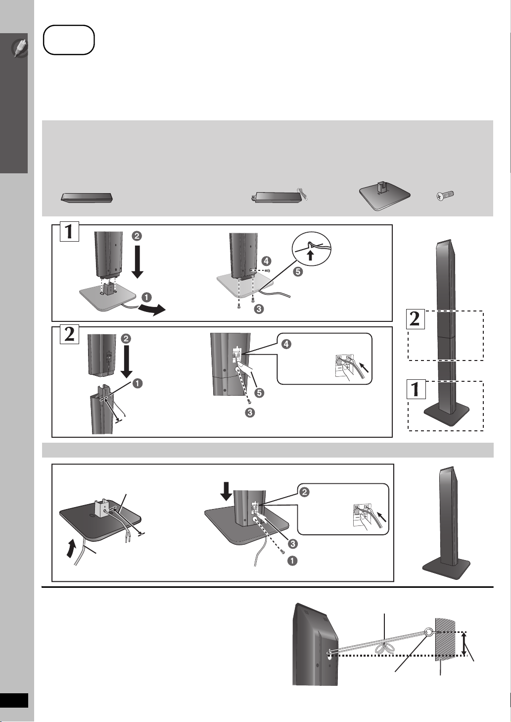
step
1
Assembling the speakers
[PT565] [PT865] Front speakers and surround speakers
[PT560] Front speakers
Preparation
≥ To prevent damage or scratches, lay down a soft cloth and perform assembly on it.
≥ For assembly, use a Phillips-head screwdriver.
≥ For optional wall mount, refer to page 8.
Simple Setup
Make sure you have all the indicated components before starting assembly, setup, and connection.
[PT565] [PT865]
2 Front speakers and 2
Surround speakers
[PT560]
2 Front speakers
[PT565] 4 Stands
≥ 2
k
stands with short cable:
For front speakers
≥ 2
k
stands with long cable:
For surround speakers
[PT865] 4 Stands
≥ 4
k
stands with short cable
Assembling the speakers
[PT560] 2 Stands
≥ 2
k
stands with short cable:
For front speakers
Tighten securely.
[PT565] [PT865]
4 Bases
[PT560]
2 Bases
Slide into the groove.
[PT565] [PT865]
16 screws
[PT560]
8 screws
Position the
cable between
the ridges.
Leave about 90 mm
Speaker assembly option
Thread the speaker cable through
the base.
Leave about 100 mm
You can remove and use the cable from
the stand. To reattach the cable, refer to
page 8.
∫ Preventing the speakers from falling
≥ You will need to obtain the appropriate screw eyes to match the
walls or pillars to which they are going to be fastened.
≥ Consult a qualified housing contractor concerning the
appropriate procedure when attaching to a concrete wall or a
surface that may not have strong enough support. Improper
attachment may result in damage to the wall or speakers.
RQTX0099
6
Attach the speaker.
Insert the wire fully.
i: White
j: Blue
Push!
Press into the groove.
Tighten securely.
Press into the groove.
Tighten securely.
Rear of the speaker
Insert the wire fully.
i: White
j: Blue
Push!
String (not included)
Thread from the wall to the speaker and tie tightly.
Screw eye
(not included)
Wall
Approx.
150 mm
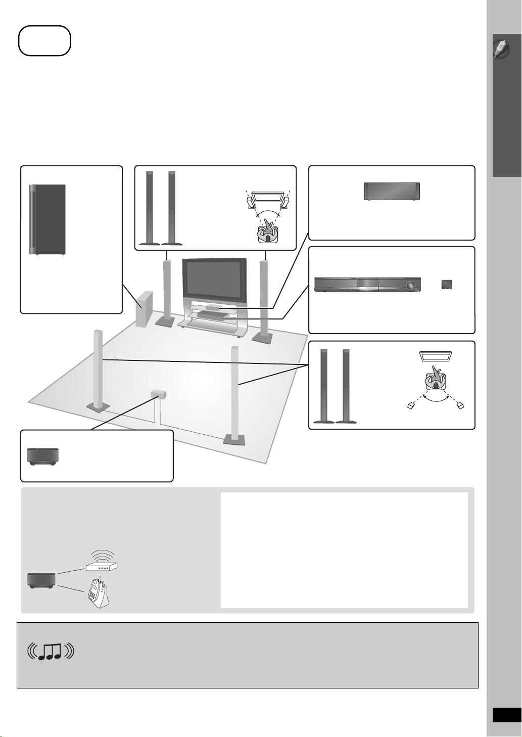
step
2
Positioning
How you set up your speakers can affect the bass and the sound field. Note the following points:
≥ Place speakers on flat secure bases.
≥ Placing speakers too close to floors, walls, and corners can result in excessive bass. Cover walls and windows with thick curtains.
[Note]
Keep your speakers at least 10 mm away from the system for proper ventilation.
Setup example
Place the front, center, and surround speakers at approximately the same distance from the seating position. The angles in the diagram are
approximate.
≥ [PT865]
: Using “Auto speaker setup” (➜ 33) is a convenient way to get the ideal surround sound from your speakers when you are unable to place
them.
Simple Setup
Subwoofer
Place to the right or left of the
TV, on the floor or a sturdy
shelf so that it will not cause
vibration. Leave about 30 cm
from the TV.
[PT865]
Wireless system
Place the wireless system
within approximately 10 m from
the main unit.
Front speakers
60°
Put on a rack or shelf. Vibration caused by the
speaker can disrupt the picture if it is placed
directly on the TV.
Center speaker
Positioning
[PT865]
Main unit
To allow for proper ventilation and to maintain
good airflow around the main unit, position it with
at least 5 cm of space on all sides.
Surround
speakers
e.g.
[PT565]
§
§
Do not use the wireless system or the digital transmitter in a metal cabinet or bookshelf.
Digital
transmitter
120°
[PT865]
To avoid interference, maintain the following
distances between the wireless system and other
electronic devices that use the same radio frequency
(2.4 GHz band).
Wireless
system
Wireless LAN:
approx. 2 m
Cordless phone and
other electronic devices:
approx. 2 m
The wireless system will automatically seek a clear channel if any of these
other devices interfere with its communication. When this happens, the
wireless link indicator (“ [W1] ”) flashes on the main unit, and there is a brief
interruption in audio coming from the surround speakers.
This is the normal operation of the product working to assure the best
possible performance of your home theater system.
If the interference persists, try moving the other devices to another location
outside the range of the wireless system or move the wireless system
nearer to the main unit.
[PT565] [PT560] :
Set your surround free!
Optional Panasonic wireless accessory (example: SH-FX67)
You can enjoy surround speaker sound wirelessly when you use the optional Panasonic wireless accessory (example: SH-FX67).
For details, please refer to the operating instructions for the optional Panasonic wireless accessory.
(Continued on next page)
RQTX0099
7
Notes on speaker use
≥Use only supplied speakers
Using other speakers can damage the unit, and sound quality will be
negatively affected.
≥ You can damage your speakers and shorten their useful life if you play
sound at high levels over extended periods.
≥ Reduce the volume in the following cases to avoid damage:
– When playing distorted sound.
– When the speakers are reverberating due to a record player, noise
from FM broadcasts, or continuous signals from an oscillator, test
Simple Setup
disc, or electronic instrument.
– When adjusting the sound quality.
– When turning the unit on or off.
If irregular colouring occurs on your TV
The center speaker is designed to be used close to a TV, but the picture
may be affected with some TVs and setup combinations.
If this occurs, turn the TV off for about 30 minutes.
The demagnetising function of the TV should correct the problem. If it
persists, move the speakers further away from the TV.
Caution
≥ The main unit and supplied speakers are to be used only as
indicated in this setup. Failure to do so may lead to damage to
the amplifier and/or the speakers, and may result in the risk of
fire. Consult a qualified service person if damage has occurred
or if you experience a sudden change in performance.
≥ Do not attempt to attach these speakers to walls using
methods other than those described in this manual.
Caution
≥ Do not touch the front netted area of the speakers. Hold by the sides.
e.g. Center speaker
DO
NOT
≥ Do not stand on the base.
Be cautious when children
are near.
e.g. Front speaker
DO
DO
NOT
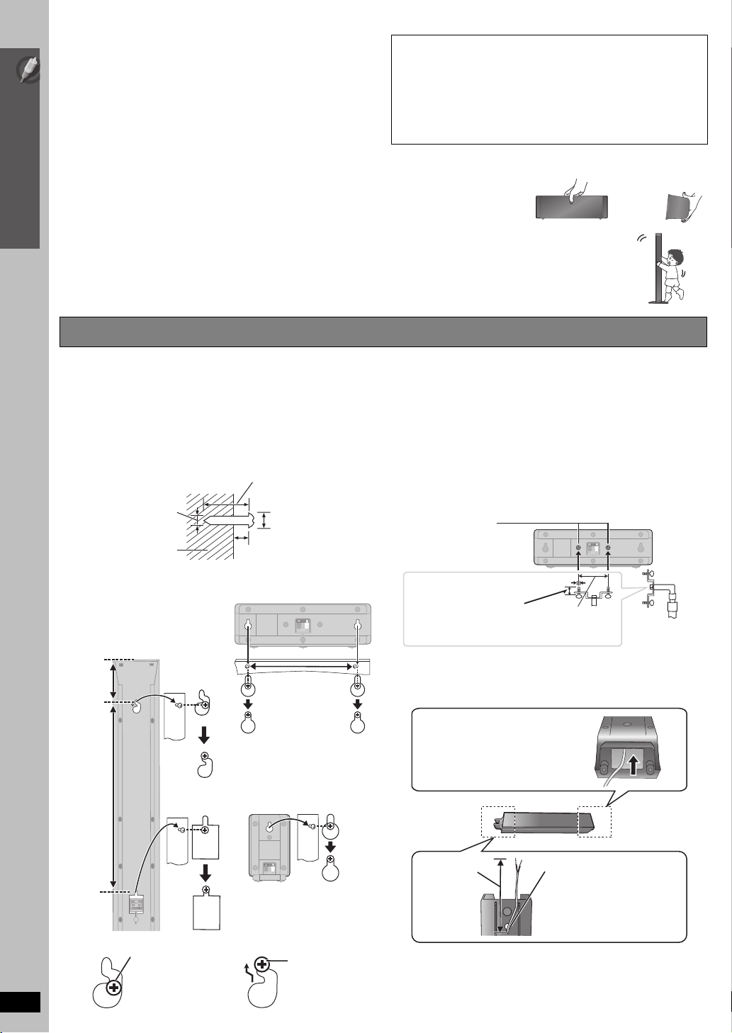
Positioning
Speaker installation options
∫ Attaching to a wall
You can attach all of the speakers (except subwoofer) to a wall.
≥ The wall or pillar on which the speakers are to be attached
should be capable of supporting 10 kg per screw. Consult a
qualified building contractor when attaching the speakers to a
wall. Improper attachment may result in damage to the wall and
speakers.
1 Drive a screw (not included) into the wall.
‰4.0 mm
Wall or pillar
2 Fit the speaker securely onto the screw(s) with the hole(s).
[PT565] [PT865]
speakers
[PT560] Front speakers
Attach to a wall without the base and
the stand
116 mm
Front and surround
At least 30 mm
‰7.0 mm to 9.4 mm
4.0 mm to 6.0 mm
Center speaker
190 mm
∫ Fitting speaker stands (not included)
[PT565] [PT865] Center speaker only
[PT560] Center and surround speakers only
Ensure the stands meet these conditions before purchasing them.
Note the diameter and length of the screws and the distance
between screws as shown in the diagram.
≥ The stands must be able to support over 10 kg.
≥ The stands must be stable even if the speakers are in a high
position.
e.g. Center speaker
Metal screw holes
For attaching to
speaker stands
5.0 mm, pitch 0.8 mm
Plate thickness plus
7.0 mm to 10 mm
60 mm
Speaker stand
(not included)
∫ Reattaching the speaker cable
Insert the cable from
the bottom.
384 mm
e.g.
RQTX0099
NOT
8
In this position,
the speaker will
likely fall if moved
to the left or right.
[PT560] Surround speaker
Move the speaker
so that the screw
DODO
is in this position.
Leave about
90 mm
Pull out the cable
through the hole.
step
3
Cable connections
Turn off all equipment before connection and read the appropriate operating instructions.
Do not connect the AC mains lead until all other connections are complete.
[PT865]
Wireless system
L R
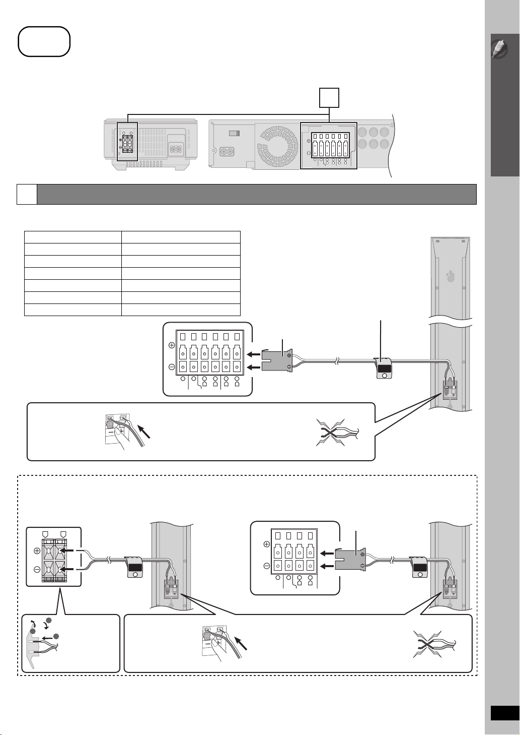
Speaker connections
1
Connecting the speakers to the main unit:
Connect to terminals of the same colour.
Speaker Terminal/connector colour
1 FRONT (L) White
2 FRONT (R) Red
3 SURROUND (L) [PT565] [PT560] Blue
4 SURROUND (R) [PT565] [PT560] Grey
5 CENTER Green
6 SUBWOOFER Purple
[PT565]
Main unit
[PT560]
6 5 2 1 4 3
RLR
CENTERSUBWOOFER FRONT
1
SPEAKERS
6 5 2 1 4 3
CENTERSUBWOOFER FRONT
LRL
R
SURROUND
Main unit
Simple Setup
Cable connections
Speaker cable sticker (included)
Attach the speaker-cable stickers to
make connection easier.
Insert fully.
SURROUND
Lch
L
SURROUND
3
Insert the wire fully.
i: White
j: Blue
Push!
≥ Be careful not to cross (short
circuit) or reverse the polarity of the
speaker wires as doing so may
damage the speakers.
[PT865]
Connecting the speakers to the wireless system:
Wireless system
LR
SURROUND
Rch
4
3
Insert the wires,
1
taking care not
2
to insert beyond
the wire
insulation.
Insert the wire fully.
i: White
j: Blue
Push!
DO
NOT
Main unite.g. Surround speaker (R)
6521
R
L
CENTERSUBWOOFER FRONT
≥ Be careful not to cross (short
circuit) or reverse the polarity of the
speaker wires as doing so may
damage the speakers.
Insert fully.
e.g.
[PT565]
Surround speaker (L)
e.g. Front speaker (L)
FRONT
Lch
1
DO
NOT
(Continued on next page)
RQTX0099
9
step
3
Cable connections
Simple Setup
2
Basic setup example
Cable connections
Other video connections for improved picture quality
The illustration shows
SC-PT560 for [Australia[and]N.Z.]
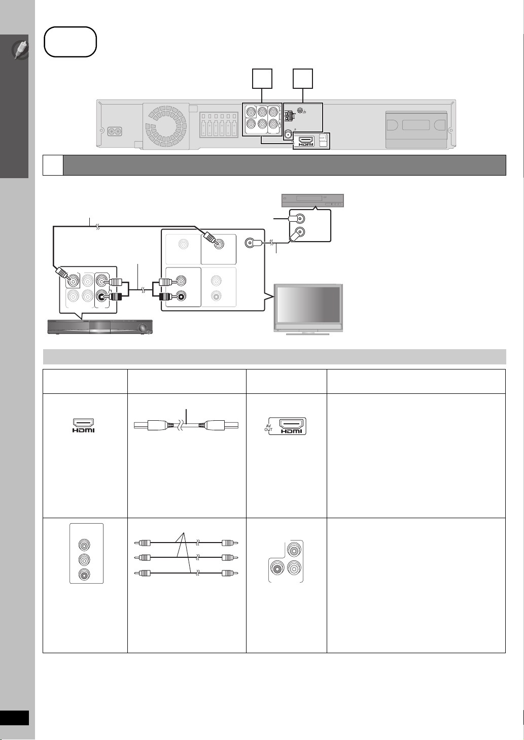
Audio and video connections
Video cable
(included)
VIDEO OUT
R
P
PBY
COMPONENT VIDEO OUT
Audio cable
(not included)
L
R
AUX
To your cable TV service or TV antenna
§
AUDIO OUT
L
R
Main unit
VIDEO INVIDEO OUT
AUDIO IN
2 3
VIDEO OUT
R
P
L
R
PBY
AUX
COMPONENT VIDEO OUT
AM ANT
FM ANT
(75 )
LOOP ANT GND
EXT
LOOP
OPTICAL
IN
Main unit
Set top box or video cassette recorder
(not included)
RF IN
RF OUT
§
RF IN
RF cable
(not included)
L
R
This connection enables you to play audio from
your TV, set top box or video cassette recorder
through your home theater system (➜ 34,
Enjoying TV audio).
TV (not included)
10
TV terminal
Cable required
(not included)
HDMI cable
Main unit terminal Features
[\\\\\\\\\\\HDMI\\\\\\\\\\\]
This connection provides the best picture quality.
≥
Set “
≥ Set “VIDEO FORMAT” in Menu 5 (HDMI) (➜ 23).
AV IN
[Note]
≥ Non-HDMI-compliant cables
cannot be utilized.
≥ It is recommended that you use
Panasonic’s HDMI cable.
Recommended part number:
RP-CDHG15 (1.5 m),
RP-CDHG30 (3.0 m),
VIERA Link “HDAVI Control”
If your Panasonic TV is
operate it synchronising with home theater operations
or vice versa (➜ 30, Using the VIERA Link “HDAVI
Control
≥ Make the extra audio connection (➜ 11) when you
use
RP-CDHG50 (5.0 m), etc.
COMPONENT
VIDEO IN
PR
PB
Y
Panasonic televisions
with 576/50i·50p, 480/
Video cables
[COMPONENT_VIDEO_OUT]
P
R
P
B
Y
COMPONENT VIDEO OUT
≥ Connect to terminals
of the same colour.
This connection provides a much purer picture than the
VIDEO OUT terminal.
To enjoy progressive video
≥ Connect to a progressive output compatible
television.
– Set “VIDEO OUT (I/P)” in “VIDEO” menu to
“PROGRESSIVE” and then follow the instructions
on the menu screen (➜ 26, “VIDEO” menu).
60i·60p input terminals
are progressive
compatible. Consult the
manufacturer if you have
another brand of TV.
[Note]
≥ Do not make the video connections through the video cassette recorder.
Due to copy guard protection, the picture may not be displayed properly.
≥ Only one video connection is required. Choose one of the video connections above depending on your TV.
RQTX0099
VIDEO PRIORITY
TM
”).
VIERA Link “
HDAVI Control” function.
” to “ON” (
VIERA Link
➜ 27, “HDMI” menu
compatible, you can
).
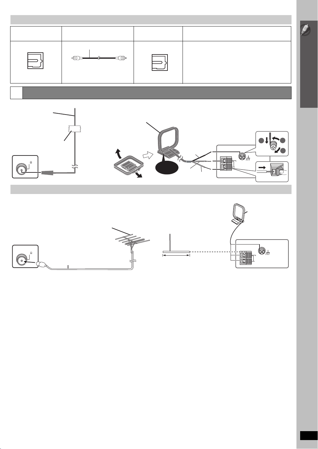
Other audio connections
TV or external
equipment terminal
OPTICAL OUT
Radio antenna connections
3
FM indoor antenna
(included)
Affix this end of the antenna
where reception is best.
Adhesive tape
Main unit
FM ANT
(75 )
Cable required
(not included)
Optical digital audio cable
≥ Do not bend sharply when
connecting.
[Australia]and]N.Z.]
AM loop antenna
(included)
Stand the antenna up on
its base.
Place the antenna where
reception is best.
Using an outdoor antenna (optional)
Use outdoor antenna if radio reception is poor.
≥ Disconnect the antenna when the unit is not in use.
≥ Do not use the outdoor antenna during an electrical storm.
FM outdoor antenna
[Using a TV antenna (not included)]
≥ The antenna should be installed by a
Main unit
competent technician.
FM ANT
(75 )
75 ≠ coaxial cable
(not included)
Main unit terminal Features
[\\\\\\OPTICAL\IN\\\\\\]
OPTICAL
IN
Click!
[Australia]and]N.Z.]
AM outdoor antenna
[Using a vinyl wire (not included)]
Run a piece of vinyl wire horizontally
across a window or other convenient
location.
This unit can decode the surround signals received
through the set top box, digital broadcasting or satellite
broadcasts. Refer to your equipment’s operating
instructions for details. Only Dolby Digital and PCM can
be played with this connection.
≥ After making this connection, make settings to suit the
type of audio from your digital equipment
Main unit
5 to 12 m
Red
Black
White
AM ANT
EXT
LOOP
Main unit
(
➜ 34
2
LOOP ANT GND
Leave the AM loop
antenna connected.
AM ANT
EXT
LOOP
).
1
3
Push!
LOOP ANT GND
Simple Setup
Cable connections
RQTX0099
11
step
TRANSMITTER
DIGITAL
PUSHPUSH
PUSHPUSH
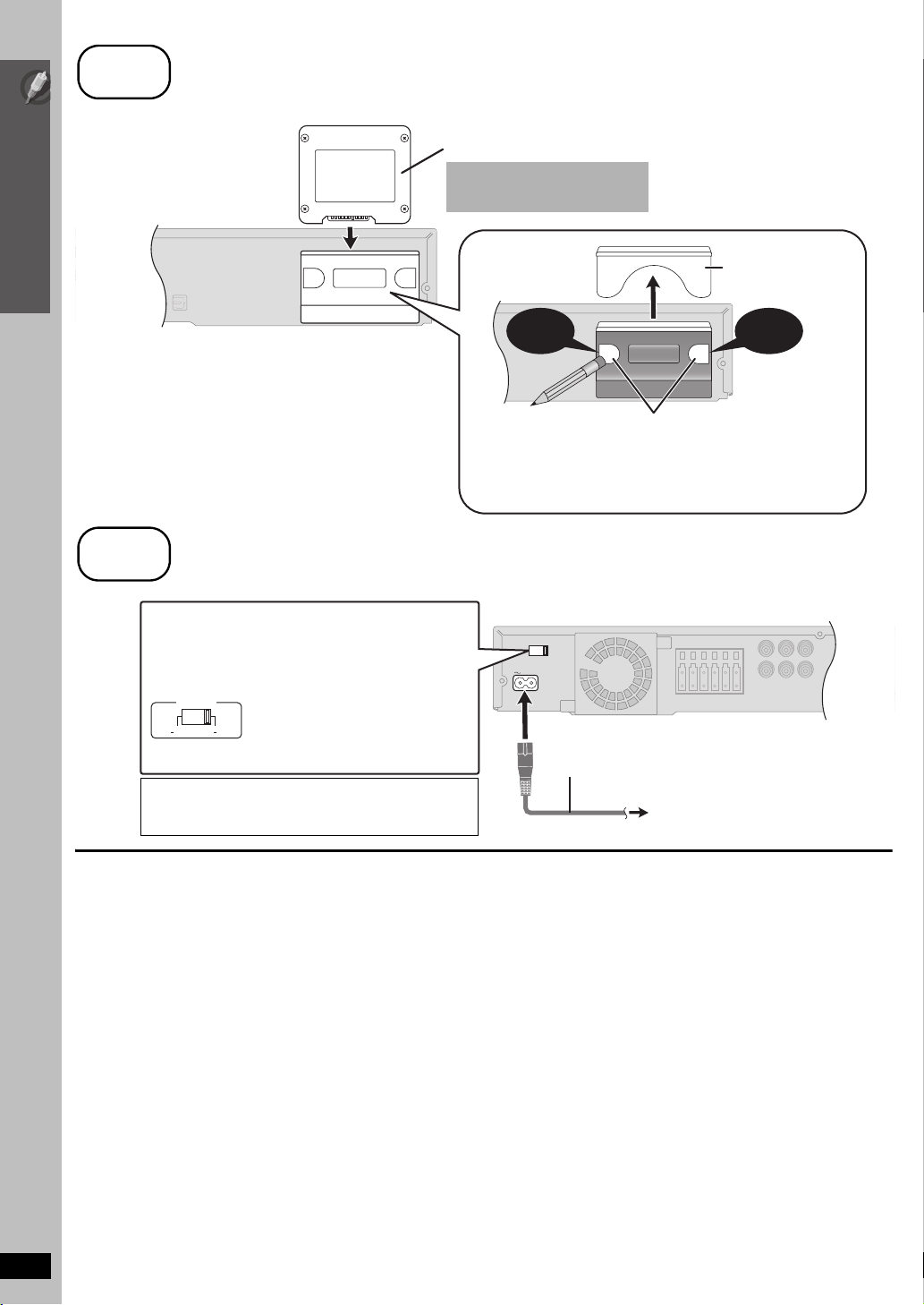
4
Digital transmitter connection [PT865]
Digital transmitter
Insert fully until you hear a click.
Do not insert or remove
Simple Setup
while the main unit is on.
/ AC mains lead connection
step
[PT865]
Digital transmitter connection
DIGITAL
TRANSMITTER
Back of the main unit
5
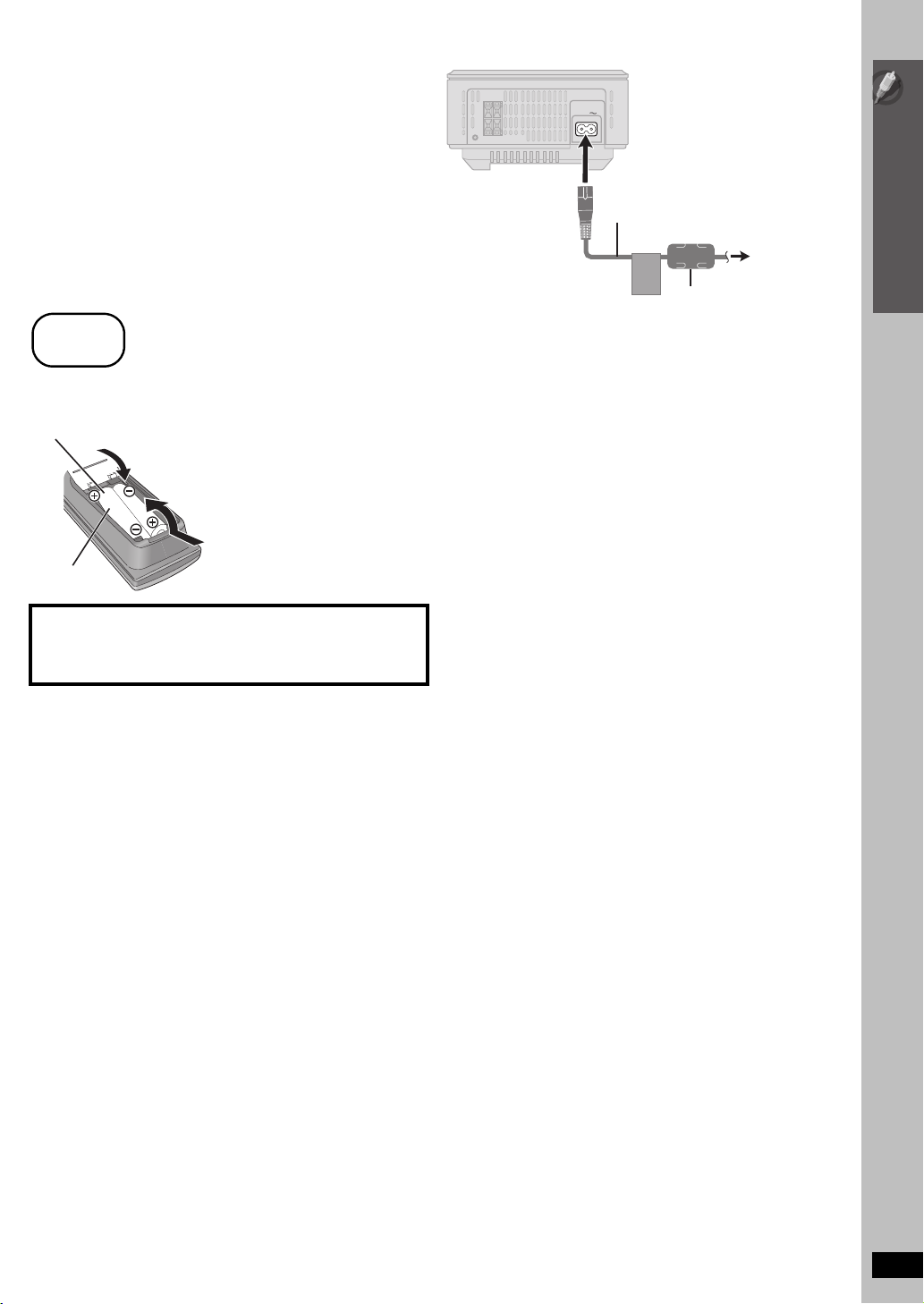
AC mains lead connection
[Southeast]Asia,[Thailand,[The[Middle[East,[South[Africa,]
[Saudi[Arabia[and[Kuwait]
Before connecting the AC mains lead
Set the voltage.
VOLT ADJ
110 127V 220 240V
[Saudi[Arabia[and[Kuwait]
BE SURE TO READ THE CAUTION FOR THE AC
MAINS LEAD ON PAGE 4 BEFORE CONNECTION.
Use a flat-head screwdriver to move
the voltage selector to the appropriate
position for the area in which this
system is used.
[PT565] [PT560]
Push!
You can use the blunt end of a writing instrument
to push here until the cover pops out.
≥ Remove the digital transmitter cover before installing any optional
Panasonic wireless accessory.
≥ Replace the cover when the digital transmitter is not in use.
Main unit
AC IN
AC mains lead
(included)
To household mains socket
Digital transmitter
cover
Push!
12
Conserving power
The main unit consumes a small amount of power, even when it is in
standby mode (approx. 0.4 W). To save power when the unit is not to be
used for a long time, unplug it from the household AC mains socket.
You will need to reset some memory items after plugging in the main
unit.
RQTX0099
[Note]
The included AC mains lead is for use with the main unit only. Do not use
it with other equipment. Also, do not use cords for other equipment with
the main unit.
[PT865] AC mains lead connection for the wireless system:
The wireless system consumes a small amount of power, even
when it is in “OFF” mode (approx. 0.3 W). To save power when the
unit is not to be used for a long time, unplug it from the household
AC mains socket.
An additional AC mains lead is included for use with the wireless
unit and not for use with other equipment. Also, do not use cords
for other equipment with the wireless system.
step
6
Preparing the remote control
AC IN
AC mains lead
(included)
Simple Setup
To household
mains socket
Ferrite core
∫ Batteries
Insert so the poles (i and j) match those in the remote control.
R6/LR6, AA
CAUTION
Danger of explosion if battery is incorrectly replaced. Replace only
with the same or equivalent type recommended by the manufacturer.
Dispose of used batteries according to the manufacturer’s instructions.
≥ Do not use rechargeable type batteries.
≥ Do not heat or expose to flame.
≥ Do not leave the battery(ies) in an automobile exposed to direct
sunlight for a long period of time with doors and windows closed.
Do not:
≥ mix old and new batteries.
≥ use different types at the same time.
≥ take apart or short circuit.
≥ attempt to recharge alkaline or manganese batteries.
≥ use batteries if the covering has been peeled off.
Mishandling of batteries can cause electrolyte leakage which can
severely damage the remote control.
Remove the batteries if the remote control is not going to be used for a
long period of time. Store in a cool, dark place.
∫ Use
Aim at the remote control signal sensor (➜ 17), avoiding obstacles,
at a maximum range of 7 m directly in front of the unit.
AC mains lead connection / Preparing the remote control
RQTX0099
13
13
step
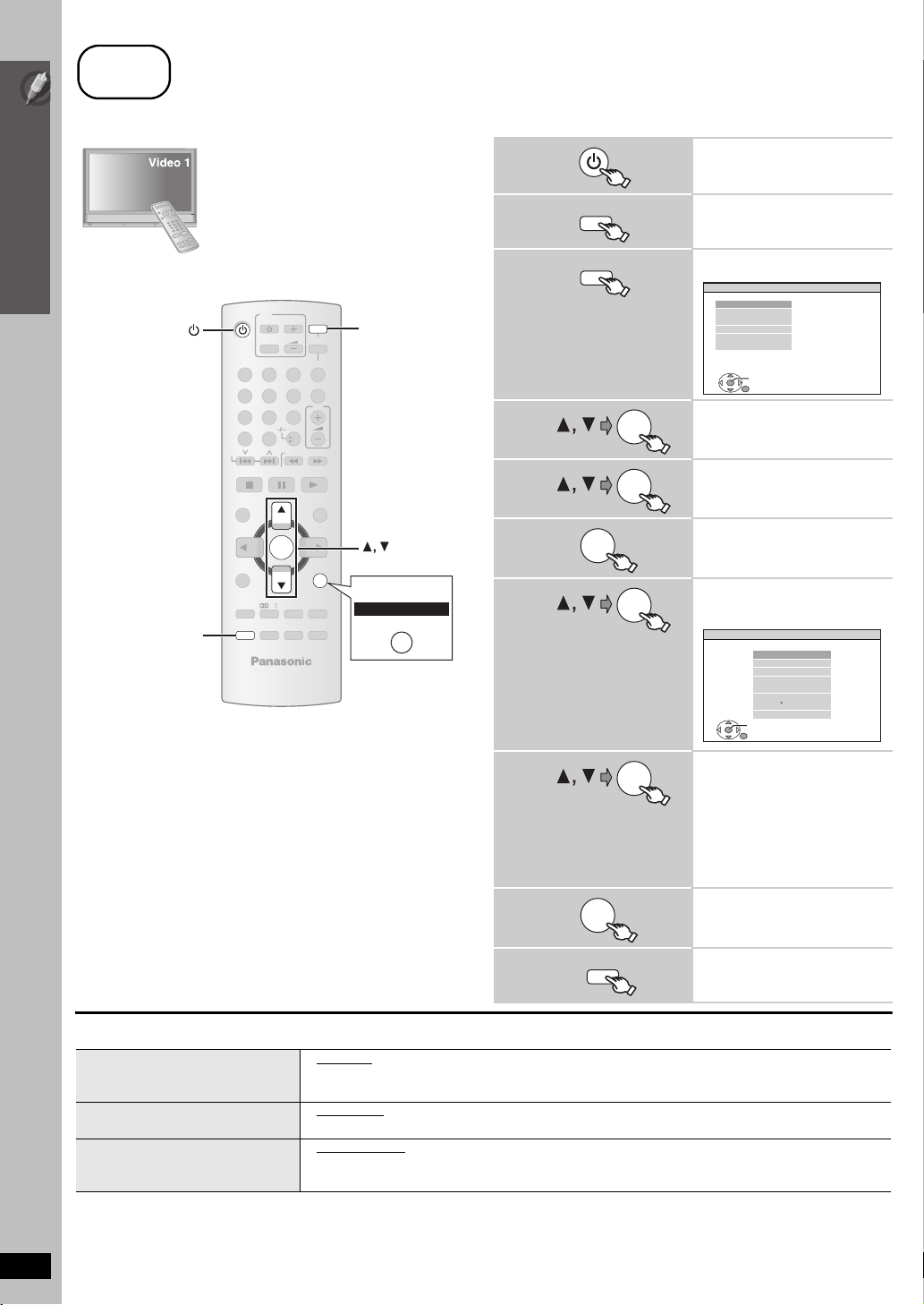
7
Performing QUICK SETUP
The QUICK SETUP screen assists you to make necessary settings.
Preparation
Turn on your TV and select the appropriate
video input mode (e.g. VIDEO 1, AV 1, HDMI,
etc.).
Simple Setup
Performing QUICK SETUP
≥ To change your TV’s video input mode, refer to
its operating instructions.
≥ This remote control can perform some basic
TV operations (➜ 16).
TV
DVD
VOL
TV/AV
iPod/USB
FM/EXT-IN
3
SETUP
12
4
7
CANCEL
SKIP
TOP MENU
DIRECT
NAVIGATOR
MENU
-
FUNCTIONS
-
ECHO
SETUP
PLAY
LIST
5
8 9
0
PL
SOUND
-
W.S.
6
10
SLOW/SEARCH
OK
-
PLAY MODE
-
REPEAT
SUBWOOFER
LEVEL
-
CH SELECT
ONE TOUCH PLAY
VOL
PLAYPAU SESTOP
STAR T
-
RETURN
-
KARAOKE
-
FL DISPLAY
-
SLEEP
MUTING
Australia and N.Z.
DVD
OK
-RETURN
RETURN
1
2
3
4
5
6
7
8
DVD
SETUP
OK
OK
OK
OK
OK
Turn on the unit.
Select “DVD/CD”.
Show the setup menu.
MAIN
DISC
VIDEO
AUDIO
DISPLAY
HDMI
OTHERS
SET
RETURN
EXIT : SETUP
Select “OTHERS”.
Select “QUICK
SETUP”.
Select “SET”.
Select “YES”.
e.g.
OTHERS−QUICK SETUP
SELECT THE MENU LANGUAGE.
SET
RETURN
ENGLISH
FRANÇAIS
ES PAÑOL
DEUTSCH
P
MAGYAR
CESKY
POLSKI
Follow the messages
and make the settings.
≥MENU LANGUAGE
≥TV TYPE
≥TV ASPECT
To return to the previous screen,
press [-RETURN].
([Australia[and[N.Z.]: [RETURN])
9
OK
Finish QUICK SETUP.
14
10
SETUP
Exit.
∫ Details of settings
MENU LANGUAGE
≥ ENGLISH
≥ (Language options)
Choose the language for the
on-screen messages.
TV TYPE
Select to suit the type of TV.
TV ASPECT
Choose the setting to suit your TV
≥ STANDARD
≥ PROJECTION ≥PLASMA
≥ 4:3 PAN&SCAN
≥ 16:9 NORMAL ≥16:9 SHRINK ≥ 16:9 ZOOM
and preference.
≥ Underlined items are the factory settings in the above table.
§
Language options
[The[Middle[East,[South[Africa,[Saudi[Arabia[and[Kuwait]: FRANÇAIS, ESPAÑOL, DEUTSCH, PУCCKИЙ, MAGYAR, ÇESKY and POLSKI
RQTX0099
[Southeast[Asia[and[Thailand]: 繁體中文
[Australia[and[N.Z.]: FRANÇAIS, ESPAÑOL, DEUTSCH, ITALIANO, SVENSKA, NEDERLANDS and POLSKI
§
≥ CRT ≥ LCD
≥ 4:3 LETTERBOX ≥ 4:3 ZOOM
 Loading...