

Page 1

Voice Processing System
Installation Manual
VOICE PROCESSING SYSTEM
POWER
Model No.
KX-TVS50
KX-TVS80
Thank you for purchasing a Panasonic Voice Processing System, Model KX-TVS50/KX-TVS80.
Please read this manual before installing, customizing, or operating the Voice Processing System.
Page 2

2
Page 3

Important Information
SAFETY REQUIREMENTS
• Read all the information c ontained in this manual.
• Follow all product warnings, cautions, and instructions.
• Do not install the unit near water or moisture, heating appliances, or electrical noise
generating devices such as televisions, monitors, fluorescent lamps, or electric motors.
• Install the unit so that the power cord is not obstruc ted in an y way. Do not connect this unit
to an extension cord.
• Mount the unit on a stable wall surface. Do not mount the VPS inside of a separate
enclosure unless it is properly ventilated.
• Keep the unit free of dust, moisture, condensation, high temperature exposure (more than
40 °C{104 °F}) and vibration. Do not expose the unit to direct sunlight.
• Do not insert wires, pins, or any other material into the unit's vent slots or access points.
This could result in electrical shock and serious unit malfunction.
• Do not block the vent slots and openings located on the front and top of the unit.
• This unit is designed to operate at one specific voltage and current setting. The proper
voltage and current required for this unit are listed on the product label.
• This unit is equipped with a 3-wi re gr ound ing plug. The plug will only fit into a grounde d
power outlet. Do not modify this plug in any way. If it cannot be inserted into the outlet,
have the outlet replaced by a licensed electrician.
• Do not overload wall outlets. Overloaded outlets could result in fire and/or electrical shock.
• Do not disassemble this product. Dangerous electrical shock could result. The unit must
only be disassembled and repaired by qualified Panasonic Factory Service Technicians.
• If the unit malfunctions, disconnect the unit from the telephone line and check the line by
reconnecting the telepho ne. If the telephone oper ates properly, have the VPS repaired by an
authorized Panasonic Factory Servicenter.
• Unplug the unit from its power source before cleaning.
• Do not use solvent s, liquid clea ners, wat er , or abrasi v e po wders to cl ean this uni t. Use only
a damp soft cloth for cleaning.
• Handle the unit carefully. Do not drop or otherwise expose the unit to physical shock.
• Unplug and transport the unit to a service technician if the power supply cord is frayed or
damaged, if the cabinet i s cracked or brok en, or when the unit has been exposed to moisture,
has been dropped, or is not otherwise operating properly.
• Do not use the telephone during a lightning storm or to report a gas leak in the vicinity of
the leak.
WARNING
TO PREVENT FIRE OR ELECTRICAL SHOCK, DO NOT EXPOSE THIS UNIT TO
RAIN OR MOISTURE.
Important Information
3
Page 4

When you ship the product
Carefully pack and s end it prepai d, adequately insu red and prefer ably in the o riginal carton.
Attach a postage-paid letter, detailing the symptom, to the outside of the carton. DO NOT
send the product to the Executive or Regional Sales offices. They are NOT equipped to
make repairs.
Product service
Panasonic Factory Servicenters for this product are listed in the servicenter directory.
Consult your authorized Panasonic dealer for detailed instructions.
The serial number of this product may be found on the label affixed to the back of the unit.
You should note the serial number of this unit in the space provided and retain this book as a
permanent record of your purchase to aid in identification in the event of theft.
MODEL NO.:
SERIAL NO.:
For your future reference
DATE OF PURCHASE
NAME OF DEALER
DEALER’S ADDRESS
DEALER’S TEL. NO.
WARNING
THIS UNIT MAY ONLY BE INSTALLED AND SERVED BY QUALIFIED SERVICE
PERSONNEL.
WHEN A FAILURE OCCURS WHICH RESULTS IN THE INTERNAL PARTS
BECOMING ACCESSIBLE, DISCONNECT THE POWER SUPPLY CORD
IMMEDIATELY AND RETURN THIS UNIT TO YOUR DEALER.
4
Important Information
Page 5

DISCONNECT THE TELECOM CONNECTION BEFORE DISCONNECTING THE
POWER CONNECTION PRIOR TO RELOCATING THE EQUIPMENT, AND
RECONNECT THE POWER FIRST.
THIS UNIT IS EQUIPPED WITH AN EARTHING CONTACT PLUG. FOR SAFETY
REASONS THIS PLUG MUST ONLY BE CONNECTED TO AN EARTHING
CONTACT SOCKET WHICH HAS BEEN INSTALLED ACCORDING TO
REGULATIONS.
THE POWER SUPPLY CORD IS USED AS THE MAIN DISCONNECT DEVICE,
ENSURE THAT THE SOCKET-O UTLET IS LOCATED/INSTALLED NEAR THE
EQUIPMENT AND IS EASILY ACCESSIBLE.
CAUTION
Danger of explosion if battery is incorrectly replaced.
Replace only with the same or equivalent type
recommended by the manufacturer.
Dispose of used batteries according to the
manufacturer's instructions.
Note
Before you start setting or changing system parameters, we recommend that you turn off the
Call Progression Mode with the OFLN command. While off, the power LED of the VPS will
flash and the VPS will not answer any incoming calls. After you f i nis h pro gra mmi ng, us e the
ONLN command to turn on the Call Progression Mode (normal operation). Please see
7.2.1 Off-line Set (OFLN) and 7.2.2 On-line Set (ONLN) for more details.
Trademarks
• HyperTerminal is registered trademark of HILGRAEVE, INCORPORATED.
• IBM is registered trademark of International Business Machines Corporation.
• Procomm Plus is registered trademark of DATASTORM TECHNOLOGIES, INC.
• Smartcom is registered trademark of Hayes Microcomputer Products, Inc.
Important Information
5
Page 6

TELEPHONE COMPANY AND F.C.C. REQUIREMENTS AND RESPONSIBILITIES
Notify The Telephone Company
Installation must be performed by a qualified professional installer. If required, provide the
telephone company with the following technical information:
•
The telephone numbers to which the system will be connected
• Make: Panasonic
• Model: KX-TVS50/80
• FCC Registration No.: found on the back of the unit
• Ringer Equivalence No.: 0.4B
• Facility Interface Code: 02LS2
• Service Order Code: 9.0F
• Required Network Interface Jack: RJ11C
Connection to the Telephone Line
The VPS unit must not be connected to coin operated telephone lines. Contact the telephone
company before connecting this unit to a party line.
Telephone Service Problems
The telephone compan y may temporarily d iscontinue se rvice if the VP S causes proble ms with
the telephone networ k. Discontinued service usually occ urs after prior notifi cation. When prior
notification is not practical, the telephone company must:
•
Promptly notify the customer of the temporarily discontinued service.
•
Provide the customer with an opportunity to correct the situation or problem.
•
Inform the customer of the right to bring a complaint to the Federal Communication
Commission pursuant to the procedures set forth in Subpart E of Part 68 of the FCC
Telephone Equipment Rules.
Telephone Network and Terminal Equipment compatibility
Availability of Telephone Interface Information
When requested by the customer, the telephone company must provide the following
information:
•
technical information concerning interface parameters.
•
technical information not specified in FCC rules such as the number of ringers that
can be connected to a particular telephone line.
Changes in Telephone Company Communications Facili ties, Equi pment, Operati ons,
and Procedures
The telephone company may make changes to its communication facilities, equipment,
operations, or procedures, when such action is reasonably required in the operation of its
business, and is not inconsistent with FCC rules (FCC Telephone Equipment Rules, Part
68).
The custom er shall be g iven adequate notic e in writing w hen changes will:
6
Important Information
Page 7

•
render the customer's equipment incompatible with telephone company
communications
•
require modification or alteration of customer terminal equipment
•
materially affect customer terminal equipment use or performance
Adequate notice provides the customer with the opportunity to make any necessary
alterations in order to maintain uninterrupted service.
Note
This equipment has been tested and found to comply with the limits for a Class B
digital device, pursuant to Part 15 of the FCC Rules. These limits are designed to
provide reasonable protection against harmful interference in a residential
installation. This equipment generates, uses and can radiate radio frequency energy
and, if not installed and used in acco rdance wit h the ins tructi ons, may caus e harmful
interference to radio communications. However, there is no guarantee that
interference will not occur in a particular installation. If this equipment does cause
harmful interference to radio or television reception, which can be determined by
turning the equipment off and on, the user is encouraged to try to correct the
interference by one or more of the following measures.
— Reorien t or relocate the receiving antenn a.
— Increase the separation between the equipment and receiver.
— Connect the equipment into an outlet on a circuit different from that to which
the receiver is connected.
— Consult the dealer or an experienced radio/TV technician for help.
Ringer Equivalence No. (REN)
Customers, before connecting terminal equipment to the telephone network, shall upon
request of the Telephone Company , inform the Telephone Company of the particular line(s)
to which such connection is mad e, the F.C.C. registration number (see the l abel on the back
of the unit) and ringer equivalence number (REN) of the registered terminal equipment.
The REN is useful in determining the quantity of devices you may connect to your
telephone line and stil l hav e all of those de vices ring when your telephone nu mber is called.
In most, but n ot all areas, the sum of t he RE N's of all devices conn ec ted t o one line should
not exceed five (5.0). To be certain of the number of de vi ces you may connect to your line,
as determined by the REN, you s hould c ontact your local tele phone co mpan y t o dete rmine
the maximum REN for your calling area.
CAUTION
Any change or modif ication made to the ter minal equipment, not expr essl y appr o ved by the
manufacturer, could void the user's authority to operate this equipment.
When programming and/or making test calls to emergency numbers:
• Remain on the line and briefly explain to the dispatcher the reason for the call.
• Perform these tests during off-peak hours, such as early morning or late evening.
Important Information
7
Page 8

Table of Contents
1 VOICE PROCESSING SYSTEM OVERVIEW
1.1 WHAT THE VPS CAN AND CANNOT DO............................................................14
1.1.1 Why Voice Processing?..............................................................................................14
1.1.2 Basic Operations.........................................................................................................14
1.1.3 VPS Limitations.........................................................................................................15
1.2 SYSTEM ADMINISTRATION, MANAGEMENT, AND USE...............................16
1.2.1 System Administration...............................................................................................16
1.2.2 System Management..................................................................................................16
1.2.3 Subscriber Use............................................................................................................16
1.3 SYSTEM BASICS.......................................................................................................17
1.3.1 General.......................................................................................................................17
1.3.2 System Components...................................................................................................17
1.3.3 Which Phone Systems are Compatible?.....................................................................19
1.3.4 Installer Equipment and Software Requirements.......................................................20
1.3.5 Specifications..............................................................................................................21
1.3.6 Hardware....................................................................................................................21
1.3.7 Flash Memory Expansion Capabilities.......................................................................21
1.3.8 Recommendations for System Configuration.............................................................21
1.4 DIGITAL INTEGRATION.........................................................................................23
1.4.1 General.......................................................................................................................23
1.4.2 APT Integration..........................................................................................................23
1.4.3 Connection Example — APT Integration..................................................................23
1.4.4 DPT Integration..........................................................................................................23
1.4.5 Connection Example — DPT Integration..................................................................24
2 INSTALLATION
2.1 SAFETY PRECAUTIONS.........................................................................................26
2.1.1 Installation..................................................................................................................26
2.1.2 Wiring.........................................................................................................................26
2.2 UNPACKING...............................................................................................................27
2.3 MOUNTING THE VPS ON A WOODEN WALL...................................................28
2.4 FRAME GROUND CONNECTION.........................................................................29
2.5 INSTALLATION STEPS............................................................................................30
2.6 INSTALLING AN OPTIONAL EXPANSION MEMORY CARD (KX-TVS52)..32
2.6.1 General.......................................................................................................................32
2.6.2 Installing the KX-TVS52...........................................................................................32
2.7 CONNECTIONS.........................................................................................................34
2.7.1 Connecting to the PBX...............................................................................................34
2.7.2 Opening the Ferrite Core............................................................................................34
2.7.3 Connection for APT Integration.................................................................................35
2.7.4 Connection for DPT Integration.................................................................................35
2.7.5 Connection for Non-APT/DPT Integration................................................................36
2.8 TERMINAL CONNECTION.....................................................................................37
2.8.1 Requirements for Connecting Programming Terminal..............................................37
2.8.2 Connecting the RS-232C Cable..................................................................................37
2.8.3 EIA (RS-232C) Signals..............................................................................................39
8
Table of Contents
Page 9

3 INTEGRATING THE VPS WITH PANASONIC KX-T PHONE
SYSTEMS
3.1 GUIDELINES FOR INTEGRATION........................................................................42
3.1.1 APT/DPT or Inband Signaling?..................................................................................42
3.1.2 Why Integration is Important......................................................................................42
3.1.3 How the VPS and the PBX Communicate..................................................................42
3.1.4 PBX Requirements for Integration.............................................................................. 43
3.2 PBX PARAMETERS AND PORT SETTINGS .........................................................46
3.2.1 General Guidelines and Definitions............................................................................46
3.2.2 RS-232C Settings........................................................................................................46
3.2.3 Port Settings ................................................................................................................46
3.2.4 PBX Interface Parameters...........................................................................................47
3.3 CONNECTING THE VPS WITH PANASONIC KX-T SERIES PBXs.................50
3.3.1 KX-TVS50/80 Programming for Inband Integration..................................................50
3.3.2 KX-T123211D Software Verification and Programming for Inband Integration....... 51
3.3.3 KX-TA624 Programming for Inband Integration via the Manager's Extension .........53
3.3.4 KX-TD816, KX-TD1232 and KX-TD308 Programming for Inband Integrat ion via the
Manager's Extension..................................................................................................55
3.3.5 KX-TD816, KX-TD1232 Programming for Inband Integration via the Operating and
Maintenance Tool.......................................................................................................55
3.3.6 KX-TD308 Programming for Inband Integration via the Operating and Maintenance
Tool ............................................................................................................................58
4 INTEGRATING THE VPS WITH THE PANASONIC KX-TA
ANALOG PBX AND KX-TD DIGITAL PBX
4.1 GUIDELINES FOR DIGITAL INTEGRATION......................................................64
4.1.1 Why Digital Integration is Important..........................................................................64
4.2 CONNECTING THE KX-TVS50/80 WITH THE PANASONIC KX-TA624........ 66
4.2.1 KX-TA624 Software Verification and Programming for Digital Integration via the
Manager's Extension..................................................................................................66
4.3 CONNECTING THE KX-TVS50/80 WITH THE PANASONIC KX-TD816, KX-
TD1232 AND KX-TD308............................................................................................72
4.3.1 KX-TD1232 Software Verification and Programming for Digital Integration via the
Manager's Extension..................................................................................................72
4.3.2 KX-TD1232 Software Verification and Programming for Digital Integration via the
Operating and Maintenance Tool...............................................................................76
4.3.3 KX-TD308 Software Verification and Programming for Digital Integration via the
Manager's Extension..................................................................................................80
4.4 COMMON DIGITAL INTEGRATION FEATURES AND SETUP PROCEDURES...85
4.4.1 Live Call Screening (LCS) Programming...................................................................85
4.4.2 Live Call Screening Recording Mode Assignment.....................................................85
4.4.3 Live Call Screening Private/Hands-Free Mode Assignment.......................................85
4.4.4 Live Call Screening Button Assignment.....................................................................86
4.4.5 Live Call Screening Cancel Button Assignment.........................................................87
4.4.6 Live Call Screening Password Assignment.................................................................88
4.4.7 Live Call Screening Password Cancellation................................................................88
4.4.8 Live Call Screening Password Control........................................................................88
4.4.9 Two-Way Recording into One's Own Mailbox...........................................................89
4.4.10 Two-Way Recording Button Assignment..................................................................89
Table of Contents
9
Page 10

4.4.11 Two-Way Transfer into Mailbox............................................................................... 90
4.4.12 Two-Way Transfer Button Assignment .................................................................... 90
4.4.13 Voice Mail Transfer Button Assignment.................................................................. 91
5 CUSTOMIZING THE SYSTEM
5.1 STARTING UP............................................................................................................. 94
5.1.1 Before Programming .................................................................................................. 94
5.1.2 Quick Setup ................................................................................................................94
5.1.3 Starting the Quick Setup............................................................................................. 95
5.2 PORT SETTING OPTIONS .................................................................................... 102
5.2.1 Custom Service Setting Example............................................................................. 102
5.2.2 Custom Service Features .......................................................................................... 103
5.2.3 Custom Service Programming............................................................. ......... ......... ... 105
5.2.4 Recording Menus...................................................................................................... 108
5.2.5 Checking Operation............................................................................. ......... ......... ... 108
5.2.6 Voice Mail.................................................................................................................108
5.2.7 Mailbox Groups........................................................................................................ 109
5.2.8 Extension Groups ..................................................................................................... 109
5.2.9 Interview Service...................................................................................................... 110
5.2.10 Automated Attendant.............................................................................................. 111
5.2.11 Department Dialing Service ................................................................................... 111
5.2.12 Operator Service..................................................................................................... 111
5.3 SETTING PORTS..................................................................................................... 112
5.3.1 Port Service Menu.................................................................................................... 112
5.4 AUTOMATED ATTENDANT PARAM ETERS ..................................................... 114
5.4.1 Automated Attendant Menu ..................................................................................... 114
5.4.2 Department Dialing .................................................................................................. 114
5.4.3 Operator's Parameters............................................................................................... 114
5.5 SETTING MAILBOXES.......................................................................................... 117
5.5.1 Mailbox Setting Menu.............................................................................................. 117
5.5.2 Entering a Mailbox................................................................................................... 117
5.5.3 Deleting a Mailbox................................................................................................... 120
5.5.4 Password Reset......................................................................................................... 120
5.5.5 Mailbox Listing ........................................................................................................ 120
5.6 TRAINING THE SUBSCRIBER............................................................................. 121
10
6FINAL SETUP
6.1 MESSAGE MANAGER'S MAILBOX (Mailbox 998)........................................... 124
6.1.1 Accessing the Message Manager's Mailbox............................................................. 124
6.1.2 Main Menu of Message Manager's Service.............................................................. 124
6.1.3 Company Greetings (Enter #6*998,5,1) (KX-TVS80 only).................................... 124
6.1.4 Recording the Company Name (Enter #6*998,5,2) (KX-TVS80 only)................... 125
6.1.5 Custom Service Greetings (Enter #6*998,5,4)......................................................... 125
6.1.6 Customizing User Prompts (Enter #6*998,5,6) ....................................................... 125
6.2 SETTING UP MAILBOXES.................................................................................... 127
6.2.1 Recording Personal Greetings.................................................................................. 127
6.2.2 Recording the Owner's Name................................................................................... 127
6.3 BACKING UP THE SYSTEM................................................................................. 129
Table of Contents
Page 11

7 SYSTEM MAINTENANCE AND TROUBLESHOOTING
7.1 INITIALIZING THE SYSTEM ...............................................................................132
7.2 UTILITY COMMANDS............................................................................................134
7.2.1 Off-line Set (OFLN)..................................................................................................134
7.2.2 On-line Set (ONLN)..................................................................................................135
7.2.3 Set Password (PASS).................................................................................................135
7.2.4 Set Time (TIME).......................................................................................................136
7.2.5 Print Reports at Specified Time (PSET)....................................................................136
7.2.6 Error Log Display (ELOG) .......................................................................................137
7.2.7 Saving the System Data to the Backup Device (SAVE) ............................................139
7.2.8 Loading New or Saved Data to the VPS (LOAD).....................................................141
7.2.9 Print All of the VPS Parameters (GPRN) .................................................................142
7.2.10 Program Version Display (VERS)...........................................................................143
7.2.11 Custom Service Report (CREP)..............................................................................143
7.2.12 Custom Service Menu Access Count Clear (CCLR)..............................................145
7.2.13 Message Waiting Lamp Retry Times (MWL) .........................................................145
7.2.14 Setting Minimum Recording Length (MRL)..........................................................145
7.2.15 Modified Prompt List (MPLT) ................................................................................146
7.2.16 Utility Command List (HELP)................................................................................147
7.2.17 Quick Setup (QSET) ...............................................................................................147
7.2.18 Circuit Condition Display (LMON)........................................................................148
7.2.19 DTMF Information Display (PUTD)......................................................................148
7.3 SYSTEM REPORTS..................................................................................................150
7.3.1 Mailbox Assignments................................................................................................150
7.3.2 COS (Class of Service) Assignments........................................................................151
7.3.3 System Service Report .................... ......... .................................................................152
7.3.4 Call Account Report....................................................................................... ......... ..153
7.3.5 Port Usage Report ........................................................................ ......... ......... ......... ..154
7.3.6 Port Usage Statistics Clear........................................................................................ 154
7.3.7 Flash Memory Usage Report.....................................................................................155
7.3.8 Flash Memory Usage Statistics Clear .......................................................................156
7.3.9 Mailbox Usage Report ..............................................................................................156
7.3.10 Mailbox Usage Statistics Clear...............................................................................157
7.3.11 Fax Call Report ................................................................. ......... ......... ....................158
7.3.12 Fax Call Statistics Clear...................................................................... ....................158
7.4 TROUBLESHOOTING GUIDE...............................................................................160
7.5 SPECIFICATIONS ....................................................................................................162
Table of Contents
Appendix A SYSTEM FEATURES
A1 SYSTEM FEATURES................................................................................................166
Appendix B SYSTEM ADMINISTRATOR'S GUIDE
B1 SYSTEM NAVIGATION............................................................................................192
B2 SYSTEM ADMINISTRATION - MAILBOXES.....................................................196
B3 SYSTEM ADMINISTRATION - SETTING COS (CLASS OF SERVICE)
PARAMETERS.........................................................................................................202
B4 SYSTEM ADMINISTRATION - PORT SERVICE................................................211
B4.1 Port Assignment ........................................................................................................211
B5 SYSTEM ADMINISTRATION - SERVICE SETTINGS.......................................213
11
Page 12

B5.1 Automated Attendant Parameters............................................................................. 213
B5.2 Custom Service......................................................................................................... 220
B5.3 Caller ID Call Routing Parameters........................................................................... 223
B6 SYSTEM ADMINISTRATION - SYSTEM PARAMETER SETTINGS............. 225
B6.1 System Group Assignment ....................................................................................... 225
B6.2 Day Service................................................................................................... ......... ...228
B6.3 Holiday Setting ......................................................................................................... 228
B6.4 Daylight Saving Time (DST).................................................................................... 230
B6.5 Prompt Setting .......................................................................................................... 231
B6.6 System Caller Name Announcement........................................................................ 232
B6.7 Other Parameters....................................................................................................... 234
B7 SYSTEM ADMINISTRATION - HARDWARE SETTINGS ................................ 246
B7.1 RS-232C Parameters................................................................................................. 246
B7.2 Port Setting ............................................................................................................... 247
B7.3 PBX Interface Parameters......................................................................................... 248
Appendix C SYSTEM MANAGER'S GUIDE
C1 ACCESSING THE SYSTEM MANAGER'S MAILBOX...................................... 258
C2 SETTING UP MAILBOXES....................................................................................259
C3 SETTING COS (CLASS OF SERVICE) PARAME TERS.................................... 262
C4 SETTING THE SYSTEM CLOCK......................................................................... 268
C5 CHECKING SYSTEM USAGE (SYSTEM REPORTS)....................................... 269
C6 DELIVERING MESSAGES..................................................................................... 271
C7 CUSTOMIZING THE SYSTEM MANAGER'S MAILBOX................................ 273
C8 LISTENING TO SYSTEM MANAGER MESSAGES........................................... 274
Appendix D MESSAGE MANAGER'S GUIDE
D1 ACCESSING THE MESSAGE MANAGER'S MAILBOX................................... 276
D2 MANAGING THE GENERAL DELIVERY MAILBOX...................................... 277
D3 SETTING UP MESSAGE WAITING NOTIFICATION....................................... 279
D4 CUSTOMIZING THE MESSAGE MANAGER'S MAILBOX............................. 281
D5 SETTING THE SYSTEM CLOCK......................................................................... 283
D6 RECORDING MESSAGES...................................................................................... 284
D7 LIST OF MODIFIABLE PROMPTS...................................................................... 289
Glossary
Index
........................................................................................................................... 335
.................................................................................................................................. 345
12
Table of Contents
Page 13

Section 1
VOICE PROCESSING SYSTEM OVERVIEW
VOICE PROCESSING SYSTEM OVERVIEW
13
Page 14

1.1 WHAT THE VPS CAN AND CANNOT DO
1.1 WHAT THE VPS CAN AND CANNOT DO
1.1.1 Why Voice Processing?
The VPS handles incoming and outgoing calls. When a call comes in, it answers, f orwards to
appropriate e xtensions, takes and stores messag es, and notif ies su bscribers when mes sages are
left. Subscribers may send and transfer messages to other subscribers within the system. The
VPS is easy to use, helping callers through the system with step-by-step voice prompts.
Unlike handwritten messages or those left with answering services, VPS messages are
confidential; they are stored in a mailbox and retrieved only with the subscriber's password.
Other advantages of the VPS are clarity and accuracy, which are commonly lacking with
written messages. The messages come directly from the caller, in the caller's own voice. To
further ensure accuracy, the system allows the sender to correct or change messages before
saving them. Messages can be erased or transferred by the recipient.
1.1.2 Basic Operations
Greeting Callers:
Callers are greeted by a prerecorded message that includes directions for leaving and editing
messages. The VPS can list single-digit numbers for each available extension or mailbox.
Callers who know the e xtension of the person the y wish to reach may dial the e xtension number
at any time. Callers with ro tary phones are t ransferred to a pre-progra mmed destinatio n (which
is often an operator or the General Delivery Mailbox ) to leave a message.
Sending Messages:
Callers can review and edit messages before leaving them in a mailbox. Subscribers can send
messages to an indi vid ual or to s ev eral mailbox es at onc e. The message sender can then v erify
that the other subscriber has received the message.
Receiving Messages:
Subscribers can choose from several different message notification methods. They can be
notified by: message waiting lamp, beeper, or a call from the system to another line. System
programming determines whethe r a subscriber will be notif ied each ti me that a message is left.
(Subscribers can choose to be notified of messages differently depending on the time of day.)
Mailbox parameters determine maximum length and accommodate 5-100 messages. If the
system is connected using Digital Integration, subscribers can press a pre-assigned button to
record conversations in their own mailboxes or other subscribers mailboxes while talking on
the phone. Digital I ntegr ation al so allo ws subscrib ers to sc reen messages as the y are bei ng left
or pick up if they choose to take the call.
14
VOICE PROCESSING SYSTEM OVERVIEW
Page 15

1.1.3 VPS Limitations
The KX-TVS50/80 does not support:
UCD functions
UCD (Uniform Call Distribution) is a service that distributes calls evenly among extensions
and returns to callers to say that all extensions are busy. Calls can be forward ed by the KXTVS50/80 to the KX-TD1232/816/308 floating number of a UCD group. The call then rings
at the next available phone.
The KX-TVS50/80 supports UCD functions with very limited capabilities.
incoming call is forwarded as an intercom path and not a DIL (direct in line), the following
items will not work:
•
time table
•
overflow function
•
DISA message from a DISA card
•
IRNA
1.1 WHAT THE VPS CAN AND CANNOT DO
Because the
Integration with the wrong PBX or with certain K ey Systems pr esents limitati ons to the KXTVS50/80's standard functions.
KX-TVS50/80. The section 1.3.3 Which Phone Systems are Co mpatible? expl ains problems
with compatibility.
W e do not recomme nd these sy stems for i nteg ratio n with the
VOICE PROCESSING SYSTEM OVERVIEW
15
Page 16

1.2 SYSTEM ADMINISTRATION, MANAGEMENT, AND USE
1.2 SYSTEM ADMINISTRATION,
MANAGEMENT, AND USE
1.2.1 System Administration
System Administration is accomplished by the installer and is concerned with setting and
changing system parameters and diagnosing system problems. System Administration is
accomplished using terminal emulation software.
1.2.2 System Management
Two system functions are performed by the customer — System Management and Message
Management. System Management is concer ned with changing system paramet ers through the
System Manager's Mailbox.
Message Management is concerned with recording voice prompts through the Message
Manager's Mailbox. These messages include Company Greetings, Company Name,
Department Dialing menu, Cu stom Service menus , voice labels for Syst em Group Distrib ution
Lists, user prompts, multilingual selection menu and System Caller Names.
1.2.3 Subscriber Use
System users are call ed subscr ibers. Subscr ibers are a ssigne d a per sonal ma ilbox that t he y are
able to personalize. Subs cribers can record t heir name, record personal gr eetings, s et cov eri ng
extensions, record questions for an interview mailbox, set the message reception mode, set
incomplete call han dling status, se t call transfer s tatus, enter Person al Group Distrib ution Lists,
set the message waiting lamp, and set notification by calling.
16
VOICE PROCESSING SYSTEM OVERVIEW
Page 17
1.3 SYSTEM BASICS
1.3.1 General
The KX-TVS50/80 is initially configured with 2 ports and 2 h (KX-TVS50) or 6 h (KXTVS80) of storage.
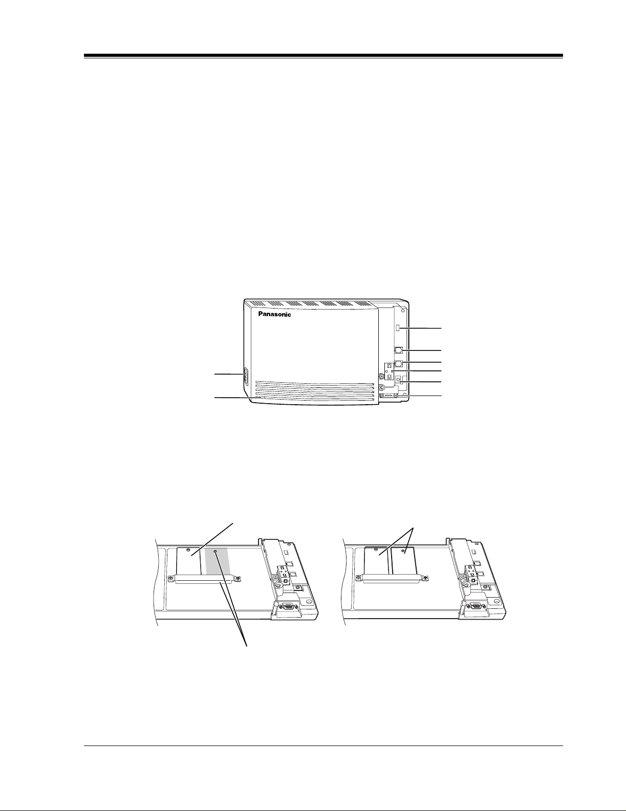
1.3.2 System Components
Main Cabinet
1.3 SYSTEM BASICS
MODE (DIP Switch)
AC Inlet
Power Indicator
POWER
VOICE PROCESSING SYSTEM
Inside View of the Main Cabinet
KX-TVS50 KX-TVS80
Memory Card
Memory Card
Master
Port 1
Port 2
Ferrite Core
Ground Terminal
EIA (RS-232C)
Connector
Slave
Position for Optional Expansion Memory Card
VOICE PROCESSING SYSTEM OVERVIEW
17
Page 18
1.3 SYSTEM BASICS
System Components
AC Inlet:
Connects the power cable to an AC outlet dedicated for the VPS.
Power Indicator:
Indicates s ystem status — when flashing, the system is off-line (not ready to receive calls).
MODE (DIP Switch):
(Check the status of this switch only at start-up.) Provides the following additional functions:
0 Normal setting. (All switches in 0 position.)
1
2
Table 1
Position Additional Function
01
•1
01
•2
01
•3
01
•4
01
•1
Initializes RS-232C parameters.
01
•2
01
•3
01
•4
RS-232C default parameters: 9,600, N, 8, 1
01
•1
Auto Configuration is automatically executed and
01
*1
•2
01
•3
01
all ports are set for Automated Attendant service.
•4
01
•1
Auto Configuration is automatically executed and
01
3
*1
•2
01
•3
01
all ports are set for Voice Mail service.
•4
4 Reserved.
01
•1
Initializes the VPS. Clears all voice data and
01
5
•2
01
•3
01
returns all system parameters to the default setting.
•4
6-9 Reserved.
01
•1
Auto Configuration is automatically executed and
01
10
11
*2
*2
•2
01
•3
01
all ports are set for Automated Attendant service.
•4
01
•1
Auto Configuration is automatically executed and
01
•2
01
•3
01
all ports are set for Voice Mail service.
•4
12-15 Reserved.
*1
For Panasonic KX-TD series telephone systems with DPT
Integration
*2
For Panasonic KX-TA624 telephone system with APT
Integration.
To change the position, use a pointed object, such as a pen, etc.
18
VOICE PROCESSING SYSTEM OVERVIEW
Page 19

1.3 SYSTEM BASICS
Note
When setting the DIP switc h to any position (except 0), first disconnect the st ation wire(s)
and wait a few minutes, then disconnect the AC cord from the VPS. Set the DIP switch
and connect the A C cord t o the VPS, wait appro ximately 3.5 min and then retur n the DIP
switch to position 0.
Ground Terminal:
This terminal should be connected to a ground source with less than 1 resistance.
EIA (RS-232C) Connector:
Connects an ASCII or VT terminal to the VPS; must be used to program system.
Memory Card:
(1/system) Stores the pr oprietary system program, and the voice prompts (about 30 min worth);
has the capacity to record approximately 2 h (KX-TVS50) or 6h (KX-TVS80) of messages
from callers.
Optional Expansion Memory Card:
The KX-TVS52 can expand the flash memory capacity of the KX-TVS50 by 2 h.
1.3.3 Which Phone Systems are Compatible?
We recommend integration with the following Panasonic phone systems:
•
Panasonic KX-TD1232
•
Panasonic KX-TD816
•
Panasonic KX-T336
•
Panasonic KX-T123211D, KX-TA624
•
Panasonic KX-TD308
We cannot guarantee adequa te i ntegration of the KX-TVS50/80 with other PBX sys te ms or
with Key Systems. If the customer does not have one of the recommended Panasonic PBX
systems, be sure that the system has the features listed below.
The PBX should have the following features for successful integration:
•
Single line (tip/ring) port circuits (Some PBXs need an OPX card to provide this
connection.)
•
Station to station DTMF signaling
•
Message Waiting Notification from an SLT (single-line telephone)
•
Screened transfer from an SLT
•
Message Waiting Notification on proprietary (multi-line) sets (message waiting lamp
accessed by dialing on/off codes)
If the PBX does not have these features, VPS operation will be limited.
VOICE PROCESSING SYSTEM OVERVIEW
19
Page 20

1.3 SYSTEM BASICS
See 3.1.4 PBX Requirements for Integration. You will find the fol lo wing infor mation about
each feature listed:
VOICE MAIL
The recommended Panaso nic PBX syst ems have Follo w-on ID an d Inband I nte gr atio n. When
callers are transferred to an extension that is forwarded to Voice Mail, Follow-on ID sends
callers directly to the mailbox. Without Follow-on ID, the caller would have to re-enter the
mailbox number when connected to the Voice Mail.
DTMF Integration enables the VPS to recognize the current state of the call and improve its
call handling performance. When enabled, the PBX informs the VPS of the status of the call
(busy, answered, ringing, etc.) by sending a code wit h DTMF tones befor e sending t he normal
call progress tones. For example, when a caller hangs up before making a selection, the PBX
sends # 9 to the VPS port that answered. This informs the VPS that the caller has hung up.
Upon receiving these digits, the VPS goes on-hook and is ready to handle another call.
•
Description
•
Limitations of the system without the feature
•
Tests to determine whether the PBX has the feature
Digital (APT/DPT) Integration is available when the VPS is connected to a Panasonic KXTA624 or to a Panasonic KX-TD series PBX (d epending on the softw are v ersion ). This dig ital
integratio n provides the VPS with more informat ion than DTMF Integr ation. This infor mation
enables the system to identify the extension number of the caller, know where the call is
forwarded from and why, and recognize what the caller wants to do. Some features are
available only with APT/DPT Integration (Live Call Screening, Two-Way Recording, TwoWay Transfer, Direct Mailbox Access, Intercom Paging, Auto Configuration, Caller Name
Announcement (system/personal), Caller ID Call Routing, Personal Greeting for Caller ID).
1.3.4 Installer Equipment and Software Requirements
The installer
software. We suggest you use something like HyperT e rminal by HILGRAEVE. The computer
is used to progra m the VPS. Terminal emulation software enables the ke yboar d to be use d as a
data entry device.
While both the laptop and data terminal will work, the laptop allows screens to be saved in a
file thr oughout the pr ocess. It is of ten hel pfu l to retr ie ve these files late r i f tec hnical suppor t is
needed.
have a l apt op c omput er or data terminal equipped with terminal emulation
must
20
VOICE PROCESSING SYSTEM OVERVIEW
Page 21

1.3.5 Specifications
Number of Messages per Mailbox: 100 maximum (programmable)
1.3 SYSTEM BASICS
Table 2
Ports: 2
Voice Storage: KX-TVS50: 2h (expandable)
KX-TVS80: 6h (non-expandable)
Custom Services: 100
Message Retention: 1 to 30 days or unlimited
Number of Mailboxes: KX-TVS50: 30 subscriber mailboxes
2 manager mailboxes
KX-TVS80: 62 subscriber mailboxes
2 manager mailboxes
1.3.6 Hardware
•
1 (KX-TVS50) or 2 (KX-TVS80) Flash Memory Card(s).
•
1 Optional Flash Memory Position for KX-TVS52 card
•
2 Telephone Inputs (RJ11C)
•
1 RS-232C Connector
•
1 DIP Switch (4-bit)
1.3.7 Flash Memory Expansion Capabilities
*1
*1
Expansion of the flash memory capacity requires an optional expansion memory card (KXTVS52). The KX-TVS50 initially has 2- h memory. The KX-TVS52 increases the capacity by
2 h.
1.3.8 Recommendations for System Configuration
General guideline: a ratio of 6/1 (for every 6 lines, 1 port). There are 2 questions to ask when
considering how many ports are desirable:
• Are the ports answering all incoming calls or just forwarded/transferred calls?
• If they are answering incoming calls, how busy are the lines?
The guideline above (6/1) usually works well with moderate traffic. This may have to be
modified for heavy traffic. These recommendations are outlined in the following chart.
*1
Available for the KX-TVS50 only.
VOICE PROCESSING SYSTEM OVERVIEW
21
Page 22

1.3 SYSTEM BASICS
One port may not support an Automated Attendant configuration with 5 CO lines. The
following recommendations for Automate d Attendant ports may ha ve to be modified fo r heavy
traff ic.
Table 3
CO Lines Port
1-6 1
7-12 2
Table 4
CO Lines Port
1-4 1
5-8 2
22
VOICE PROCESSING SYSTEM OVERVIEW
Page 23
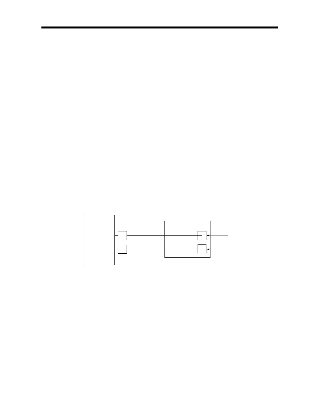
1.4 DIGITAL INTEGRATION
KX-TVS50/80
Port 1
Extension 107
7
8
KX-TA624
Port 2
Extension 108
1.4.1 General
There are 2 types of Digital Integration: APT Integration and DPT Integration.
APT Integration is available when the KX-TVS50/80 is connected to a KX-TA624. DPT
Integration is available when the KX-TVS50/80 is connected to a KX-TD digital PBX.
1.4.2 APT Integration
To the Panason ic KX-TA624, the VPS ports loo k lik e propri etar y tel ephones . The PBX think s
that the VPS is a proprietary telephone, and the VPS mimics all actions of a proprietary
telephone. Communication bet ween the VPS and the PBX thr ough digit al inte gration r equires
the proper software l eve l in the PBX and 4-wire conn ections for each po rt (KX-TVS50/80). To
communicate between the VPS and the PBX through APT Inte gration, the PBX and VPS must
be programmed to work together.
1.4 DIGITAL INTEGRATION
1.4.3 Connection Example — APT Integration
For example, you can connect jack 7 of the KX-TA624 to Port 1 of the VPS with a 4-wire
connection (see diagram belo w). Thi s connectio n creates 1 Voice Mail extension and can only
answer 1 call. This mea ns tha t a fully- conf igured 2-port s ystem requ ires 2 jac ks from th e PBX.
When APT Integration is act iv ated, a si ngle exte nsion jack prov ides 1 single-l ine interf ace at a
Port on the VPS. For exa mple , when 1 l ine cor d (4 wi re ) is connected to Port 1 on the VPS, 1
extension is provided.
1.4.4 DPT Integration
To the Panasonic KX-TD digital PBX, the VPS ports look like digital extensions. The PBX
thinks that the VPS is a digital phone, and the VPS mimi cs all acti ons of a digi tal s et. Anot her
advantage of digit al integration is that the 2B+D communication pro vides 2 VPS ports for each
Digital Station port . Communication between the VPS and the PBX through di gital integ ration
requires the proper software level in the PBX and 4-wire connections for each port (KX-
VOICE PROCESSING SYSTEM OVERVIEW
23
Page 24
1.4 DIGITAL INTEGRATION
TVS50/80). T o communicate be tween the VPS and the PBX through DPT Inte gration, the PBX
and VPS must be programmed to work together.
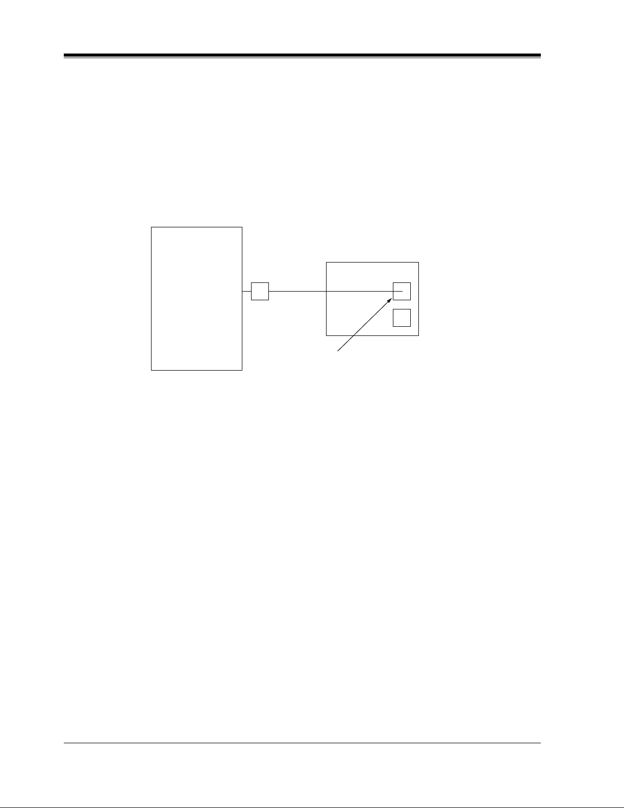
1.4.5 Connection Example — DPT Integration
For example, you can connect jack 15 of the KX-TD1232 to Port 1 of the VPS with a 4-wire
connection (see diagram below). This connection creates 2 Voice Mail extensions and can
simultaneously answer 2 ca lls. This means t hat a full y-configured 2-port syst em req uires only
1 jack from the PBX.
KX-TVS50/80
KX-TD1232
15
Port 1
Extensions 165 and 166
When DPT Integration is activated, a sin gle e xte nsion j ack pro v ides 2 singl e-lin e inte rf aces at
a Port on the VPS. For example, when 1 line cord (4 wire) is connected to Po rt 1 on the VPS,
2 extensions are provided.
24
VOICE PROCESSING SYSTEM OVERVIEW
Page 25

Section 2
INSTALLATION
INSTALLATION
25
Page 26

2.1 SAFETY PRECAUTIONS
2.1 SAFETY PRECAUT IONS
Please read the following precautions before installing the VPS.
2.1.1 Installation
The VPS needs to be installed on the wall. Improper placement of the system may result in
malfunction, noise, or discoloration. Avoid installing the VPS in the following places:
•
in direct sunlight; in hot, cold, or humid places
•
in new areas where there are t her mal s pri ngs , etc . (whe re sulfuric gas may damage the
equipment or contacts).
•
where shocks or vibrations are frequent or strong.
•
in dusty places or places where water or oil may come in contact with the unit.
•
near high frequency generating devices such as sewing machines, elevators or electric
welders.
•
on or near computers, telexes, or other office equipment; near microwave ovens or air
conditioners. (Idea lly , the VPS sho uld not be in the r oom wit h these items and shoul d be
at least
1.8m {6 feet}
away from televisions.)
Do not obstruct the areas aro und the PBX and the VPS.
and space on the sides for maintenance and inspection.
2.1.2 Wiring
•
Do not wir e the telepho ne cable par allel to an A C power sou rce , computer, etc. If cables are
run near those wir es, shield the c ables with meta l tubing or u se shielded cables and ground
the shields.
•
Use protectors if running cables on the floor. Avoid running wire under carpets.
•
A void sharing a 120
with the VPS. Induction noise from such equipment may interrupt the VPS operation.
When making any connections or remo ving the co ver, be sure the power switc h is turned of f.
When installing telephone wiring, basic safety precautions should always be followed to
reduce the risk of fire, electric shock and injury to persons, including the following:
• Never install telephone wiring during a lightning storm.
• Nev er install telepho ne jacks in wet locations unles s the jack is specif ically designed for
wet locations.
• Nev er touch u ninsulated tel ephone wires or terminal s unless the telephone l ine has been
disconnected at the network interface.
• Use caution when installing or modifying telephone lines.
Both require space abo ve for cool ing
V AC
power supply for computer s, tele xes, and other of f ice equipment
26
INSTALLATION
Page 27

2.2 UNPACKING
Unpack the box and check the items below.
Table 5
Main Unit 1
AC Cord 1
Screws (Wall Mounting) 3
Washers (Wall Mounting) 3
2.2 UNPACKING
INSTALLATION
27
Page 28
2.3 MOUNTING THE VPS ON A WOODEN WALL
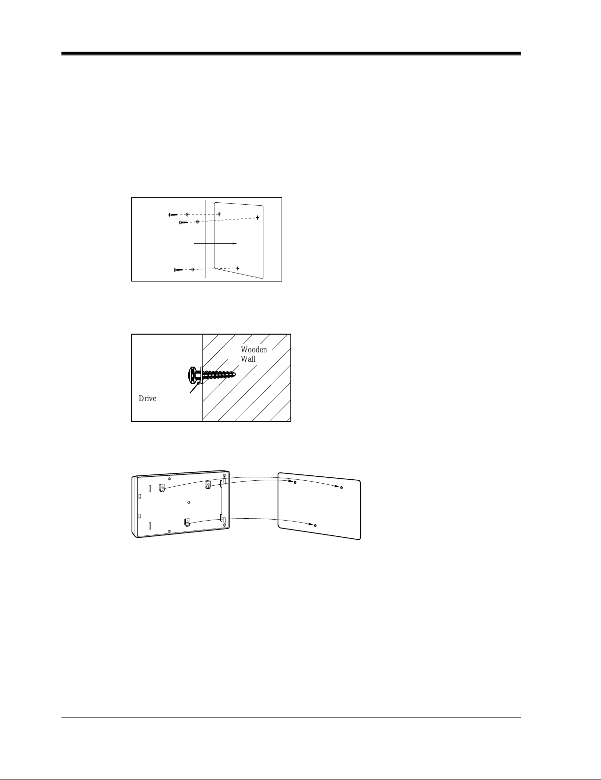
2.3 MOUNTING THE VPS ON A WOODEN WALL
The wall where the VPS is to be mounted must be able to support the weight of the VPS. If
screws other than the ones supplied are used, use the same-sized diameter screws as the
enclosed ones.
Place the template included on the wall to mark the 3 screw positions.
1.
Template
Install the 3 screws (included accessories) into the wall.
2.
Wooden
Wall
Drive the screw
to this position.
Hook the unit on the screw heads.
3.
,
28
INSTALLATION
Page 29
2.4 FRAME GROUND CONNECTION
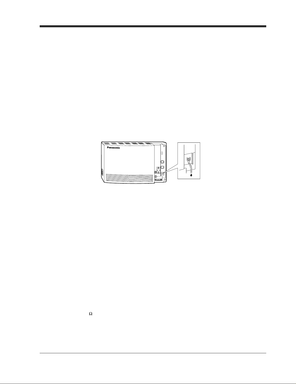
2.4 FRAME GROUND CONNECTION
IMPORTANT!!!
Connect the frame of the main unit to the ground.
Loosen the screw.
1.
Insert the grounding wire.
2.
Tighten the screw.
3.
Connect the grounding wire to the ground.
4.
In most of North America , the g round pr o vid ed by th e "Thi rd wire ground" at t he commerc ial
or residential power outlet will be satisfactory. However, in some cases this ground may be
installed incorrectly. Therefore, the following test procedure should be performed.
Test Procedure
Obtain a suitable voltmeter and set it for a possible reading of up to 250 V AC.
1.
Connect the meter probes between the 2 main AC voltage points on the wall outlet. The
2.
reading obtained should be 108 V AC-132 V AC.
Move one of the meter probes to the third prong terminal (GND).
3.
Either the same reading or a reading of 0 V should be obtained.
If a reading of 0 V at 1 terminal and a readi ng of 108 V A C- 132 V A C at the other termi nal
4.
is not obtained, the outlet is not properly grounded. This condition should be corrected by
a qualified electrician (per article 250 of the National Electrical Code).
If a reading of 0 V at 1 terminal and a readi ng of 108 V A C- 132 V A C at the other termi nal
5.
is obtained, then set the meter to the "OHMS/RX1" scale, place 1 probe at the GND
T er mina l and the oth er pro be at the te rminal which g a v e a read ing of 0 V. A reading of less
than 1 should be obtained. If the reading is not obtained, the outlet is not adequately
grounded. See a qualified electrician.
VOICE PROCESSING SYSTEM
POWER
To ground
INSTALLATION
29
Page 30

2.5 INSTALLATION STEPS
2.5 INSTALLATION STEPS
The followi ng is an o v er vie w of the st andard insta llat ion pro cess usi ng APT/DPT In te grat ion.
When necessary, other sections in this manual have been referenced for more detailed
descriptions or instructions.
Get a list of current users, their extension numbers, their departments, and the type of
1.
systems they use (mailbox, no mailbox, beeper, car phone...).
Assess your customers' needs bef ore setting up the system. You will sav e yourself time later
2.
by giving customers what the y nee d up front. Ask the of f i ce manager ho w the VPS will be
used. Give examples.
Recommend that your customer use a word processor to log the greetings. You will find
these files much more easily than the worksheet pages if you need to make changes down
the road.
Standard Initialization (For APT/DPT Integration Connection)
3.
Program the ports of the PBX for voice processings (See Section 4 INTEGRATING
a)
THE VPS WITH THE PANASONIC KX-TA ANALOG PBX AND KX-TD DIGITAL
PBX).
Program the KX-TA624, the KX-TD1232, the KX-TD816 or the KX-TD308 for
Voice Mail integration.
•KX-TA624
• KX-TD816, KX-TD1232, KX-TD308
Program may be performed on-site or at the office.
All memory is stored and will be retained when the unit is powered up as long as
the DIP switch has been reset to position [0] prior to turning the unit off.
Unplug the power cord of the VPS.
b)
Plug station wire(s) from the PBX into VPS (See 2.7 CONNECTIONS).
c)
Connect the computer to the VPS with a Null Modem Cable (See 2.8.2 Connecting the
d)
RS-232C Cable).
Set the DIP switch to position 5.
e)
Plug the power cord of the VPS.
f)
Wait until the "warning" appears on the screen.
g)
Set the DIP switch back to position 0.
h)
CAUTION
If the DIP switc h is not rese t to positio n 0 after initi alization, all programming wil l be lost
when the voice processor loses power!
30
INSTALLATION
Page 31

2.5 INSTALLATION STEPS
Perform Quick Setup. (See Section 5 CUSTOMIZING THE SYSTEM)
4.
Check Quick Setup:
5.
• The Power Indicator on the Voice Processor should be solid.
• The screen output should be: [On Line].
If you do not see the "On Line" message, check the following:
• The line cord to the Voice Processor has 4 conductors.
• The programming on the KX-TA624 is correctly set in system Program [130], or
[130] and [131].
• The programming on the KX-TD816/1232/308 is correctly set in System Program
[117].
Set up Class of Service (COS) for each user. Customize voice prompts if necessary. (See
6.
Appendix B SYSTEM ADMINISTRATOR'S GUIDE)
Perform Administrative Program through a computer. (See Appendix B SYSTEM
7.
ADMINISTRATOR'S GUIDE)
CAUTION
Do not turn the power off while the VPS is activated so as not to cause malfunction.
To turn the power off after installing the VPS, unplug the power cord from the VPS a
few minutes after disconnecting station wire(s).
INSTALLATION
31
Page 32

2.6 INSTALLING AN OPTIONAL EXPANSION MEMO RY CARD (KX -TVS52)
2.6 INSTALLING AN OPTIONAL EXPANSION
MEMORY CARD (KX-TVS52)
2.6.1 General
The flash memory capacity of the KX-TVS50 can be increased from 2 h to 4 h if an optional
expansion memory card (KX-TVS52) is installed.
2.6.2 Installing the KX-TVS52
Disconnect the station wire(s). Wait a few minutes then disconnect the AC cord from the
1.
VPS.
Take out the screw.
2.
Screw
*1
VOICE PROCESSING SYSTEM
POWER
Remove the cover by pressing both tabs and lifting up.
3.
VOICE PROCESSING SYSTEM
POWER
Take out the screws and remove the metal bar.
4.
Screws
*1
Available for the KX-TVS50 only.
32
Metal Bar
INSTALLATION
Page 33

2.6 INSTALLING AN OPTIONAL EXPANSION MEMORY CARD (KX-TVS52)
Attach the optional expansion memory card firmly. Secure the screw.
5.
Screw
SLAVE
CAUTION
Do not attach the op ti onal expansion memory car d a t the "MASTER" po siti on. Atta c h it at t he
"SLAVE" position.
Replace the metal bar and secure the screws.
6.
Screws
Replace the cover and secure the screw.
7.
Connect the AC cord again.
8.
INSTALLATION
33
Page 34

2.7 CONNECTIONS
2.7 CONNECTIONS
2.7.1 Connecting to the PBX
The KX-TVS50/80 can be connected to up to 2 e xtension port s of the PBX. Use a 4-conductor
wire for connection with KX-TA624 that uses APT Integration, and for connection with KXTD systems that use DPT Inte gration. Use a 2-condu ctor wire for connecti on to all other PBXs.
4-Conductor Wire
Y
G
R
B
Modular Connection
B: BLACK
R: RED
G: GREEN
Y: YELLOW
2.7.2 Opening the Ferrite Core
Insert your finger into the opening of the ferrite core and open it as shown below.
Outer Pins
Inner Pins
Y
G
R
B
34
Connect a 4-conductor wi re or 2-conductor wir e to the KX-TVS50/80 and run the wire through
the ferrite core (see following p ages). Close the ferrite core.
INSTALLATION
Page 35

2.7.3 Connection for APT Integration
Y
G
R
B
Y
G
R
B
To KX-TD1232/816/308
To Extension
Port of the PBX
PORT 1
PORT 2
PORT 1
Telephone Line
Modular Jacks
PORT 2
Any Extension Jack except Jack 01
Ports 1-2 of the KX-TVS50/80
Telephone Line
Modular Jacks
PORT 1
2.7 CONNECTIONS
PORT 1
PORT 2
PORT 2
Extension Jacks 07 and 08
To Extension
Port of the PBX
Y
G
R
B
(or 15 and 16)
2.7.4 Connection for DPT Integration
Ports 1-2 of the KX-TVS50/80
To KX-TA624
Y
G
R
B
INSTALLATION
35
Page 36

2.7 CONNECTIONS
2.7.5 Connection for Non-APT/DPT Integration
Ports 1-2 of the KX-TVS50/80
Telephone Line
Modular Jacks
PORT 1
PORT 1
PORT 2
To Extension
Port of the PBX
PORT 2
To Extension Ports of
Non-APT/DPT Integration PBX
G
R
G
R
36
INSTALLATION
Page 37

2.8 TERMINAL CONNECTION
2.8 TERMINAL CONNECTION
2.8.1 Requirements for Connecting Programming Terminal
The programming terminal must be co nnecte d with a ser ial ca ble wit h an RS-2 32C connect or
at the EIA port. This must be a null modem cabl e. This ena bles syst em administ ration ( system
setup, mailbox setup, and system diagnosis) to be performed.
Communication parameters of the VPS have been set to the following values at the factory:
Table 6
COMMUNICATION PARAMETERS
Baud Rate: 9600 bps
Word Bit Length: 8 Bits
Parity: None
Stop Bit Length: 1 Bit
2.8.2 Connecting the RS-232C Cable
STOP:
Before connecting the cable, make sure the power switches on both the data terminal and
the VPS are OFF.
VOICE PROCESSING SYSTEM
POWER
Insert the RS-232C cable into the VPS with the connector indicating the same direction.
INSTALLATION
The cable must be shielded and no longer than 2m {6.5 feet}.
37
Page 38

2.8 TERMINAL CON NECTION
KX-TVS50 (9 pin)
Circuit
(EIA)
type
BB
BA
CD
AB
CC
Signal
name
RXD
TXD
DTR
SG
DSR
Pin
no.
KX-TVS50 (9 pin)
Circuit
(EIA)
type
Signal
name
Pin
no.
9-pin Cable Printer/IBM-PC
name
RXD
TXD
DTR
SG
DSR
RTS
CTS
Circuit
type
(EIA)
BB
BA
CD
AB
CC
CA
CB
Signal
Pin
no.
2
3
4
5
6
2
3
4
5
6
7
8
25-pin Cable Printer/PC
name
Circuit
type
(EIA)
Pin
no.
Signal
BB
BA
CD
AB
CC
Pin
Number
1
2
3
4
RXD
TXD
DTR
SG
DSR
2
3
4
5
6
1
3FGRXDAABB
2
TXD BA
20
DTR
7
SG
5
CTS
6
DSR
8
DCD
CD
AB
CB
CC
CF
Table 7 Pin Configuration of the EIA (RS-232C)
Signal Name
FG
TXD
RXD
RTS
Frame Ground
Transmitted Data
Received Data
Request To Send
Circuit Type
EIA CCITT
AA
BA
BB
CA
101
103
104
105
38
6 DSR Data Set Ready CC 107
INSTALLATION
Page 39

Table 7 Pin Configuration of the EIA (RS-232C)
2.8 TERMINAL CONNECTION
Pin
Number
7
8
20 DTR Data Terminal Ready CD 108.2
SG
DCD
Signal Name
Signal Ground
Data Carrie r Detect
2.8.3 EIA (RS-232C) Signals
Frame Ground (FG)
Connects an external ground to the unit frame, usually the ground pin of the AC power cord.
Transmitted Data (TXD)—output
Conv eys si gnals from t he unit to t he terminal /printer. A "mark" condition is held unless data or
BREAK signals are being transmitted.
Received Data (RXD)—input
Conveys signals from the terminal/printer to the unit.
Circuit Type
EIA CCITT
AB
CF
102
109
Request To Send (RTS)—output
This lead is held on whenever DSR is on.
Signal Ground (SG)
Connects to the DC ground of the unit for all interface signals.
Data Terminal Ready (DTR)—output
This signal line is turned on by the unit to indicate that it is on line. Circuit DTR ON does not
indicate that communication has been established with the terminal/printer. It is switched off
when the unit is off-line.
INSTALLATION
39
Page 40

2.8 TERMINAL CON NECTION
40
INSTALLATION
Page 41

Section 3
INTEGRATING THE VPS WITH
PANASONIC KX-T PHONE SYSTEMS
INTEGRATING THE VPS WITH PANASONIC KX-T PHONE SYSTEMS
41
Page 42

3.1 GUIDELINES FOR INTEGRATION
3.1 GUIDELINES FOR INTEGRATION
3.1.1 APT/DPT or Inband Signaling?
There are 3 types of integration available on the KX-TVS50/80: Inband Signaling, APT and
DPT. The VPS used with any other brand of telephone equipment require inband equipment.
KX-TA624 that can use APT Integration is:
• KX-TA624 Version Y581A or higher
KX-TD seri es PBXs that can use DPT Integration are:
• KX-TD308 Version P871F or higher
• KX-TD816 Version P301O or higher
• KX-TD1232 Version P231U or higher
3.1.2 Why Integration is Important
The KX-TVS50/80 works well with most PBXs because its connections are made through a
standard single-l ine (tip/ ring) telephon e interfac e. Howe v er , the VPS operation depends on t he
capabilities and featur es provide d by the PBX; its performanc e will va ry when connected with
different PBX systems. For example, Follow-on (or Called Party) ID is a feature of the PBX.
If the PBX does not have this feature, the VPS cannot transfer calls directly to the correct
mailbox and play the busy or no-answer greeting for that mailbox.
3.1.3 How the VPS and the PBX Communicate
T o the PBX, the VPS looks like SLT sets. The PBX thinks that the VPS is an SLT, and the VPS
mimics all actions a live attendant would carry out from an SLT.
For the VPS and the PBX to communicate, proper signaling is important. Like an attendant,
the VPS places calls by going off-hook and dialing numbers. It starts call transfers with a
hookswitch flash to put callers on hold and then dials the extension number. By recognizing
call progress tones from the PBX, the VPS decides how calls should be handled. Inband
Integration allows the PBX to send certain digits (DTMF) to the VPS, allowing it to recognize
the status of the extension and take the appropriate action.
Table 8
VPS/PB X COMMUNICATION
PBX to VPS
Call Progress Tones SLT Signals
• ringback
•busy
• reorder
VPS to PBX
• on/off hook
• hookswitch flash
• DTMF tones
42
INTEGRATING THE VPS WITH PANASONIC KX-T PHONE SYSTEMS
Page 43

Table 8
VPS/PBX COMMUNICATION
DTMF Tones
The VPS must also have access to certain PBX features. For example, if the VPS takes a
message, one way it can notify the mailbox owner is by dialing the PBX's Message-WaitingLamp-On code. Once new messages are retrieved, the VPS dials the Message-Waiting-LampOff code for that same mailbox owner.
3.1.4 PBX Requirements for Integration
The PBX must have certain capabilities and features to work with the VPS. (Although this
section includes tests to help you evaluate the PBX, it may be necessary to refer to the PBX's
documentation for detailed capability and feature descriptions.)
Single Line (Tip/Ring) Port Circuits
The VPS can only be connected to a PBX that supports SLT sets. Some PBXs need an OPX
card to provide th is connecti on.
listed in this section.
Howev er, some OPX cards do not provide all the capabi lities
3.1 GUIDELINES FOR INTEGRATION
Following are the minimum current and voltages that the PBX must supply:
Table 9
Minimum Loop Current 20 mA
Minimum Line Voltage 7 V DC
Minimum Ringing Voltage 40 V AC
Station to Station DTMF Signaling
For system users to access VPS services and features, they must be able to send DTMF tones
from their telephones to the VPS port. As a general rule, SLT sets can perform station-tostation DTMF signaling; however, many proprietary telephones cannot. Some PBXs need to
be programmed to m ake proprietary sets use DTMF signaling.
If the PBX does not provide station-to-station DTMF signaling, VPS services and features
will be limited.
TEST:Call an SLT extension from the tel epho ne in ques tion. When the cal l
is answered, see if the person receiving the call hears DTMF tones when
numbers are dialed.
INTEGRATING THE VPS WITH PANASONIC KX-T PHONE SYSTEMS
43
Page 44

3.1 GUIDELINES FOR INTEGRATION
Message Waiting Notification from an SLT
The PBX extensi ons should light a lamp or rec eiv e stutter di al tone when the Message-WaitingLamp-On code is dialed by the VPS. The VPS functions best when the extension number of
the voice mailbox o wner follo ws the Light-On or Light -Off code. On some PBXs, howev er , the
extension number is dialed first, followed by a hookswitch flash and then the On code. This
presents a problem if the extension is answered before the VPS sends the hook-switch flash.
If the PBX does not provide message waiting notification from an SLT, the VPS can only
notify mailbox owners by dialing a beeper number or user-assigned extension.
This process slo ws do wn VPS performance as it dials the bee per or exte nsion number and wa its
to confirm notif ica tion. The beepe r or user -ass igned e xtension no tif icati on is meant to be us ed
for necessity, usually for mailbox owners who are often out of the office (e.g., salespeople or
field representatives). The only other option, without message waiting notification, is for
mailbox owners to periodically call the VPS to check for messages.
TEST: See if dialing the On code from an SLT can turn on an extension's
message waiting indicator.
Screened Transfer from an SLT
The PBX must provide a screened transfer from an SLT for the VPS to function properly.
A screened transfer:
1. Puts the caller on hold, usually with a hookswitch flash.
2. Dials the extension.
3. Checks to see if the calle d subsc riber is in, o ut, or on anot her li ne , and wh ether or not t hat
subscriber accepts the transfer.
4. Completes the transfer (by going on-hook) or returns to the caller to say that the party is
busy or not available. It then gives the caller an opportunity to leave a message.
If the PBX does not provide screened transfer from an SLT, the VPS cannot give callers the
option to leave a message in a subscriber's mailbox.
TEST: Place an outside call from an SLT. See if you can set up a screened
transfer to a nother exten sion. Next, try the same test with an internal cal l.
(The VPS may have to tr ansfer both types of calls.)
Follow-on ID or Called Party ID
When forwarding or transf erring a call to the VPS, a PBX with Follo w-on ID sends the mailbox
number of the call ed subscr iber to the VPS befo re connect ing the caller. The VPS responds by
playing that subscriber 's personal greeting . This operation is someti mes called Call For ward to
44
INTEGRATING THE VPS WITH PANASONIC KX-T PHONE SYSTEMS
Page 45

3.1 GUIDELINES FOR INTEGRATION
Mailbox. W i t hout t h is fe at ure , t he VPS cannot immediately play the greet i ng whe n the line is
busy or there i s no answer and allow the caller to leave a message.
INTEGRATING THE VPS WITH PANASONIC KX-T PHONE SYSTEMS
45
Page 46

3.2 PBX PARAMETERS AND PORT SETTINGS
3.2 PBX PARAMETERS AND PORT SETTINGS
3.2.1 General Guidelines and Definitions
Optimal performance of the VPS/PBX system relies on proper VPS programming. There are
3 categories of hardware settings: RS-232C, Port Settings, and PBX Interface Parameters.
Entering a number sets some of the parameters, while others use sequence codes.
3.2.2 RS-232C Settings
Baud Rate (300 - 38400):
•
transferred).
Word Bit Length (7 - 8):
•
Parity (N, O, E):
•
Stop Bit Length (1 - 2):
•
Default:
•
9600, 8, N, 1
Specifies the parity used for error detection.
Specifies the bits-per-second (the speed at which the data is
Defines the number of bits in each byte or character.
Specifies the number of bits used to signify the end of the byte.
3.2.3 Port Settings
There is no need to change these in a typical insta llation.
using a CO (central of f ice) li ne directly to the KX-TVS50/80. Ea ch port on t he VPS should be
matched to the type of signaling the PBX expects. If you need to change these settings, refer
to the PBX manual or customer support office to get the correct values for these settings.
Flash Time—100, 300, 600, 900
•
The minimum amount of time that the PBX requires to recognize a hookswitch flash.
Choose the amount that is equal to or greater than the PBX's setting.
CPC Signal (Calling Party Control Signal)—NONE, 6.5, 150, 300, 450, 600
•
The amount of time allowed for the short break in loop current that is used to indicate
that the caller has hung up; usually set to NONE, since most PBXs do not provide this
signal to single line port s. If c ho osing a set ting other than NONE, use an amount e qual
to or less than the PBX or telephone company provided CPC signal.
Disconnect Time—1 - 8
•
The amount of time that the line is temporarily unavailable after a call has ended.
Dial Mode—DTMF, Pulse 10
•
The type of signaling the PBX single line port expects to receive. (
second)
s:
ms:
, Pulse 20
pps
Only change these parame ters when
ms:
:
pps
pps
= pulses per
46
INTEGRATING THE VPS WITH PANASONIC KX-T PHONE SYSTEMS
Page 47

3.2.4 PBX Interface Parameters
Dialing Parameters
PBX Type:
•
Specifies the type of PBX which is connected to the VPS.
Integration Mode:
•
Specifies the method of inte gr ation to be use d between the VPS and PBX. If PBX ty pe is set
to the Panasonic KX-T series, the Inband Signaling parameters are set automatically and
should not be altered. APT Integration is only available when a KX-TA624 PBX is
connected and the software is upgraded. DPT Inte gr a tion is only availab le when a KX-TD
series PBX is connected and the software is upgraded.
Table 10
SEQUENCE CODES
D Disconnect
F Hookswitch Flash
3.2 PBX PARAMETERS AND PORT SETTINGS
R Ring Detection
S Silence Detection
T Dialtone Detection
W Wait for 1 Second
X Dial Extension
A: Answer
0-9, , #
Operator Transfer Sequence:
•
Tells the VPS how to transfer a call to the operator.
Example:
Extension Transfer Sequence:
•
Tells the VPS how to transfer a call to an extension.
Example:
Alternate Extension (Transfer Sequence):
•
Tells the VPS how to transfer a call to an extension t hat is entered into the "Alternate
Extension Gr oup." Thi s is useful for e xten sions that ne ed a special tr ansf er procedur e (i.e .,
blind transfer) such as modem extensions.
Example:
Reconnect Sequence on Busy:
•
Tells the VPS how to return to the caller if the ext ension the caller has dialed is b usy . PBXs
differ in how they handle this function. Test from an SLT to determine the sequence.
Reconnect Sequence on No Answer:
•
Tells the VPS how to return to the caller if the extension the caller has dialed does not
FTX [hookswitch flash—dial tone—dial (operator) extn.]
FTX [hookswitch flash—dial tone—dial extn.]
FTXD [hookswitch flash—dial tone—dial extn.—hang up]
DTMF Digits
INTEGRATING THE VPS WITH PANASONIC KX-T PHONE SYSTEMS
47
Page 48

3.2 PBX PARAMETERS AND PORT SETTINGS
answer. PBXs differ in how they handle this function. Test from an SLT to determine the
sequence.
Reconnect Sequence on Refused Call:
•
Tells the VPS how to return to the caller if the e xtension dialed has Call Scr een ing enabled
and the subscriber ch ooses not to take the c all. PBXs differ in how th ey handle thi s function.
Test from an SLT to determine the sequence.
Light On Sequence for Message Waiting Lamp:
•
This is the dialing sequenc e that the VPS must us e to turn on a messa ge waiting lamp at an
extension.
Light Off Sequence for Message Waiting Lamp:
•
This is the dialing sequ ence that the VP S must use to turn off a mes sage wait ing lamp at an
extension.
Call Waiting S equence:
•
This sequence is carried out by the VPS to perform call waiting when the extension being
called is busy. PBXs differ in how the y ha ndl e this function. Test from an SLT to determine
the sequence.
Release Sequence for Call Waiting:
•
This sequence is carried out by the VPS to release call waiting. PBXs differ in how they
handle this function. Test from an SLT to determine the sequence.
Inband Signaling
These parame ters are used when the Integrat ion Mode is set to Inband. If the PBX type is set
to a KX-T series system, these parameters will be automatically set. If another type PBX is
used, check that system's installation manual for settings.
Code
(default)
1 Ringback Tone The extension dialed is ringing.
2 Busy Tone The extension dialed is busy.
3
4 DND The extension dialed has set DND feature (Do Not Dist urb).
5 Answer The extension dialed is answered.
6
Table 11
Call State Sent to the Voice Mail Port When...
Reorder Tone An invalid extension number is dialed or the call is
inadvertently connected to another Voice Mail port (also
heard when no DTMF recei ver is a vaila ble to the Voice Mail
extension).
Forwarded to V oice
Mail (Ringing)
The extension dialed is forwarded to Voice Mail and another
Voice Mail port is able to answer. (This lets the first Voice
Mail port, usually an Auto Attendant, send the call to the
other Voice Mail port.)
48
INTEGRATING THE VPS WITH PANASONIC KX-T PHONE SYSTEMS
Page 49

Table 11
3.2 PBX PARAMETERS AND PORT SETTINGS
Code
Call State Sent to the Voice Ma il Port When...
(default)
Forward ed to V oice
7
8
9
#9
Mail (Busy)
Forwarded to Extn. The extension dialed is forwarded to another, non-Voice
Confirmation Tone The Message Waiting Lamp On or Message Waiting Lamp
Disconnect The caller disconnects. The central office must set a CPC
Digit Translation Table Parameters
These parameters al low PBXs that have a fix ed Follo w-on ID s equence to be used with the KXTVS50/80. For example, a Follow-on ID sequence of [ 101] can be changed to [#6101]
by using these parameters.
Inter-Digit Time-Out:
•
on ID) from the PBX to th e VPS. T he Digit Translation Table applies the digits r e ceive d
within this time to translation .
Input-Output (up to 8 alphanumeric characters):
•
within the inter-digit time, it checks them against the input table. If they are found, the
system util izes the output digits in their place.
This parameter defines the interval of incoming sign als (Follow-
The extension dialed is forwarded to Voice Mail and no
other Voice Mail ports are a v aila ble to acce pt the call. (Thi s
signals the Voice Mail port [usually Auto-Attendant] to let
the caller to leave a message.)
Mail extension.
Off code is dialed successfully.
signal to the PBX line for this signal to work for CO calls.
When the system receives digits
The Remainder of this section consists of step-by-step guides for software verification
and programming of the recommended Panasonic PBX systems.
If you have any problems as you go through this section, please call Panasonic Technical
Support at (201) 392-4843
INTEGRATING THE VPS WITH PANASONIC KX-T PHONE SYSTEMS
49
Page 50

3.3 CONNECTING THE VPS WITH PANASONIC KX-T SERIES PBXs
3.3 CONNECTING THE VPS WITH PANASONIC
KX-T SERIES PBXs
3.3.1 KX-TVS50/80 Programming for Inband Integration
Set parameters from the System Administ ration Terminal. The table below lists recommend ed
parameters for Panasonic KX-T series PBXs.
Table 12
PBX Type Other
Manufacturers
Integration Mode None None None None None None None None
Inband Inband Inband Inband Inband Inband Inband
Operator T ransfer
Sequence
Extension
Transfer
Sequence
Alternate
Extension
Transfer
Sequence
Reconnect
Sequence on
Busy
Reconnect
Sequence on No
Answer
FX (A) FTX
FX (A) FTX
FX (A) FTX
FWW FWW FWW FWW FWW FWW FWW FWW
FWW FWW FWW FWW FWW FWW FWW FWW
T308/
T616
(A)
(A)
(A)
T1232 T96 T336 TD816/
1232
FTX (A) FTX
(A)
FTX (A) FTX
(A)
FTX (A) FTX
(A)
FTX
(A)
FTX
(A)
FTX
(A)
FTX (A) FTX
FTX (A) FTX
FTX (A) FTX
TD308 T A series
FTX (A)
(A)
FTX (A)
(A)
FTX (A)
(A)
Reconnect
Sequence on
Refuse Call
Light-On
Sequence for
Message Waiting
Lamp
Light-Off
Sequence for
Message Waiting
Lamp
Call Waiting
Sequence
50
FWW FWW FWW FWW FWW FWW FWW FWW
* N/A T701X# T#91X
* N/A T702X# T#90X T#9X T700X T700X T702X#
* N/A 1 N/A N/A 1 1 1
INTEGRATING THE VPS WITH PANASONIC KX-T PHONE SYSTEMS
T9X
T701X T701X T701X#
Page 51

3.3 CONNECTING THE VPS WITH PANASONIC KX-T SERIES PBXs
Table 12
PBX Type Other
Manufacturers
Release Sequence
for Call Waiting
* Check with manufacturer.
N/A Not Available
(A) Adding "A" for "answer" to the operator and extension transfer eliminates the message:
"You have a call" when the AA transfers a call. The VPS disconnects after line is
answered. Adding "D" for "disconnect" creates a blind transfer.
*N/AFN/AN/AFFF
T308/
T616
T1232 T96 T336 TD816/
1232
TD308 T A serie s
3.3.2 KX-T123211D Software Verification and Programming for
Inband Integration
Check the software version of the KX-T123211D by using System Program [98], which
1.
shows the softwa re v e rs ion number:
The underlined digits rep resent the sof twa re produ ction da te code (format YYMMDD). In
this example, the date cod e is April 30, 1994 (yea r, month, day). For this softw are v ers ion,
the software production date of the PBX must be April 30, 1994, or later.
Y201Z940430
(TM3)
If the software production date of the PBX is earlier than 4/30/94, call National Parts
Center (1-800-833-9626) to order a software upgrade.
Enable System Program [80] for each extension connected to the VPS.
2.
This parameter is used to tell the KX-T123211D which extensions are connected to the
VPS. Ports with this parameter enabled can receive Follow-on ID and DTMF call status
signaling (busy, answered, disconnect, etc.) if the Voice Mail integration and DTMF
integration features are also enabled.
Enable System Program [81] to turn on DTMF Integration. On extensions with the Voice
3.
Mail port parameter en abled, the KX- T123211D c an send codes (DTMF tone s) to indic ate
call states; this in creas es VPS efficiency. Codes apply to all transferred calls ; CO line c alls
only indicate disconnect (provided the KX-T123211D is programmed for CPC detection
and the CO sends the CPC signal). Refer to the Table 11 in the Section 3.2.4 PBX
Interface Paramete rs.
Put all exten sions con nected to the VPS int o 1 e xtension group usi ng System Pro gram [60].
4.
Reserve this exte nsion gro up for these ext ensio ns! Do not mix ot her exte nsio ns into t his
group.
INTEGRATING THE VPS WITH PANASONIC KX-T PHONE SYSTEMS
51
Page 52

3.3 CONNECTING THE VPS WITH PANASONIC KX-T SERIES PBXs
Enable hunting for the VPS extension group using System Program [08].
5.
Set the hunting type for the VPS extension group to circular using System Program [09].
6.
At ever y VPS extension, temporar ily connect an SLT or butt set, go of f-hook and dial 7301#
7.
to turn on Data Line Security. This prevents the KX-T123211D from sending Executive
Override or Call Waiting tones to these ext ensions. We recommend that all Voice Mail port
extensions have this feature enabled to avoid interruption of recording.
At every user's extension, go off-hook and dial 7192#. This sets the proper Follow-on ID
8.
sequences so that forwarded calls go directly to the extension's mailbox. The KXT123211D automatically sends the extension's digits to the Voice Mail port before
connecting the caller.
For Follow-on ID to work:
•
Ports connected to the KX-TVS50/80 must be assigned as Voice Mail ports.
•
Extensions must be forwarded to the first port of the Voice Mail (usi ng the Busy/No
Answer mode or the All Calls mode).
•
The mailbox number should be the same as the extension number.
Interaction with other features:
Call Forwarding
•
forwarded, the forwarding will not work.
Call Hunting
•
Call Transfer
•
forwarding enabled will be forwarded directly to the mailbox.
Data Line Security
•
featur e enabled to avoid interruption of recor ding by Executive Overri de tone or Call
Waiting tone.
—
If the extension is forwarded to an extension that is also
—
Hunting does not interfere with Follow-on ID.
—
Calls transferred to an extension with Follow-on ID and call
—
We recommend that all Voice Mail port extensions have this
52
Select the appropriate CO Line feature settings depending on how your customer plans to
9.
use the VPS: A) to a nswer all incoming cal ls, B) as an opera tor backup, or C) to on ly answer
calls not answered by user extensions.
Recommended CO Line feature settings:
If the KX-TVS50/80 is answering all incoming calls:
a)
CO Mode
lines DIL to the fi rst extension o f the Voice Mail hunt group. The KX-T123211 D will
allow incoming CO calls to hunt only if the CO lines are DIL to the first port of the
hunt group. Lines programed as Normal do not hunt.
If the KX-TVS50/80 is only answering calls not answered by the operator (Operator
b)
Backup):
Flexible Ringing Assignment
[47] (Day Mode) and [48] ( Night Mode) to en able ringing at the opera tor's ex tension
(jack).
Delayed Ringing Assignment
the VPS picks up, we recommend sett ing the dela y to 3 or 4 rings for each e xtensi on
— Use System Programs [51] and [52] to set this par ameter. Program all
— For each app licable CO line, use System Programs
— T o giv e the operator tim e to answer the call befo re
INTEGRATING THE VPS WITH PANASONIC KX-T PHONE SYSTEMS
Page 53

3.3 CONNECTING THE VPS WITH PANASONIC KX-T SERIES PBXs
connected to the KX-TVS50/80. Use System Programs [49] (Day Mode) and [50]
(Night Mode).
CO Mode
[51] and [52] to set this parameter.
If the KX-TVS50/80 is only answering calls not answered by user extensions:
c)
Flexible Ringing Assignment
[47] (Day Mode) and [48] (Ni ght Mode) t o enabl e ringi ng on every exten sion (j ack)
that you want to have ring.
Delayed Ringing Assignment
VPS picks up, we recommend setting the delay to 3 or 4 rings for each extension
connected to the KX-TVS50/80. Use System Programs [49] (Day Mode) and [50]
(Night Mode).
CO Mode
[51] and [52] to set this parameter.
— Set the mode for each appl icable CO to Normal. Use Sys tem Programs
— For each a pplicable CO line, use System Programs
— To give users time to answer the call before the
— Set the mode for each appl icable CO to Normal. Use Sys tem Programs
3.3.3 KX-TA624 Programming for Inband Integration via the
Manager's Extension
Enable System Program [102] for each extension connected to the VPS. Jack 07, or jacks
1.
07 and 08 can be assig ned for the VPS1 as th e Voice Mail port. Jack 15, or jacks 15 and 16
can be assigned for the VPS2.
This parame ter is used to tell the KX-TA624 which extensions are connected to the VPS.
Ports with this para meter enabled can r eceiv e Follo w-on ID and DTMF call s tatus Signaling
(busy, answered, disconnect, etc.) if the Voice Mail integration and DTMF Integration
features are also enabled.
Enable System Program [103] t o tu rn on DTMF Integration. On extensions with the Voice
2.
Mail port parameter enabled , the KX-TA624 can send codes (DTMF tones) to indic ate call
states; this increa ses VPS ef fici ency. Codes apply to all transferred cal ls: CO line calls on ly
indicate disconnect (provided the TA624 is programmed for CPC Detection and the CO
sends the CPC signal). Refer to the Table 11 in Section 3.2.4 PBX Interface Parameters.
Put all extensions connected to the VPS into 1 extension group using System Program
3.
[600].
Reserve this exte nsion gro up for these ext ensio ns! Do not mix ot her exte nsio ns into t his
group.
NOTE
Up to two KX-TVS50/80 units can be connec ted t o the KX-TA624. When two KX-TVS50/
80 units are connected to the KX-TA624, 2 different extension group s should be assigned
for each KX-TVS50/80 in Syst em Pr ogr am [600]. One extension group is f or ja c k 07, or
jacks 07 and 08 of the KX-TA624. The other extension group is for jack 15, or jacks 15
and 16.
INTEGRATING THE VPS WITH PANASONIC KX-T PHONE SYSTEMS
53
Page 54

3.3 CONNECTING THE VPS WITH PANASONIC KX-T SERIES PBXs
Enable hunting for the VPS extension groups using System Program [100].
4.
Set the hunting type for the VPS e xtens ion groups to circu lar usi ng System Pro gram [1 01].
5.
At ever y VPS extension, temporar ily connect an SLT or butt set, go of f-hook and dial 7301#
6.
to turn on Data Line Security. This prevents the KX-TA624 from sending Executive
Override or Call Waiting tones to these ext ensions. We recommend that all Voice Mail port
extensions have this feature enabled to avoid interruption of recording.
Select the appropriate CO Line feature settings depending on how your customer plans to
7.
use the VPS: A) to a nswer all incoming cal ls, B) as an opera tor backup, or C) to on ly answer
calls not answered by user extensions.
Recommended CO Line feature settings:
If the KX-TVS50/80 is answering all incoming calls:
a)
CO Mode
[416](Lunch Mode) to set this parameter. Program all lines DIL to the first extension
of the Voice Mail hunt group. The KX-TA624 will allo w inco mi ng CO ca ll s t o hunt
only if the CO lines are DIL to the first port of the hunt group. Lines programed as
Normal do not hunt.
If the KX-TVS50/80 is only answering calls not answered by the operator (Operator
b)
Backup):
Flexible Ringing Assignment
[408](Day Mode), [409](Night Mode) and [410](Lunch Mode) to enable ringing at
the operator's extension(jack).
Delayed Ringing Assignment
the VPS picks up, we recommend setting the delay to a few seconds for each
extension connect ed to the KX-TVS50/ 80. Use System Pro grams [411] (Day Mode),
[412](Night Mode) and [413](Lunch Mode).
CO Mode
[414 ](Day Mode), [415](Night Mode) and [416](L unch Mode ) to se t this paramete r.
If the KX-TVS50/80 is only answering calls not answered by user extensions:
c)
Flexible Ringing Assignment
[408](Day Mode), [409](Nigh t Mode) and [410 ](Lunc h Mode) to enabl e ringi ng on
every extension (jack) that you want to have ring.
Delayed Ringing Assignment
VPS picks up, we recommend setting the delay to a few seconds for each extension
connected to the KX-TVS50/80. Use System Programs [411](Day Mode),
[412](Night Mode) and [413](Lunch Mode).
CO Mode
[414](Day Mode), [415]( Nigh t Mode) and [4 16] (Lunch Mo de) to se t th is para mete r.
— Use System Programs [414](Day Mode), [415](Night Mode),
— Set the mode for each applic able CO to Normal. Use System Pro grams
— Set the mode for each applic able CO to Normal. Use System Pro grams
— For each app licable CO line, use System Programs
— T o giv e the operator tim e to answer the call befo re
— For each app licable CO line, use System Programs
— To give users time to answer the call before the
54
INTEGRATING THE VPS WITH PANASONIC KX-T PHONE SYSTEMS
Page 55

3.3 CONNECTING THE VPS WITH PANASONIC KX-T SERIES PBXs
CAUTION
DO NOT create a mailbox in both VPS for the same extension. Each extension can have a
maximum of 1 mailbox in either VPS. The extension should assign a Voice Mail extension
from the VPS which contains its mailbox as the destination for Call Forwarding and Voice
Mail Transf er. DO NOT assign a Voice Mail extension from the other VPS. For example, if
jack 06 (extension 106) has its mailbox in the VPS1, assign extension 107 or 108 as the
destination, not extension 115 or 116 (see the following diagram).
Extension 106
KX-TA624
6
7
8
Group A
15
16
Group B
KX-TVS50/80 (VPS1)
Port 1
Extension 107
Port 2
Extension 108
Mailbox for Extension 106
KX-TVS50/80 (VPS2)
Port 1
Extension 115
Port 2
Extension 116
3.3.4 KX-TD816, KX-TD1232 and KX-TD308 Programming for
Inband Integration via the Manager's Extension
Select a maximum of 2 station ports to be connected to the VPS. Plug ea ch station int o a Voice
Mail port.
Go into System Program [602] and assign the Voice Mail stations to a different extension
group. By default, all stations are in Extension Group 1.
Go into System Program [106] and assign the new Extension Group to Auto Attendant (AA).
3.3.5 KX-TD816, KX-TD1232 Programming for Inband
Integration via the Operating and Maintenance Tool
Go to the Main Menu. Choose System Data Programming.
1.
(BATCH [1] or INTERACTIVE [2]).
•
Before choosing Batch Programming, you must open a file in the Disk File
Management Menu (Item 3).
•
Before choosing Interactive Programming, you must connect with the system in the
DSHS Connect/Disconnect menu.
INTEGRATING THE VPS WITH PANASONIC KX-T PHONE SYSTEMS
55
Page 56

3.3 CONNECTING THE VPS WITH PANASONIC KX-T SERIES PBXs
Main Menu
1. System Data Programming (BATCH)
2. System Data Programming (INTERACTIVE)
3. Disk File Management
4. DSHS Management
5. DSHS Connect/Disconnect
6. Quit
Select the number : [ ]
2.
Choose
Station
from the
System Data Programming Main Menu
System Data Programming Main Menu
1. Line
2. Station
3. System
4. T oll Restriction
5. ARS
6. Aux. Ports
7. Additional Function
8. Caller ID
Select the number: [2]
3.
Choose
Station Setting 1
from the
Station Menu
1. Station Setting
2. COS & Mailbox ID
3. CO line Outgoing
4. DIL 1:N
5. ISDN Extension Setting
6. SDN Extension CO outgoing
7. Flexible CO Keys
8. Flexible PF Keys
9. DSS
10. Lunch/Break Group
11. FWD/DND Setting
12. FWD/DND Setting (OPX)
Select the number: [1]
Station Menu
.
.
56
INTEGRATING THE VPS WITH PANASONIC KX-T PHONE SYSTEMS
Page 57

3.3 CONNECTING THE VPS WITH PANASONIC KX-T SERIES PBXs
Enable XDP ports. Place Voice Mail extensions in Extension Group 8.
4.
Station Setting 1
Jack EXT Name X E Doorphone LCS
D X Day Night Mode
P G 1 2 3 4 1 2 3 4
01-1 [ 101 ] [ ] N
01-2 [ 201 ] [ ] -
02-1 [ 102 ] [ ] N
02-2 [ 202 ] [ ] 03-1 [ 103 ] [ ] N
03-2 [ 203 ] [ ] 04-1 [ 104 ] [ ] N
04-2 [ 204 ] [ ] 05-1 [ 105 ] [ ] Y
05-2 [ 205 ] [ ] 06-1 [ 106 ] [ ] Y
06-2 [ 206 ] [ ] -
07-1 [ 107 ] [ ] N
07-2 [ 207 ] [ ] 08-1 [ 108 ] [ ] N
08-2 [ 208 ] [ ] -
[ 1 ] Y Y Y Y Y Y Y Y Stop Rec
[ 1 ] N N N N N N N N
[ 1 ] N N N N N N N N Stop Rec
[ 1 ] N N N N N N N N
[ 1 ] N N N N N N N N Stop Rec
[ 1 ] N N N N N N N N
[ 1 ] N N N N N N N N Stop Rec
[ 1 ] N N N N N N N N
[ 1 ] N N N N N N N N Stop Rec
[ 8 ] N N N N N N N N
[ 1 ] N N N N N N N N Stop Rec
[ 8 ] N N N N N N N N
[ 1 ] N N N N N N N N Stop Rec
[ 1 ] N N N N N N N N
[ 1 ] N N N N N N N N Stop Rec
[ 1 ] N N N N N N N N
FWD
N/A
Time
[00]
[00]
[00]
[00]
[00]
[00]
[00]
[00]
[00]
[00]
[00]
[00]
[00]
[00]
[00]
[00]
Cordless
PITS
N
–
N
–
N
–
N
–
N
–
N
–
N
–
N
–
Return to the
5.
Choose
6.
System Menu
System Data Programming Main Menu
Miscellaneous
01. Day/Night
02. Class of Service
03. Emergency/Quick Dial
04. Speed Dial
05. Absent Message
06. Flexible Numbering
07. Account Code
08. Special Carrier
09. Timer
10. Voice Mail
11. Voice Mail Integration
12. UCD
13. Phantom
from the
System Menu
Select the number: [15]
. Select
System.
.
14. Opera/Manager/EXT Group
15. Miscellaneous
16. Caller ID Modification
17. Switch Type
18. DID
19. Lunch/Break Time
20. System Time
21. Version
22. ISDN Card
23. T1 Card
24. T1 Minor Error
INTEGRATING THE VPS WITH PANASONIC KX-T PHONE SYSTEMS
57
Page 58

3.3 CONNECTING THE VPS WITH PANASONIC KX-T SERIES PBXs
Choose the Call Hunting extensi on group. Set the last extensio n group to
7.
Attendant.
Miscellaneous
Expansion Card Type (Master) =>
(Slave ) =>
Local Access => Priority =
Call Hunting => EXG
SPD TRS Override => HOTEL FEATURE =>
CO Auto-Hold by Push DSS-Key
Adjust Time
PBX Code
Return to the
8.
Setting 1
TRG No. =
No.
=
CO-Key => Off-Hook Monitor
System Data Programming Main Menu
. Program all lines DIL to the first extension of the Voice Mail hunt group.
EXP1
COT
COT
1
[1] [2] [3] [4] [5] [6] [7] [8]
12345678
D
Disable Off
=> Enable
Disable
=> [01:00] AM
=> [ ]
EXP2
EXT1
EXT1
2
D
EXP3
EXT2
EXT2
3
D
4
D
DID SELECT
5
D
Caller ID Extension
EXP 1 Not Stored
EXP 2 Not Stored
EXP 3 Not Stored
EXP 4 Not Stored
6
D
=>
=>
. Select
7
D
EXT Number
Enable
Line
CO Line Setting
for Automated
[A]
8
A
and then select
CO Line
CO C T D PD C CPC DIL 1:1
No O R I PT I Detection EXT No
NGA SM D Out NightMode Day
LF
01 Y [1] D 1080 N Disable EXT[205]EXT[205]
02 Y [2] D 1080 N Disable EXT[205]EXT[205]
03 Y [3] D 1080 N Disable EXT[205]EXT[205]
04 Y [4] D 1080 N Disable EXT[205]EXT[205]
05 Y [5] D 1080 N Disable EXT[205]EXT[205]
06 Y [6] D 1080 N Disable EXT[205]EXT[205]
07 Y [7] D 1080 N Disable EXT[205]EXT[205]
08 Y [8] D 1080 N Disable EXT[205]EXT[205]
09 Y [8] D 1080 N Disable EXT[205]EXT[205]
10 Y [8] D 1080 N Disable EXT[205]EXT[205]
11 Y [8] D 1080 N Disable EXT[205]EXT[205]
12 Y [8] D 1080 N
Disable
Disable
Disable
Disable
Disable
Disable
Disable
Disable
Disable
Disable
Disable
Disable EXT[205]
R
E
V
Reg.
Reg.
Reg.
Reg.
Reg.
Reg.
Reg.
Reg.
Reg.
Reg.
Reg.
Reg.Disable
DIL 1:1
Lunch
Group
3.3.6 KX-TD308 Programming for Inband Integration via the
Operating and Maintenance Tool
Go to the
1.
Main Menu
(BATCH [1] or INTERACTIVE [2])
. Choose
System Data Programming
.
Break
Grroup
[ ][ ]
[ ][ ]
[ ][ ]
[ ][ ]
[ ][ ]
[ ][ ]
[ ][ ]
[ ][ ]
[ ][ ]
[ ][ ]
[ ][ ]
[ ][ ]EXT[205]
58
INTEGRATING THE VPS WITH PANASONIC KX-T PHONE SYSTEMS
Page 59

3.3 CONNECTING THE VPS WITH PANASONIC KX-T SERIES PBXs
•
Before choosing Batch Programming, you must open a file in the Disk File
Management Menu (Item 3).
•
Before choosing Interactive Programming, you must connect with the system in the
DSHS Connect/Disconnect menu.
Main Menu
1. System Date Programming (BATCH)
2. System Date Programming (INTERACTIVE)
3. Disk File Management
4. DSHS Management
5. DSHS Connect/Disconnect
6. Quit
Select menu Number:[ ]
2.
Choose
Station (ALT-S)
from the
System Data Programming Main Menu.
System Data Programming Main Menu
AuxPorts (ALT-U)
Manager (ALT-M)
System (ALT-Y)
CO-Line (ALT-L)
Station (ALT-S)
TRS (ALT-T)
ARS (ALT-A)
3.
Choose
Settings (1)
in the
Sub Menu
.
Sub Menu
Settings (1)
Settings (2)
CO Line (O)utgoing
(D)il Line 1:N
Flex (C)o Keys :1-24
Flex (P)F Buttons :1-12
Choose which single line extensions will be attached to Voice Mail.
4.
1
2
O
D
C
P
If using XDP ports, enable XDP for the connect jacks.
Place Voice Mail extensions in Extension Group 8.
INTEGRATING THE VPS WITH PANASONIC KX-T PHONE SYSTEMS
59
Page 60

3.3 CONNECTING THE VPS WITH PANASONIC KX-T SERIES PBXs
Station Setting 1
Jack Ext. Name XDP EXG Day Night LCS Mode
1-1 [11 ] [ ] [N]
1-2 [21 ] [ ]
2-1 [12 ] [ ] [N]
2-2 [22 ] [ ]
3-1 [13 ] [ ] [N]
3-2 [23 ] [ ]
4-1 [14 ] [ ] [N]
4-2 [24 ] [ ]
5-1 [15 ] [ ] [Y]
5-2 [25 ] [ ]
6-1 [16 ] [ ] [N]
6-2 [26 ] [ ]
7-1 [17 ] [ ] [N]
7-2 [27 ] [ ]
8-1 [18 ] [ ] [N]
8-2 [28 ] [ ]
5.
6.
Select
Choose
SAVE(F7)
System (ALT-Y)
. Return to the
from the
[ 1 ] [Y] [Y] [STOP REC]
[ 1 ] [N] [N]
[ 1 ] [N] [N] [STOP REC]
[ 1 ] [N] [N]
[ 1 ] [N] [N] [STOP REC]
[ 1 ] [N] [N]
[ 1 ] [N] [N] [STOP REC]
[ 1 ] [N] [N]
[ 1 ] [N] [N] [STOP REC]
[ 8 ] [N] [N]
[ 1 ] [N] [N] [STOP REC]
[ 1 ] [N] [N]
[ 1 ] [N] [N] [STOP REC]
[ 1 ] [N] [N]
[ 1 ] [N] [N] [STOP REC]
[ 1 ] [N] [N]
System Data Programming Main Menu.
System Data Programming Main Menu
DoorPhone
Select
.
System
.
System Data Programming Main Menu
Auxports (ALT-U)
Manager (ALT-M)
System (ALT-Y)
CO-Line (ALT-L)
Station (ALT-S)
TRS (ALT-T)
ARS (ALT-A)
60
INTEGRATING THE VPS WITH PANASONIC KX-T PHONE SYSTEMS
Page 61

3.3 CONNECTING THE VPS WITH PANASONIC KX-T SERIES PBXs
Automatic Access => Priority
Call Hunting => EXG No.
Automatic Hold By CO Button
Automatic Hold By DSS Button
SPD TRS Override
FAX Transfer Extension
Caller ID Extension
Caller ID Modification
Long Distance Call Del,Add
1
1 2 3 4 5 6 7 8
[1]
[DIS] [DIS] [DIS] [DIS] [DIS] [DIS] [DIS] [AA]
[2] [3]
23
CO No.
Local Call Del,Add
Area Code
=>
=>
=> [Disable]
=> [Enable]
=> [Disable]
=> [ ]
=> [ ]
=> [0 ] [1 ]
=>
=> [3 ] [ ]
=> [ ]
7.
Choose
Miscellaneous
from the
System Menu
(A)ccount Codes
Caller (I)D
Class of Se(R)vice
(D)ay/Night
(E)mergency/Quick Dial
(F)loating Extensions
Fle(X)ible Numbers
(M)iscellaneous
P(H)antom Extensions
Seria(L) Interface
S(P)ecial Carrier
(T)imers
Add. F(U)nctions - SYSTEM
Add. Functions - (C)OS
(V)M Status/Command DTMF Set
Voice Mail Inte(G)ration
Choose the
8.
Call Hunting extension group
Automated Attendant.
System Menu
A
I
R
D
E
F
X
M
H
L
P
T
U
C
V
G
. Set the last extension group to [AA] for
.
Miscellaneous
Select
9.
SAVE(F7)
. Return to the
System Data Programming Menu
.
INTEGRATING THE VPS WITH PANASONIC KX-T PHONE SYSTEMS
61
Page 62

3.3 CONNECTING THE VPS WITH PANASONIC KX-T SERIES PBXs
Choose
10.
CO-Line (ALT-L)
from the
System Data Programming Main Menu
AuxPorts (ALT-U)
Manager (ALT-M)
System (ALT-Y)
CO-Line (ALT-L)
Station (ALT-S)
TRS(ALT-T)
ARS(ALT-A)
11.
Choose
Settings (2)
in the
Sub Menu
Voice Mail hunt group.
Sub Menu
Settings (1) 1
Settings (2) 2
(I)ntercept/Timers/PBX Access Code I
System Data Programming Main Menu
.
, and program all l ines DIL to the f irst e xtension of the
CO Line Setting
CO
1 [400 ms] [Disable]
2 [400 ms] [Disable]
3 [400 ms] [Disable]
CPC CPC
Signal
Detection
Incoming
Detection
Outgoing
Signal
1:1
DIL
EXT NO.
DAY NIGHT
[25 ]
[25 ]
[25 ]
[25 ]
[25 ]
[25 ]
62
INTEGRATING THE VPS WITH PANASONIC KX-T PHONE SYSTEMS
Page 63

Section 4
INTEGRATING THE VPS WITH THE
PANASONIC KX-TA ANALOG PBX AND KX-
TD DIGITAL PBX
INTEGRATING THE VPS WITH THE PANASONIC KX-TA ANALOG PBX AND KX-TD DIGITAL PBX
63
Page 64

4.1 GUIDELINES FOR DIGITAL INTEGRATION
4.1 GUIDELINES FOR DIGITAL INTEGRATION
4.1.1 Why Digital Integration is Important
The KX-TVS50/80 works well with most PBXs because its connections are made through a
standard single line (tip/ring) telephone interface. However, the communication between the
PBX and VPS is best when Digital Integration is used; the KX-TVS50/80 is already set up to
communicate through Digital Integration.
Once Digital Integr ation is establishe d, the PBX sends information to the VPS through the data
link. This info rmation enables the VPS to identify the extension that is calling, know where a
call is forwarded and why it's forwarded, and recognizes what the caller wants to do. This
communication allows features that are only available with Digital Integration, several of
which are described below.
Table 13
DIGITAL INTEGRATION FEATURES
Auto Configuratio n The VPS knows what extension numbe rs exist on the
PBX and creates mailboxes for each extension
automatically. Also sets the VPS clock with data from
the PBX clock.
Live Call Screening Extension users can monitor messages as they are
being left in the mailbox and intercept if required.
T w o-Way Recording Extension users can recor d con ver sations in the ir own
mailboxes by pressing one button.
Two-Way Transfer Extension users can record conversations in another
person's mailbox es by pressi ng a butto n and dialing an
extension number.
Direct Mailbox Access The subscriber is entered directly into his mailbox
when he calls the VPS. He does not have to dial his
mailbox number.
Intercom Paging*
1
Callers can page s ubscribers throug h buil t-in speak ers
and externa l paging equipment. F or a Caller ID Caller ,
if his name has been recorded for the Caller Name
Announcement feature, the name will be anno unced at
the end of the page.
Caller Name Announcement
(System/Personal)*
1
A pre-recorded announcemen t of the Caller ID caller s'
name is heard when extensi on users listen to messages
left in their mailbox and/or calls are transferred from
the VPS to the users.
64
INTEGRATING THE VPS WITH THE PANASONIC KX-TA AN ALOG PBX AND KX-TD DIGITAL PBX
Page 65

DIGITAL INTEGRATION FEATURES
Caller ID Call Routing*
4.1 GUIDELINES FOR DIGITAL INTEGRATION
Table 13
1
The VPS automatically sends calls fr om pre-assi gned
Caller ID numbers to the desired extension, mailbox
or Custom Service.
Personal Greeting for Caller
1
ID*
1
Caller ID note: When an incomi ng outside call reaches the VPS via the PBX,
*
the VPS will wait a bout 2 rings before answe ring the call to re ceive the Caller
ID information properly from the PBX.
Each subscriber can record up to 4 personal greeting
messages for special callers.
INTEGRATING THE VPS WITH THE PANASONIC KX-TA ANALOG PBX AND KX-TD DIGITAL PBX
65
Page 66

4.2 CONNECTING THE KX-TVS50/80 WITH THE PANASONIC KX-TA624
4.2 CONNECTING THE KX-TVS50/80 WITH THE
PANASONIC KX-TA624
4.2.1 KX-T A624 Software Verification and Programming for Digital
Integration via the Manager's Extension
It is important that the KX-TA624 has the proper software level to allow Digital Integration
with the VPS. Follow the procedures below to confirm the software level, then complete the
required programming before starting up the VPS.
All of the fol lowing procedures must be done after entering system programming. Refer
to the KX-TA624 Installation Manual for instructions on how to enter the system
programming mode.
Software Verification
Check the software version of the KX-TA624 using System Program [998].
1.
Example:
The underlined digits represent the software production date code (year, month, day). For
Digital Integration, the software version of the PBX must be Y581A or higher.
Y581AYYMMDD
(M)
If the software version of the PBX is lower than this, call National Parts Center (1-800833-9626) to order a software upgrade.
From the
a)
b)
Set the date and time using System Program
2.
Date and time are automatically synchronized between the VPS and the Panasonic KXTA624 during initial setup.
Set PBX extension numbering using System Program
3.
Assign the
4.
the VPS. This allows the PBX to send the proper Digital Integration information to those
ports. Jack 07, or jacks 07 and 08 can be a ssigned for t he VPS1 as the Voice Mail Port. Jack
15, or jacks 15 and 16 can be assigned for the VPS2.
SYS-PGM NO ?
Enter
Press
date it was created.
This version must be Y581A or higher for Digital Integration to be utilized.
KX-TVS50/80 (2 ports): assign max. 2 jacks
•
.
[998]
the
NEXT
Voice Mail Port.
screen:
button (SP-PHONE). The system displays the ROM version and the
.
[000]
.
[009]
This program tells the PBX which jacks will be con nec ted to
66
INTEGRATING THE VPS WITH THE PANASONIC KX-TA AN ALOG PBX AND KX-TD DIGITAL PBX
Page 67

Extension
group 7
7
4.2 CONNECTING THE KX-TVS50/80 W ITH THE PANASONIC KX-TA624
KX-TVS50/80 (VPS1)
Port 1
Port 2
Port 1
Port 2
KX-TA624
From the
Enter
a)
b)
Press
8
15
16
Extension
group 8
SYS-PGM NO ?
(for VPS1) or
[130]
the
NEXT
KX-TVS50/80 (VPS2)
screen:
[131]
(for VPS2).
button (SP-PHONE).
Screen output: Disable
c)
Press
the
SELECT
button (AUTO-ANSWER).
Screen output: Port 7 or Port 15
To assign 2 jacks,
d)
Press
the
SELECT
button (AUTO-ANSWER) again.
Screen output: Port 7& 8 or Port 15& 16
To assign 1 jack, skip this step.
e)
Press STORE.
f)
Press END
(HOLD).
Condition s: The lowest jack (jack 07 or jack 15) enter ed here must
be connected to the Port 1 of the VPS.
To change the current assignment from "Port 7" to
"Port 7 & 8", you must first change it to "Disable".
Likewise, i f you want to change it from "Port 7 & 8" to
"Port 7", you must first change it to "Disable". If the
current assignment is already "Dis able", you can mak e
a change in 1 step. This condition also applies to System
Program [131].
When "Port 7 & 8" is selected in program [130],
extension jack numbers 07 and 08 will be in extension
group 7 automatically. Likewise, when "Port 15 & 16"
is selected in program [ 131], extension jac k numbers 15
and 16 will be in extension grou p 8 automati cally. Also
the Station Hunting type is set as "Circular"
automatically in each of these 2 extension groups.
Select the appropriate CO Line feature settings depending on how your customer plans to
5.
use the VPS: A) to answer all incoming cal ls, B) as an operato r backup, or C) to only answer
calls not answered by user extensions.
Recommended CO Line feature settings:
INTEGRATING THE VPS WITH THE PANASONIC KX-TA ANALOG PBX AND KX-TD DIGITAL PBX
67
Page 68

4.2 CONNECTING THE KX-TVS50/80 WITH THE PANASONIC KX-TA624
If the KX-TVS50/80 is answering all incoming calls:
a)
CO Mode
[416](Lunch Mode) to set this parameter. Program all lines DIL to the first extension
of the Voice Mail hunt group. The KX-TA624 will allo w inco mi ng CO ca ll s t o hunt
only if the CO lines are DIL to the f ir st port of the hun t group. Lines programmed as
Normal do not hunt.
If the KX-TVS50/80 is only answering calls not answered by the operator (Operator
b)
Backup):
Flexible Ringing Assignment
mode), [409](Night Mode) and [410](Lunch Mode) to enable ringing at the
operator's extension(jack).
Delayed Ringing Assignment
the VPS picks up, we recommend sett ing the dela y to 3 or 4 rings for each e xtensi on
connected to the KX-TVS50/80. Use System Programs [411](Day Mode),
[412](Night Mode) and [413](Lunch Mode).
CO Mode
Mode), [415](Night Mode) and [416](Lunch Mode) to set this parameter.
—Use System Programs [414](Day Mode), [415](Night Mode),
—For each CO l ine, use System Programs [408](Day
— T o giv e the operator tim e to answer the call befo re
— Set the mode for each CO to Normal. Use Syste m Programs [414 ](Day
Table 14 2 CO Lines, 2 Ports
CO Lines Ports
11, 2
21, 2
If the KX-TVS50/80 is only answering calls not answered by user extensions:
c)
Flexible Ringing Assignment
Mode), [409](Night Mode) and [410](Lunch Mode) to enable ringing on every
extension (jack) that you want to have ring.
Delayed Ringing Assignment
VPS picks up, we recommend setting the delay to 3 or 4 rings for each extension
connected to the KX-TVS50/80. Use System Programs [411](Day Mode),
[412](Night Mode) and [413](Lunch Mode).
CO Mode
Mode), [415](Night Mode) and [416](Lunch Mode) to set this parameter.
Unplug or power down the KX-TA624.
6.
Connect the jack(s) assigned in Step 3 to the KX-TVS50/80.
7.
Connect your laptop comput er to the KX-TVS50/80 and st art your communication soft ware
8.
(i.e., HyperTerminal, Procomm Plus, Smartcom...).
— Set the mode for each CO to Normal. Use System Programs [414](Day
— For each CO line, use System Programs [408](Day
— To give users time to answer the call before the
68
Disconnect the power from the VPS and set the DIP switch to position 5.
9.
Only perform this step when initially setting up the system.
INTEGRATING THE VPS WITH THE PANASONIC KX-TA AN ALOG PBX AND KX-TD DIGITAL PBX
Page 69

4.2 CONNECTING THE KX-TVS50/80 W ITH THE PANASONIC KX-TA624
CAUTION
Setting the DIP switch to position 5 will default the Voice Processing System, resulting in a
loss of all user programming, and voice messages (except User1 and User2 prompts).
Plug in and po wer up the KX-TVS50 /80 and wait appr oximately 2.5 min whil e the s ystem
10.
initializes.
"System Administration" Start-Up Sequence
Before starting the VPS, make sure all installation and line connections have been
done as described in Section 2.
Plug in and
the power switch to ON on the KX-TA624. The calls to the VPS can be
turn
processed after the Power Indicator stops flashing.
After turning the power on, the system starts up in the following sequence:
•
The Power Indicator light goes on.
•
The Power Indicator light begins to flash.
•
"Checking Flash Memory Cards." is displayed on the screen.
Screen output:
Checking Flash Memory Cards.
Please wait...
PORT TEST...
SYSTEM SETUP
1... 2... 3...
•
The VPS tests the CPU card, the flash memory, and the ports
until "1...2...3..." is displayed.
•
Active ports are displayed on the screen.
Screen output:
Active COs: 1 2
APT Interface Connection is Established
** ON LINE MODE **
The display will alert you if System Setup is not completed successfully.
INTEGRATING THE VPS WITH THE PANASONIC KX-TA ANALOG PBX AND KX-TD DIGITAL PBX
69
Page 70

4.2 CONNECTING THE KX-TVS50/80 WITH THE PANASONIC KX-TA624
Screen out put :
Active COs: 1 2
APT Interface Connection is not Established
** OFF LINE MODE **
This message is shown when the digital (A PT) connection between the VPS and
telephone system cannot be established.
Possible causes of the message: "APT Interface Connection is not Established"
Table 15
Cause Action
The PBX is not a KX-TA624 system.
Since the de fault PBX type for the
Change the PBX type by using
Quick Setup (see Section 5).
KX-TVS50/80 is to KX-TA624 at the
factory, this message will
always
appear when connecting to another
type of PBX.
The cabling between the PBX
extension ports and the VPS is not 4wire or is improperly connected.
The PBX is a KX-TA624 but does not
have the proper level of software
required to support APT Integration.
Confirm the cabling is
connected as described in
Section 2 INSTALLATION.
Contact National Parts Center
at 1-800-833-9626
or use Inband Integ ration under
hardware settings.
The PBX is not programmed properly
to support APT Integration.
Do required integration
programming as described in
this chapter.
Start up completed.
11.
The Power Indicator light stops blinking when the start-up has been successful. (The
a)
delay varies according to the system's condition.)
b) "**ON LINE MODE**"
System prompt [>] is displayed on the screen. To enter system administration,
c)
ENTER
. All parameters can be set through the menu-driven program.
is displayed.
Go to the
12.
QSET
System Administration Top Menu.
and
Press ENTER
for Quick Setup and fo llo w the Auto Conf iguratio n Instruc tions.
Type
[5]
and
Press ENTER
, or Type
Press
then
[3]
70
INTEGRATING THE VPS WITH THE PANASONIC KX-TA AN ALOG PBX AND KX-TD DIGITAL PBX
Page 71

4.2 CONNECTING THE KX-TVS50/80 W ITH THE PANASONIC KX-TA624
CAUTION
When 2 VPSs are connected to the KX-TA624, the following 2 procedure s should be done to
make the VPSs work correctly.
Delete a mailbox in either VPS so that each extension has only ONE MAILBOX.
1.
After Auto Configuration has been executed, an extension has a ma ilbox in both
VPS1 and VPS2. However each extension can have a maximum of 1 mailbox in
either VPS. To delete a mailbox, Type [D] (Delet e) in the "Make (Make/Delete)"
2.
KX-TA624
field (see "Step 4 Creating Mailboxes" in
The extension should assign a Voice Mail extension from the VPS whic h contains
its mailbox as the destination for Call Forwarding and Voice Mail Transfer. DO
NOT assign a Voice Mail extension from the other VPS. For example, if jack 06
(extension 106) has its mailbox in the VPS1, assign extension 107 or 108 as the
destination, not extension 115 or 116 (see diagram below).
Change the extension numbers of both VPS port 1 and 2 for VPS2 from 107 and
108 to 115 and 116 (see "Extension Number of VPS Port 1" and "Extension
Number of VPS Prot 2" in Table 67 in
Extension 106
6
KX-TVS50/80 (VPS1)
7
8
Mailbox for Extension 106
5.1.3 Starting the Quick Setup).
B7.3 PBX Interface Parameters
Port 1
Extension 107
Port 2
Extension 108
).
KX-TVS50/80 (VPS2)
15
16
TEST: Press the INTERCOM button and then [107]. If the VPS
answers, you have an AP T connection.
Set the DIP switch to position 0 after initialization is complete.
The required programming is compl ete and the VPS and KX-TA624 should be able to communicate
through Digital Inte gration.
When running the Quick Setup command (Section 5 CUSTOMIZING THE SYSTEM) from the
VPS, the PBX transmits the station information automatically. This saves time when programming
the VPS.
Port 1
Extension 115
Port 2
Extension 116
INTEGRATING THE VPS WITH THE PANASONIC KX-TA ANALOG PBX AND KX-TD DIGITAL PBX
71
Page 72

4.3 CONNECTING THE KX-TVS5 0/80 WITH THE PANASONIC KX-TD816, KX-TD1232 AND K X-T D308
4.3 CONNECTING THE KX-TVS50/80 WITH THE
PANASONIC KX-TD816, KX-TD1232 AND KXTD308
Note
Do not use system programs [106] or [602] for DPT Integration. The following 2 Sections
(
4.3.1 KX-TD1232 Software Verification and Programming for Digital Integration via the
Manager's Extension
Digital Integration via the Operating and Maintenance Tool
examples. Please refer to them for the KX-TD816
And the following Section (
Digital Integration via the Manager's Extension
4.3.1 KX-TD1232 Software Verification and Programming for
Digital Integration via the Manager's Extension
and
4.3.2 KX-TD1232 Software Verification and Programming for
) are for the KX-TD1232 as
.
4.3.3 KX-TD308 Software Verification and Programming for
) is for the KX-TD308
.
It is important that the KX-TD1232 has the proper software level to allow Digital Integration
with the VPS. Follow the procedures below to confirm the software level, then complete the
required programming before starting up the VPS.
Note
Two methods of programming are available on the KX-TD1232. The instructions below
show how to program without the operating and maintenance tool. For instructions on
programming with the operating and maintenance tool, please see
Software Verification and Programming for Digital Integration via the Operating and
Maintenance Tool.
All of the fol lowing procedures must be done after entering system programming. Refer
to the KX-TD1232 Installation Manual for instructions on how to enter the system
programming mode.
4.3.2 KX-TD1232
Software Verification
Verify Software - If you are configuring a 2-cabinet system, remember to check both
1.
cabinets. The software must be the same in each. Check the software version of the KXTD1232 using System Program [116].
Example:
P231UYMMDD
A
72
The underlined digits represent the software production date code (year, month, day). For
Digital Integration, the software version of the PBX must be P231U or higher.
(For KX-TD816, the ver sion must be ve rsion P301O or higher for Digi tal Inte grati on to be
utilized.)
If the software version of the PBX is lower than this, call National Parts Center (1-800-
INTEGRATING THE VPS WITH THE PANASONIC KX-TA AN ALOG PBX AND KX-TD DIGITAL PBX
Page 73

4.3 CONNECTING THE KX-TV S50/80 WITH THE PANASONIC KX-TD 816, KX -TD1232 AND KX-TD308
833-9626) to order a software upgrade.
From the
a)
b)
c)
Set the date and time using System Program
2.
Date and time are automat ically sync hroniz ed between the VPS and t he Pan asonic KX-TD
series telephone systems during initial setup.
Set extension numbering using System Program
3.
Assign the
4.
the VPS. This allows the PBX to se nd the proper D igital Integrat ion informatio n to those
ports.
SYS-PGM NO ?
Enter
[116].
the
Press
Enter the system number (
version and the date it was created.
This version must be P231U or higher for Digital Integration to be utilized (both
systems if system connection is used).
•
KX-TVS50/80 (2 ports): assign 1 jack
Note
If you are configuring a 2-cabinet sys tem, all Voice Mail Ports should be assigne d to
either the Master or Slave System.
NEXT
Voice Mail Port
screen:
button (SP-PHONE).
or
[0]
. This program tells the PBX which jack will be connected to
, master/slave). The system displays the ROM
[1]
[000]
.
[003]
.
From the
Enter
a)
b)
Press
Screen output: M: # # # #
Enter the jack number of the port you will use for the Voice Mail (02 - 64).
c)
d)
Press STORE.
e)
Press END
Condition s: Jack 01 cannot be used as a Voice M ail port. A jack
Skip this step unless setting flexible numbering.
5.
System Program [118] (Voice Mail Extension Number Assignment) is automatically set.
This program allows you to assign an extension numbe r to each Voice Mail port. Since
the jack connecte d to the VPS provides 2 e xtensions, this enables you to assign extension
numbers to each port. You can assign an y ex tension nu mber that is not already as signed
to another port. To reach the VPS, users dial the se extension n umbers. It is not ne cessary
to change the default programming for the extensions 165 and 166.
SYS-PGM NO ?
[117].
the
NEXT
button (SP-PHONE).
(HOLD) when finished.
programmed as a Manager Extensi on (System Program
[006]) cannot be used in this program.
screen:
INTEGRATING THE VPS WITH THE PANASONIC KX-TA ANALOG PBX AND KX-TD DIGITAL PBX
73
Page 74

4.3 CONNECTING THE KX-TVS5 0/80 WITH THE PANASONIC KX-TD816, KX-TD1232 AND K X-T D308
From the
Enter
a)
b)
Press
Screen output: VM NO?
c)
Press
Screen output: VM-01:#_ _ -1: 165
( _ _ = the port number you entered in program 117)
Enter the extension number that you want this port to have.
d)
(The default extension number for port 1: 165; port 2: 166)
e)
Press STORE.
Repeat c, d, and e until all extension numbers are entered.
f)
Condition s: No 2 jacks on the sys t em can have the same extension
Unplug or power down the KX-TD1232.
6.
SYS-PGM NO ?
[118].
the
NEXT
the
NEXT
number. If you try to enter a number that is already
assigned, you will hear an error tone. Each digital
extension connected provides 2 Voice Mail ports and
must have 2 different extension numbers assigned.
screen:
button (SP-PHONE).
button (SP-PHONE).
Connect the jack assigned in Step 3 to the KX-TVS50/80.
7.
Connect your laptop comput er to the KX-TVS50/80 and st art your communication soft ware
8.
(i.e., HyperTerminal, Procomm Plus, Smartcom...).
Communication Parameters: 9600, 8 Bit, None, 1
Disconnect the power from the VPS and set the DIP switch to position 5.
9.
Only perform this step when initially setting up the system.
CAUTION
Set the DIP switch t o posit ion 5 wil l defa ult th e Voice Processin g System, r esult ing in a loss
of all user programming and voice messages.
Plug in and power up the KX-TVS50/80 and wait approximately 90 s while the system
10.
initializes.
"System Administration" Start-Up Sequence
Before starting the VPS, make sure all installation and line connections have been
done as described in Section 2.
74
Plug in and
INTEGRATING THE VPS WITH THE PANASONIC KX-TA AN ALOG PBX AND KX-TD DIGITAL PBX
the powe r swi tch to ON on the KX-TD1232. The calls to the VPS can be
turn
Page 75

4.3 CONNECTING THE KX-TV S50/80 WITH THE PANASONIC KX-TD 816, KX -TD1232 AND KX-TD308
processed after the Power Indicator stops flashing.
After turning the power on, the system starts up in the following sequence:
•
The Power Indicator light goes on.
•
The Power Indicator light begins to flash.
•
"Checking Flash Memory Cards." is displayed on the screen.
Screen output:
Checking Flash Memory Cards.
Please wait...
PORT TEST...
SYSTEM SETUP
1... 2... 3...
•
The VPS tests the CPU card, the flash memory, and the ports
until "1...2...3..." is displayed.
•
Active ports are displayed on the screen.
Screen output:
Active COs: 1 2
APT Interface Connection is not Established
** OFF LINE MODE **
This message is shown when the digital (DPT) connection between the VPS and
telephone system cannot be est ab li she d. This is norma l. Thi s messa ge app ear s bec aus e
the PBX type for the VPS is not a KX-TD series system . Since the default PBX type is
set to the KX-TA series at the factory, this message will always appear. To change the
default, go to the
System Administration Top Menu
, and Type1-6-3-1. (Program Hardware Sett ings - PBX Interface Parameters - Dialing Parameters Menu). Select
"2:KXT Series" at the "1 . PBX Type", and select "4:DPT" at the "2. Int egration Mode".
Exit the menu by entering "\", and the following display will be shown.
Screen output:
** OFF LINE MODE **
If "DPT Interface Connection is not Established" is still shown, possible causes
are:
Table 16
Cause Action
The cabling between the PBX
extension ports and the VPS is not 4wire or is improperly connected.
Confirm the cabling is
connected as described in
Section 2 INSTALLATION.
INTEGRATING THE VPS WITH THE PANASONIC KX-TA ANALOG PBX AND KX-TD DIGITAL PBX
75
Page 76

4.3 CONNECTING THE KX-TVS5 0/80 WITH THE PANASONIC KX-TD816, KX-TD1232 AND K X-T D308
Table 16
Cause Action
The PBX is a KX-TD series but does
not have the proper level of software
required to support DPT Integration.
The PBX is not pro grammed pr operly
to support DPT Integration.
Start up completed.
11.
The Power Indicator light stops blinking when the start-up has been successful. (The
a)
delay varies according to the system's condition.)
"
**ON LINE MODE**
b)
System prompt [>] is displayed on the screen. To enter system administration,
c)
ENTER
Go to the
12.
QSET
TEST: Press the INTERCOM button and then [165]. If the VPS
answers, you have a DPT connection.
. All parameters can be set through the menu-driven program.
System Administration Top Menu.
and
Press ENTER
" is displayed.
for Quick Setup and fo llo w the Auto Conf iguratio n Instruc tions.
Contact National Parts Center
at 1-800-833-9626
or use Inband Integr ation under
hardware settings.
Do required integration
programming as described in
this chapter.
Type
[5]
and
Press ENTER
, or Type
Press
then
[3]
Set the DIP sw itch to position 0 after initia lization is complete.
The required programming is complete and the VPS and KX-TD1232 should be able to
communicate through Digital Integration.
When running the Quick Setup command (Section 5 CUSTOMIZING THE SYSTEM) from
the VPS, the PBX transmits the station information automatically. This saves time when
programming the VPS.
4.3.2 KX-TD1232 Software Verification and Programming for
Digital Integration via the Operating and Maintenance Tool
Follow these steps after communication between the KX-TD1232 and the programming
software has been established. Refer to the Operating and Maintenance manual for
connection information.
Check the software version .
1.
Go to the Main Menu .
a)
Press
the
key and the letter
ALT
at the same time.
[V]
76
INTEGRATING THE VPS WITH THE PANASONIC KX-TA AN ALOG PBX AND KX-TD DIGITAL PBX
Page 77

4.3 CONNECTING THE KX-TV S50/80 WITH THE PANASONIC KX-TD 816, KX -TD1232 AND KX-TD308
Verify the Operating and Maintenance version being used.
b)
Sample display: DB data (PC): Empty
Version:3.50
MUK
This version must be 3.50 or higher to program the KX-TD1232 for Digital
Integration.
Note
If you have an older version of the maintenance tool but have the correct ROM
version in the system, you may still program the KX- TD1232 but you must
program using the Manager's Extension.
Verify the ROM version of the KX-TD1232.
c)
Example:
P231UYMMDD
B
This version must be at least version P231U or higher for Digital Integration to be
utilized (both s ystems if system connec tion is being use d). As of October ' 96, the versi on
is PQKXTD1232EA-1.
(For KX-TD816, the version must be at least version P301O or higher for Digital
Integration to be utilized.)
If the softwa re version of the PBX is lower than this, call National Parts Center (1800-833-9626) to order a software upgrade.
In the example ab ov e, the under lined digits represen t the softw are produ ction date code
(year, month, day).
Go to the
2.
Main Menu.
Choose
System Data Pr ogramming .
(BATCH [1] or INTERACTIVE
[2]).
Main Menu
1. System Data Programming (BATCH)
2. System Data Programming (INTERACTIVE)
3. Disk File Management
4. DSHS Management
5. DSHS Connect/Disconnect
6. Quit
Select the number : [ ]
INTEGRATING THE VPS WITH THE PANASONIC KX-TA ANALOG PBX AND KX-TD DIGITAL PBX
77
Page 78

4.3 CONNECTING THE KX-TVS5 0/80 WITH THE PANASONIC KX-TD816, KX-TD1232 AND K X-T D308
3.
Choose
System
from the
System Data Programming Main Menu.
System Data Programming Main Menu
1. Line
2. Station
3. System
4. Toll Restriction
5. ARS
6. Aux. Ports
7. Additional Function
8. Caller ID
Select the number : [ 3 ]
4.
Choose
Voice Mail Integration
from the
System Menu
01. Day/Night
02. Class of Service
03. Emergency/Quick Dial
04. Speed Dial
05. Absent Message
06. Flexible Numbering
07. Account Code
08. Special Carrier
09. Timer
10. Voice Mail
11. Voice Mail Integration
12. UCD
13. Phantom
System Menu.
14. Opera/Manager/EXT Group
15. Miscellaneous
16. Caller ID Modification
17. Switch Type
18. DID
19. Lunch/Break Time
20. System Time
21. Version
22. ISDN Card
23. T1 Card
24. T1 Minor Error
Select the number: [11]
78
INTEGRATING THE VPS WITH THE PANASONIC KX-TA AN ALOG PBX AND KX-TD DIGITAL PBX
Page 79

4.3 CONNECTING THE KX-TV S50/80 WITH THE PANASONIC KX-TD 816, KX -TD1232 AND KX-TD308
First, enter the port numbers that will be connected to the VPS. If desired, change the default
5.
extension numbers of the Voice Mail ports.
Voice Mail Integration
VM Port No. Master [30] [ ] [ ] [ ] [ ] [ ]
Slave [ ] [ ] [ ] [ ] [ ] [ ]
VM Jack EXT EXG
01 30-1 [165] [1]
02 30-2 [166]
03 -1 [167]
04 -2 [168]
05 -1 [169]
06 -2 [170]
07 -1 [177]
08 -2 [178]
09 -1 [181]
10 -2 [182]
11 -1 [183]
12 -2 [184]
Step 6 should only be done if the VPS is goi ng to answer all incoming Central Office lines
6.
Name
[V.MAIL01]
[V.MAIL02]
[V.MAIL03]
[V.MAIL04]
[V.MAIL05]
[V.MAIL06]
[V.MAIL07]
[V.MAIL08]
[V.MAIL09]
[V.MAIL10]
[V.MAIL11]
[V.MAIL12]
VM Jack EXT EXG
13 -1 [171] [1]
[1]
[1]
[1]
[1]
[1]
[1]
[1]
[1]
[1]
[1]
[1]
14 -2 [172]
15 -1 [173]
16 -2 [174]
17 -1 [175]
18 -2 [176]
19 -1 [179]
20 -2 [180]
21 -1 [185]
22 -2 [186]
23 -1 [187]
24 -2 [188]
Name
[V.MAIL13]
[V.MAIL14]
[V.MAIL15]
[V.MAIL16]
[V.MAIL17]
[V.MAIL18]
[V.MAIL19]
[V.MAIL20]
[V.MAIL21]
[V.MAIL22]
[V.MAIL23]
[V.MAIL24]
[1]
[1]
[1]
[1]
[1]
[1]
[1]
[1]
[1]
[1]
[1]
directly.
Return to the
Setting 1
. Program all lines DIL to the first extension of the Voice Mail hunt group.
System Data Programming Main Menu.
Select
and then select
Line
CO Line
CO Line Setting
CO C T D PD C CPC DIL 1:1
No O R I PT I Detection EXT No
NGA SM D Out NightMode Day
LF
01 Y [1] D 1080 N Disable EXT[165]EXT[165]
02 Y [2] D 1080 N Disable EXT[165]EXT[165]
03 Y [3] D 1080 N Disable EXT[165]EXT[165]
04 Y [4] D 1080 N Disable EXT[165]EXT[165]
05 Y [5] D 1080 N Disable EXT[165]EXT[165]
06 Y [6] D 1080 N Disable EXT[165]EXT[165]
07 Y [7] D 1080 N Disable EXT[165]EXT[165]
08 Y [8] D 1080 N Disable EXT[165]EXT[165]
09 Y [8] D 1080 N Disable EXT[165]EXT[165]
10 Y [8] D 1080 N Disable EXT[165]EXT[165]
11 Y [8] D 1080 N Disable EXT[165]EXT[165]
12 Y [8] D 1080 N
Follow the Steps 5 — 11 in 4.3.1 KX-TD1232 Software Verification and Programming
7.
Disable
Disable
Disable
Disable
Disable
Disable
Disable
Disable
Disable
Disable
Disable
Disable EXT[165]
for Digital Integration via the Manager's E xtension.
INTEGRATING THE VPS WITH THE PANASONIC KX-TA ANALOG PBX AND KX-TD DIGITAL PBX
R
E
V
Reg.
Reg.
Reg.
Reg.
Reg.
Reg.
Reg.
Reg.
Reg.
Reg.
Reg.
Reg.Disable
DIL 1:1
Lunch
Group
Break
Grroup
[ ][ ]
[ ][ ]
[ ][ ]
[ ][ ]
[ ][ ]
[ ][ ]
[ ][ ]
[ ][ ]
[ ][ ]
[ ][ ]
[ ][ ]
[ ][ ]EXT[165]
79
Page 80

4.3 CONNECTING THE KX-TVS5 0/80 WITH THE PANASONIC KX-TD816, KX-TD1232 AND K X-T D308
The required programming i s no w c omplete and t he VPS and KX-TD123 2 shoul d be abl e
to communicate through Digital Integration.
When running the Quick Setup command (Section 5 CUSTOMIZING THE SYSTEM)
from the VPS, the PBX transmits the station information automatically. This saves time
when programming the VPS.
4.3.3 KX-TD308 Software Verification and Programming for
Digital Integration via the Manager's Extension
It is important that the KX-TD308 has the proper software level to allow Digital Integration
with the VPS. Follow the procedures below to confirm the software level, then complete the
required programming before starting up the VPS.
All of the fol lowing procedures must be done after entering system programming. Refer
to the KX-TD308 Installation Manual for instructions on how to enter the system
programming mode.
Software Verification
Verify Software - Check the software version of the KX-TD308 using System Program
1.
[116].
Example:
The underlined digits represent the software production date code (year, month, day). For
Digital Integration, the software version of the PBX must be P871F or higher.
If the software version of the PBX is lower than this, call National Parts Center (1-800833-9626) to order a software upgrade.
From the
Enter
a)
b)
Press
The system displays the ROM version and the date it was created.
c)
This version must be P871F or higher for Digital Integration to be utilized.
Set the date and time using System Program
2.
Date and time are automa tically synchronized betwee n the VPS and the Pa nasonic KX- TD
series telephone systems during initial setup.
P871FYMMDD
SYS-PGM NO ?
[116].
the
NEXT
button (SP-PHONE).
A
screen:
[000]
.
80
Assign the
3.
the VPS. This allows the PBX to send the proper Digital Integration information to those
Voice Mail Port
INTEGRATING THE VPS WITH THE PANASONIC KX-TA AN ALOG PBX AND KX-TD DIGITAL PBX
. This program tells the PBX which jack will be connected to
Page 81

4.3 CONNECTING THE KX-TV S50/80 WITH THE PANASONIC KX-TD 816, KX -TD1232 AND KX-TD308
ports.
•
KX-TVS50/80 (2 ports): assign 1 jack
From the
Enter
a)
b)
Press
Screen output: M: # #
Enter the jack number of the port you will use for the Voice Mail (2 - 8).
c)
d)
Press STORE.
e)
Press END
Condition s: Jack 01 cannot be used as a Voice M ail port. A jack
Skip this step unless setting flexible numbering.
4.
System Program [118] (Voice Mail Extension Number Assignment) is automatically set.
This program allows you to assign an extension numbe r to each Voice Mail port. Since
the jack connecte d to the VPS provides 2 e xtensions, this enables you to assign extension
numbers to each port. You can assign an y ex tension nu mber that is not already as signed
to another port. To reach the VPS, users dial the se extension n umbers. It is not ne cessary
to change the default programming for the extensions 295 and 296.
SYS-PGM NO ?
[117].
the
NEXT
button (SP-PHONE).
(HOLD) when finished.
programmed as a Manager Extensi on (System Program
[006]) cannot be used in this program.
screen:
From the
Enter
a)
b)
Press
Screen output: VM NO?
c)
Press
Screen output: VM-1: #_ _ -1: 295
( _ _ = the port number you entered in program 117)
Enter the extension number that you want this port to have.
d)
(The default extension number for port 1: 295; port 2: 296)
e)
Press STORE.
Repeat c, d, and e until all extension numbers are entered.
f)
Conditions: No 2 jacks on the system can have the same extension
INTEGRATING THE VPS WITH THE PANASONIC KX-TA ANALOG PBX AND KX-TD DIGITAL PBX
SYS-PGM NO ?
[118].
the
NEXT
the
NEXT
number. If you try to enter a number that is already
assigned, you will hear an error tone. Each digital
extension connected provides 2 Voice Mail ports and
must have 2 different extension numbers assigned.
screen:
button (SP-PHONE).
button (SP-PHONE).
81
Page 82

4.3 CONNECTING THE KX-TVS5 0/80 WITH THE PANASONIC KX-TD816, KX-TD1232 AND K X-T D308
Unplug or power down the KX-TD308.
5.
Connect the jack assigned in Step 3 to the KX-TVS50/80.
6.
Connect your laptop comput er to the KX-TVS50/80 and st art your communication soft ware
7.
(i.e., HyperTerminal, Procomm Plus, Smartcom...).
Communication Parameters: 9600, 8 Bit, None, 1
Set the DIP switch on the KX-TVS50/80 to position 5.
8.
Only perform this step when initially setting up the system.
CAUTION
Set the DIP switch t o posit ion 5 wil l defa ult th e Voice Processin g System, r esult ing in a loss
of all user programming and voice messages.
Plug in and power up the KX-TVS50/80 and wait approximately 90 s while the system
9.
initializes.
"System Administration" Start-Up Sequence
Before starting the VPS, make sure all installation and line connections have been
done as described in Section 2.
Plug in and
the power switch to ON on the KX-TD308. The calls to the VPS can be
turn
processed after the Power Indicator stops flashing.
After turning the power on, the system starts up in the following sequence:
•
The Power Indicator light goes on.
•
The Power Indicator light begins to flash.
•
"Checking Flash Memory Cards." is displayed on the screen.
Screen out put :
Checking Flash Memory Cards.
Please wait...
PORT TEST...
SYSTEM SETUP
1... 2... 3...
•
The VPS tests the CPU card, the flash memory, and the ports
until "1...2...3..." is displayed.
•
Active ports are displayed on the screen.
82
INTEGRATING THE VPS WITH THE PANASONIC KX-TA AN ALOG PBX AND KX-TD DIGITAL PBX
Page 83

4.3 CONNECTING THE KX-TV S50/80 WITH THE PANASONIC KX-TD 816, KX -TD1232 AND KX-TD308
Screen output:
Active COs: 1 2
APT Interface Connection is not Established
** OFF LINE MODE **
This message is shown when the digital (DPT) connection between the VPS and
telephone system cannot be est ab li she d. This is norma l. Thi s messa ge app ear s bec aus e
the PBX type for the VPS is not a KX-TD series system . Since the default PBX type is
set to the KX-TA series at the factory, this message will always appear. To change the
default, go to the
System Administration Top Menu
, and Type 1-6-3-1. (Program Hardware Sett ings - PBX Interface Parameters - Dialing Parameters Menu). Select
"2:KXT Series" at the "1 . PBX Type", and select "4:DPT" at the "2. Int egration Mode".
Exit the menu by entering "\", and the following display will be shown.
Screen output:
** OFF LINE MODE **
If "DPT Interface Connection is not Established" is still shown, possible causes
are:
Table 17
Cause Action
The cabling between the PBX
extension ports and the VPS is not 4wire or is improperly connected.
The PBX is a KX-TD series but does
not have the proper level of software
required to support DPT Integration.
Confirm the cabling is
connected as described in
Section 2 INSTALLATION.
Contact National Parts Center
at 1-800-833-9626
or use Inband Integra tion under
hardware se ttings.
The PBX is not programmed pr operly
to support DPT Integration.
Do required integration
programming as described in
this chapter.
Start up completed.
10.
The Power Indicator light stops blinking when the start-up has been successful. (The
a)
delay varies according to the system's condition.)
b) "**ON LINE MODE**"
System prompt [>] is displayed on the screen. To enter system administration,
c)
ENTER
. All parameters can be set through the menu-driven program.
is displayed.
Go to the
11.
QSET
System Administra ti on Top Menu.
and
Press ENTER
for Quick Setup and follow the Auto Configuration Instructions.
Type
[5]
and
Press ENTER
, or Type
Press
then
[3]
INTEGRATING THE VPS WITH THE PANASONIC KX-TA ANALOG PBX AND KX-TD DIGITAL PBX
83
Page 84

4.3 CONNECTING THE KX-TVS5 0/80 WITH THE PANASONIC KX-TD816, KX-TD1232 AND K X-T D308
TEST: Press the INTERCOM button and then [295]. If the VPS
answers, you have a DPT connection.
Set the DIP sw itch to position 0 after initia lization is complete.
The required programming is complete and the VPS and KX-TD308 should be able to
communicate through Digital Integration.
When running the Quick Setup command (Section 5 CUSTOMIZING THE SYSTEM) from
the VPS, the PBX transmits the station information automatically. This saves time when
programming the VPS.
84
INTEGRATING THE VPS WITH THE PANASONIC KX-TA AN ALOG PBX AND KX-TD DIGITAL PBX
Page 85

4.4 COMMON DIGITAL INTEGRATION FEATURES AND SETUP PROCEDURES
4.4 COMMON DIGITAL INTEGRATION
FEATURES AND SETUP PROCEDURES
The following features can be used on any KX-T proprietary telephone. (7000 series analog;
7200/7400 series digital) KX-T7000 series is used with the KX-TA624. The KX-T7200/KXT7400 series are used with the KX-TD series.
4.4.1 Live Call Screening (LCS) Programming
LCS notifies subscribe rs of incoming messages to th eir mailbox es. The notif ic ation meth od is
programmable for hands-free or private. Hands-free allows the user to monitor a recording
through the speakerphone and, if desired, intercept the call by lifting the handset. The private
mode notifies the user with an alert tone when a message is being recorded. By pressing the
LCS button, the user can monit or the message and interc ept the call by going of f-hook. System
Programing also determine s whet her the mail box continues to record after the user inte rce pts
the call.
4.4.2 Live Call Screening Recording Mode Assignment
This program allows the VPS to co ntinue recording the conversation in the mailbox after the
extension intercepts the call during the Live Call Screening.
Enter
1.
2.
Press
Screen output: Jack No.?
Enter a jack number.
3.
Screen output: # _ _ :Stop Rec
(_ _ = the jack number you entered)
4.
Press
5.
Press STORE
6.
Press
Repeat 4, 5, and 6 until all jacks are programed.
7.
(for KX-TA624) or
[620]
the
the
the
button (SP-PHONE).
NEXT
SELECT
.
button (SP-PHONE).
NEXT
(for KX-TD series) from system program.
[610]
button (AUTO-ANSWER) until the desired selection is displayed.
4.4.3 Live Call Screening Private/Hands-Free Mode Assignment
This program assigns a VPS response for when a message is being left in a mailbox. It
determines whether an alert tone is sent and whether the recorded message is played through
the built-in speaker of the extension. The default mode is hands-free. (This is a station level
program and should be done at each individual phone.)
INTEGRATING THE VPS WITH THE PANASONIC KX-TA ANALOG PBX AND KX-TD DIGITAL PBX
85
Page 86

4.4 COMMON DIGITAL INTEGRATION FEATURES AND SETUP PROCEDURES
Enter Station Programming:
1.
For KX-TA624
With the phone on-hook,
(Display changes to PITS-PGM Mode.)
For KX-TD series
Enter PITS programming:
a. With the phone on-hook,
b. Dial [99]. (Display changes to PT-PGM Mode.)
2.
3.
4.
5.
the code for the mode you want this phone to have.
Press
Hands-Free = #11(for KX-TA624) or 71 (for KX-TD series)
Private = #12 (for KX-TA624) or 72 (for KX-TD series)
Screen output: Hands-Free or Private
Press STORE.
Exit the program mode:
For KX-TA624
the
Set
For KX-TD series
the
Press
Repeat these steps at each telephone.
MEMORY
PROGRAM
switch to
the
Set
button or lift the handset.
Press
"SET"
MEMORY
the
PROGRAM
.
switch to
button.
"PROGRAM"
.
Conditions: None
For the KX-TD series only:
A single-line telephone that is connect ed to the same e xtensi on as a prop riet ary tel ephone c an
also be used to monitor an incoming message. Be sure that Live Call Screening on the
connected proprietary telepho ne has been ac ti vated. This feature is useful when you ar e using
a cordless teleph one. The ha ndset sounds an a lert tone to l et yo u know that a message i s bei ng
recorded. To intercept the call, flash the hook.
4.4.4 Live Call Screening Button Assignment
For the Live Call Screening feature to work at an extension, the extension must have an LCS
button on it and the button must be lit at the time of the message. This key must be either a
DSS/BLF or CO key (mus t ha ve a lamp). F ollo w the procedu re belo w to assign a n LCS b utton
on an extensi on. (Th is is a st ation level program and shoul d be d one at each i ndividual phone.)
Enter Station Programming:
1.
For KX-TA624
With the phone on-hook,
(Display changes to PITS-PGM Mode.)
For KX-TD series
a. With the phone on-hook,
b. Dial [99]. (Display changes to PT-PGM Mode.)
Press
button.
the desired
2.
FLEXIBLE (CO
Set
the
Press
or
MEMORY
the
PROGRAM
DSS/BLF
switch to
) button you want to assign as the LCS
"PROGRAM"
button.
.
86
INTEGRATING THE VPS WITH THE PANASONIC KX-TA AN ALOG PBX AND KX-TD DIGITAL PBX
Page 87

4.4 COMMON DIGITAL INTEGRATION FEATURES AND SETUP PROCEDURES
the
Set
Press
.
.
MEMORY
the
PROGRAM
To light this, press the button and Press the LCS
password (see
Assignment
switch to
button or lift the handset.
"SET"
4.4.6 Live Call Screening Password
).
.
3.
Press [92]
Screen output: LCS
4.
Press STORE
Exit the program mode:
5.
For KX-TA624
For KX-TD series
Repeat thes e steps for ea ch telephone.
6.
Conditions: This button must be assigned and lit for LCS to operate.
4.4.5 Live Call Screening Cancel Button Assignment
This button assignment allows you to assign a Flexible (CO, DSS) button as a Live Call
Screening Cancel button.
Enter Station Programming:
1.
For KX-TA624
With the phone on-hook,
(Display changes to PITS-PGM Mode.)
For KX-TD series
a. With the phone on-hook,
b. Dial [99]. (Display changes to PT-PGM Mode.)
2.
3.
4.
5.
The Live Call Screening Cancel Button Assignment is optional; Live Call Screening can also
be canceled by
the
Press
button.
Press [93]
Screen output: LCS Cancel
Press STORE
The display shows the initial programming mode.
Exit the program mode:
For KX-TA624
For KX-TD series
Flexible (CO, DSS)
.
. The STORE indicator light turns on.
the
Set
Press
MEMORY
the
PROGRAM
Pressing
switch to
the
FLASH
the
Set
button you want to assign as a Live Call Screening Cancel
button or lift the handset.
Press
"SET"
button.
MEMORY
the
PROGRAM
.
switch to
button.
"PROGRAM"
.
INTEGRATING THE VPS WITH THE PANASONIC KX-TA ANALOG PBX AND KX-TD DIGITAL PBX
87
Page 88

4.4 COMMON DIGITAL INTEGRATION FEATURES AND SETUP PROCEDURES
4.4.6 Live Call Screening Password Assignment
To allow the Live Call Screening featu re t o work at an extension, the extension must have th e
LCS button lit. To light this button on the phone, press the LCS button, then enter the password.
This password prevents others from activating the LCS feature and listening to the messages
as they are be ing left. (It is not necessary to enter Station Prog ramming to acti vat e this feature.)
1.
2.
3.
4.
the handset or
Lift
the feature number
Press
(for KX-TD series).
For KX-TA624
any password of 3 digits (
Press
For KX-TD series
any password of 3 digits (
Press
You will hear a confirmation tone, then a dial tone.
Screen output: The password you entered is displayed.
Hang up
or
Press
Press
the
SP-PHONE
the
SP-PHONE
[77 ]
button.
(for KX-TA624) or
-
[000]
[000]
button.
-
[999]
[999]
[799]
) twice and #.
) twice.
4.4.7 Live Call Screening Passw ord Cancellation
To cancel the password, follow the procedure below. (It is not necessary to enter Station
Programming to activate this feature).
1.
2.
3.
4.
the handset or
Lift
the feature number
Press
(for KX-TD series).
For KX-TA624
the password of 3 digits (
Press
For KX-TD series
the password of 3 digits (
Press
You will hear a confirmation tone, then a dial tone.
Screen output: Password Cancel
Hang up
or
Press
Press
the
SP-PHONE
the
SP-PHONE
[77 ]
button.
(for KX-TA624) or
-
[000]
[000]
button.
-
[999]
[999]
[799]
) once and #.
) once.
4.4.8 Live Call Screening Passw ord Control
This feature allows Operator(s) and the Manager of the PBX to cancel the password for LCS
at any e xtension. If a u ser for gets the pr e-programme d password, Op erator(s) and the Manager
of the PBX can cancel th e LCS password.
Enter Station Programming:
1.
For KX-TA624
88
With the phone on-hook,
(Display changes to PITS-PGM Mode.)
INTEGRATING THE VPS WITH THE PANASONIC KX-TA AN ALOG PBX AND KX-TD DIGITAL PBX
Set
the
MEMORY
switch to
"PROGRAM"
.
Page 89

For KX-TD series
a. With the phone on-hook,
b. Dial
2.
Press [#2]
Screen output: Ext NO?
[99]
(for KX-TA624) or
4.4 COMMON DIGITAL INTEGRATION FEATURES AND SETUP PROCEDURES
the
Press
. (Display changes to PT-PGM Mode.)
(for KX-TD series).
[03]
PROGRAM
button.
3.
4.
5.
the extension number. Or press [ ] key to remove all passwords (for KX-TD series
Press
only).
the
Set
Press
.
MEMORY
the
PROGRAM
switch to
button or lift the handset.
"Set"
.
Press STORE
Exit the program mode:
For KX-TA624
For KX-TD series
4.4.9 Two-Way Recording into One's Own Mailbox
This feature allows extension users to record conversations into their own mailboxes by
pressing the Two-Way Recording (TWR) button.
4.4.10 Two-Way Recording Button Assignment
For the Two-Way Recording feature to work at an extension, the extension must have a TWR
button on it. This key must be either a DSS/BLF or CO key (must have a lamp). Follow the
procedure belo w to a ssign a TWR b utton on an e x tensi on. (Thi s is a station level program and
should be done at each individual phone.)
Enter Station Programming:
1.
For KX-TA624
With the phone on-hook,
(Display changes to PITS-PGM Mode.)
For KX-TD series
a. With the phone on-hook,
b. Dial
2.
3.
4.
5.
6.
INTEGRATING THE VPS WITH THE PANASONIC KX-TA ANALOG PBX AND KX-TD DIGITAL PBX
the desired
Press
TWR button.
Press [90]
Screen output: 2WAY-REC:
a Voice Mail extension number.
Enter
Screen output: 2WAY-REC: _ _ _
(_ _ _ = The extension number you entered).
Press STORE
Exit the program mode:
For KX-TA624
the
Set
. (Display changes to PITS-PGM Mode.)
[99]
FLEXIBLE (CO or DSS/BLF)
.
.
MEMORY
switch to
Set
the
Press
"SET"
MEMORY
the
PROGRAM
.
switch to
button that you want to assign as the
"PROGRAM"
button.
.
89
Page 90

4.4 COMMON DIGITAL INTEGRATION FEATURES AND SETUP PROCEDURES
For KX-TD series
the
Press
Repeat these steps for each telephone.
7.
PROGRAM
button or lift the handset.
Conditions:
This button must be a CO or DSS/BLF button to be
programed as a TWR button. When all V oice Mail ports
are busy and this key is pressed, the user will hear
reorder tone.
4.4.11 Two-Way Transfer into Mailbox
This feature allows an extension users to record a conversation into another person's mailbox
by pressing the Two-Way Transfer (TWT) button followed by the mailbox number. This is
commonly used by a p ers on wh o i s t aki ng a detailed message for so meone else and wants the
message recorded in the mailbox at the same time.
4.4.12 Two-Way Transfer Button Assignment
For the Two-Way Transfer feature to work at an extension, the extension must have a TWT
button on it. This key must be either a DSS/BLF or CO key (must have a lamp). Follow the
procedure belo w to assi gn a TWT b utt on on an e xte nsion. (T his is a stati on level program and
should be done at each individual phone.)
Enter Station Programming:
1.
For KX-TA624
With the phone on-hook,
(Display changes to PITS-PGM Mode.)
For KX-TD series
a. With the phone on-hook,
b. Dial
2.
3.
4.
5.
6.
7.
the desired
Press
TWT button.
Press [91]
Screen output: 2WAY-TRANS:
a Voice Mail extension number.
Enter
Screen output: 2WAY-TRANS: _ _ _
(_ _ _ = The extension number you entered).
Press STORE
Exit the program mode:
For KX-TA624
the
Set
For KX-TD series
Press
Repeat these steps for each telephone.
. (Display changes to PT-PGM Mode.)
[99]
FLEXIBLE (CO
.
.
MEMORY
the
PROGRAM
switch to
the
Set
button or lift the handset.
Press
or
"SET"
MEMORY
the
PROGRAM
DSS/BLF)
.
switch to
button that you want to assign as the
"PROGRAM"
button.
.
90
INTEGRATING THE VPS WITH THE PANASONIC KX-TA AN ALOG PBX AND KX-TD DIGITAL PBX
Page 91

4.4 COMMON DIGITAL INTEGRATION FEATURES AND SETUP PROCEDURES
Conditions:
This button must be a CO or DSS/BLF button to be
programed as a TWT button. When all Voice Mail ports
are busy and this key is pressed, the user will hear
reorder tone.
4.4.13 Voice Mail Transfer Button Assignment
This feature is used t o transfe r calls directly to a Voice Mailbox. It can be used with APT/DPT
or Inband Integration.
Enter Station Programming:
1.
For KX-TA624
With the phone on-hook,
(Display changes to PITS-PGM Mode.)
For KX-TD series
a. With the phone on-hook,
b. Dial
2.
3.
4.
5.
6.
7.
the desired
Press
button.
Press [94]
Screen output: VTR
a Voice Mail extension number.
Enter
Screen output: VTR- _ _ _
(_ _ _ = The extension number you entered).
Press STORE.
Exit the program mode:
For KX-TA624
the
Set
For KX-TD series
Press
Repeat thes e steps for ea ch telephone.
(Display changes to PT-PGM Mode.)
[99].
FLEXIBLE (CO
(for KX-TA624) or
MEMORY
the
PROGRAM
switch to
the
Set
[8]
button or lift the handset.
MEMORY
the
Press
or
(for KX-TD series).
"SET"
Program
DSS/BLF
.
switch to
button.
) button that you w ant to assign as the VTR
"PROGRAM"
.
INTEGRATING THE VPS WITH THE PANASONIC KX-TA ANALOG PBX AND KX-TD DIGITAL PBX
91
Page 92

4.4 COMMON DIGITAL INTEGRATION FEATURES AND SETUP PROCEDURES
92
INTEGRATING THE VPS WITH THE PANASONIC KX-TA AN ALOG PBX AND KX-TD DIGITAL PBX
Page 93

Section 5
CUSTOMIZING THE SYSTEM
CUSTOMIZING THE SYSTEM
93
Page 94

5.1 STARTING UP
5.1 STARTING UP
5.1.1 Before Programming
Determine the customer's needs.
1.
•
Work with the owner, manager, and receptionist to build the Custom Service
Greetings, and Holiday Greetings.
•
Figure out which ports are to be answered by which greetings.
•
Check the software level of the telephone switch.
Use
2.
3.
4.
"System Administration"
After the system is "on line," disconnect the CO lines going into the system until the
greetings have been completed.
Work with the receptionist to record the system greetings.
•
It's important to spend time training the receptionist. Making sure that the
receptionist understands the system and can answer basic questions will save you
time in the end.
•
Show the receptionist how to transfer "general delivery messages."
5.1.2 Quick Setup
Quick Setup provi des a quic k way to se t the foll owing programming i tems. Each of t hese must
be initially set to start the VPS operation.
Note
Quick Setup requires VT100 emulation software.
1. PBX type
2. Extension numbers of VPS ports
3. Extension numbers for mailboxes
4. Creating mailboxes
5. Port service setting
6. Password setting
7. Date and time setting
8. Activating the Quick Setup
and your computer for the startup sequence.
94
CUSTOMIZING THE SYSTEM
Page 95

Depending on your PBX type, some steps will be skipped as shown below.
Table 18
PBX Type Required Procedures
KX-T308/T616 12345678
5.1 STARTING UP
KX-T123211D
T336/T96
*1
Non-Panasonic System 1 3 4 5 6 7 8
KX-TD816/1232/308/TA series 1 4 5 6 8
*1
Not available in US
5.1.3 Starting the Quick Setup
The sequence must be follo wed through to the end to ta ke eff ect. If you press "\", you wil l have
to start over. Quick setup may be performed again without erasing prior data (for example,
when adding a slave system).
At the
System Administr ation Top Menu
and
Press ENTER
Screen output:
System Administration T op Menu
(see 7.2.17 Quick Setup (QSET)).
1345678
,
Type [5]
and
Press ENTER
5
3 QSET
, or
Type [3]
then
QSET
Quick Setup Utility for connection to Panasonic KX-T series telephone systems
This utility pro vides a quick way of progr amming the Voice Processing System to operate
in a standard automated attendant or voice mail configuration when connected to a
Panasonic KX-T series t elephon e sys tem. The syst em will prompt yo u to enter, modify or
confirm settings based upon which PBX type you select.
By entering the appropriate information in the following screens, the system sets PBX
integration parameters, identifies the extension numbers connected to it, creates default
mailboxes, sets its ports to handle callers with automated attendant or voice mail service,
sets system passwords and sets the time and date. Finally, it confirms that you want to
activate the system based on the information you entered, modified, or confirmed.
To proceed,
CUSTOMIZING THE SYSTEM
press ENTER.
To exit and cancel Quick Setup now,
press [\].
95
Page 96

5.1 STARTING UP
1.
PBX Type
a)
Press ENTER.
Screen output:
Quick Setup - PBX type
Please select your PBX type.
1. KX-T308/KX-T616
2. KX-T1232
3. KX-T96
4. KX-T336
5. KX-TD816/KX-TD1232
6. KX-TD308
7. KX-TA series
0. OTHERS
Select your PBX type. The required steps are different for some models. Go to the step
b)
indicated below for that type.
Table 19
1. KX-T308/KX-T616 Go to Step 2.
2. KX-T123211D, 3. KX-T96,
4. KX-T336, 0. Others
5. KX-TD816/KX-TD1232, 6. KX-TD308,
7. KX-TA series
Go to Step 3.
Go to Step 4.
Note
APT Integration with the KX-TA624 will be activated automatically by selecting "7.
KX-T A seri es", DPT I ntegrat ion wit h the KX- TD816, KX-TD1232 or KX-TD308 wil l
be activated automatically by selecting "5. KX-TD816/KX-TD1232" or "6. KXTD308"
.
APT/DPT Integration pro vides a quic ker w ay to create mailbo xes and set t he time and
date by transferring extension and time information from the PBX automatically.
96
CUSTOMIZING THE SYSTEM
Page 97

5.1 STARTING UP
2.
Extension Numbers of VPS Ports
Screen output:
Quick Setup - Assigned extension No. of VPS Port
Please enter extension number of VPS.
1: 2:
Please enter extension numbers.
(2 digits) : =
S: Next Screen
Enter extension numbers of VPS ports with 2-digit numbers. This improves the VPS
integration wit h the KX-T308 or KX-T616 by allo wing the VPS to discriminate betwee n
VPS extensions and non-VPS extensions.
Type [S]
3.
Extension Numbers for Mailboxes
to go to the next screen.
Screen output:
Quick Setup - Enter Extensions for Mailboxes
What extensions need a mailbox on this system?
1:110 2:111 3:112 4:113 5:114
6:115 7:116 8:117 9:118 10:119
11:120 12:121 13:122 14:123 15:124
16:125 17:126 18:127 19:128 20:129
21:130 22:131 23:132 24:133 25:134
26:135 27:136 28:137 29:138 30:139
Please enter extension numbers.
: =
P: Previous menu, N: Next menu, S: Next Screen
Enter extension numbers of subscribers who need personal mailboxes (2-5 digits). For
example, to enter the extension number 101,
Press [101]
and
Press ENTER
also enter mu ltiple extensions. Enter the extensions from No. 101 t o No. 110 by
Pressing [101-110]
and
Pressing ENTER
.
The VPS will create mailboxes with the extension numbers entered. (See Step 4.)
. You can
Note
The VPS accepts any extension numbers within a 2 to 5-digit range. Up to 30
extension numbers can be entered.
CUSTOMIZING THE SYSTEM
97
Page 98

5.1 STARTING UP
4.
Creating Mailboxes
To go to the next screen (S) or to change the menu (P or N), the cursor must be in the
MBX column.
Screen out put :
Quick Setup - Mailbox Editing
Extension and mailbox list Assigned 30 Vacant 0 Page 1/4
Ext MBX Owner (Last Name) MAKE (Make/Delete)
• • • : 101 • • • • • • • • • • • • • • • • Make
110 :
111 :
112 :
113 :
114 :
115 :
116 :
117 117:
• • •
• • •
• • • • • • • • • • • • • • • • Make110
• • • • • • • • • • • • • • • • Make111
• • • • • • • • • • • • • • • • Make112
• • • • • • • • • • • • • • • • Make113
• • • • • • • • • • • • • • • • Make114
• • • • • • • • • • • • • • • • Make115
• • • • • • • • • • • • • • • • Make116
• • • • • • • • • • • • • • • • Make
P: Previous menu, N: Next menu, S: Next Screen
To create or discard mailboxes
a)
In the "
MAKE (Make/Delete)
" field:
Type [M]
(Make) to create the mailb ox;
Type [D]
(Delete) to discard the mailbox. I f there are mor e than 30 mail boxes, t he fir st 30 of the m
are displayed with "
" and the rest are displayed with "
Make
." (Screen Output:
Delete
[Assigned 30, Vacant 0])
To change the status of a mailbox from "
mailbox from "
change the status from "
Owner's last name
b)
Make
" to "
Delete
Delete
" to "
." (Screen output: [Assigned 29, Vacant 1]) Then
Make
Delete
."
" to "
," first change the status of a
Make
Up to 16 alphabetic characters can be assigned as an Owner's Last Name.
98
CUSTOMIZING THE SYSTEM
Page 99

5.1 STARTING UP
Note
Mailbox numbers displayed on this screen
•
Panasonic KX-TA624 and KX-TD Series System
The same numbers as the extensions of the KX-TA624 and KX-TD series system that
were automati cally transmitted to the VPS — Auto Configuration.
Non-KX-TA624 and Non-KX-TD Series System
The same numbers as that of the extensions entered in step 3.
The length of mailbox numbers
•
If both 3 and 4-digi t exte nsion numbers e xist at one time, the VPS will unif y all mailbox
numbers to 4-digit length by entering [0] at the end of all 3-digit numbers.
Example:
Extension
Numbers
201
202
203
2000
2001
2002
*The VPS puts [0] at the end of 3-digit numbers.
Mailbox
Numbers
201(0) *
202(0) *
203(0)*
2000
2001
2002
Note
After mailbox es for subscr ibers have been c reated by Quick Se tup, the COS paramete r
"Authorization for Message Notification" (see Table 37 in B3 SYSTEM
ADMINISTRA TION - SETTING COS (CLASS OF SERVICE) PARAMETERS) for
COS number 1 will be set to "Yes". It will stay "No" for COS number 2 through
number 62.
To program mailbox parameters other than the extension numbers and Owner's Last
Name (or First Name), see 5.5 SETTING MAILBOXES. The caller can use "Dial by
Name" feature using the Owner's Last Name when in Automated Attendant Service or
Voice Mail Service.
CUSTOMIZING THE SYSTEM
99
Page 100

5.1 STARTING UP
5.
6.
Port Service Setting
Screen out put :
Quick Setup- Port Service Setting
All ports are currently set up to handle callers with standard Automated Attendant operation, day and night mode, using the Custom Service feature (Custom
1). You can change the operation to standard Voice Mail (Custom 2) or leave it
as Automated Attendant. If necessary, Custom 1 and Custom 2 can be modified
under the menu "Program -> Service Setting -> Custom Service."
Day Mode Night Mode
PORT 1
PORT 2
Auto. Attend. (using Custom 1), Voice Mail (using Custom 2)
Auto. Attend.
Auto. Attend.
A: Auto. Attend., V: Voice Mail, S: Next Screen
Auto. Attend.
Auto. Attend.
Incoming Call Services for all po rts (Da y/Night ) can be def ine d by this setti ng. Defa ult
values for all ports (Day/Night) are "Automated Attendant Service (Custom 1)." To
select other incoming call services, go to "Setting Ports."
Password Se tting
Screen out put :
Quick Setup-Password Setting
System Administrator Password
(Maximum 8 characters)
NEW PASSWORD : =
VERIFICATION : =
System Reset/Clear Password
(Maximum 8 characters)
NEW PASSWORD : =
VERIFICATION : =
You can assign the System Administrator Password and System Reset/Clear Password
in this screen, if necessary.
To go to the next screen without assigning the password,
7.
Date and Time Setting
Press ENTER
.
Screen out put :
Quick Setup-Time Setting
Current time is 3:04, PM
Enter new time (HH:MM, AM/PM) : =
Current date is SAT 1-JAN- 1994
Enter new date (MM-DD-YY) : =
100
Enter the time (hour, minute in 2 digits, comma and A or P) and date (day, month and
year in 2 digits).
To go to the next screen,
Press ENTER
.
CUSTOMIZING THE SYSTEM
 Loading...