

Panasonic ER-F12S Instruction Manual
INSTRUCTION MANUAL
Static Remover Fan-type Ionizer
ER-F12 / ER-F12S
MJE-ERF12F12S No.0054-38V
Thank you very much for using Panasonic products. Please read this Instruction
Manual carefully and thoroughly for the correct and optimum use of this product.
Kindly keep this manual in a convenient place for quick reference.
WARNING
Never use this product with a device for personnel protection.
In case of using devices for personnel protection, use products which meet laws
or standards, such as OSHA, ANSI or IEC etc., for personnel protection applicable
in each region or country.
Do not use this product in places where there may be a danger of fl ammable or
combustible items being present.
Clean the discharge needle regularly (about once every two weeks), otherwise
optimum charge removal performance may not be obtained and fi re or operating
problems may occur.
If this product is used in an airtight room, ozone emitted from this product may be
detrimental. Therefore, in order for this product to be used in an airtight room, be
sure to keep the room ventilated.
Do not direct ionized air toward the face. Ozone may cause irritation to places
such as the nose and throat.
Since the tip of the discharge needle is sharp, take suffi cient care in handling the
discharge needle, or injuries may result.
Be sure to ground the frame ground (F.G.) terminal, otherwise electric charge
removal may not be reliable.
1 OUTLINE
This product is a fan-type charge removal device which uses ion generation from
corona discharges.
The device is suitable for a variety of charge removal applications. It is equipped
with a straight louver which is ideal for long-distance charge removal, and an angle
louver which is ideal for wide-range charge removal.
The fan speed can be adjusted to one of four settings.
4 MOUNTING
Be sure to turn off the power before carrying out angle adjustment for this product,
otherwise accidents or problems with operation may occur.
Remove the bracket from the main unit, and then secure it to the installation
location.
Use the holes in the base of the bracket to secure it with screws.
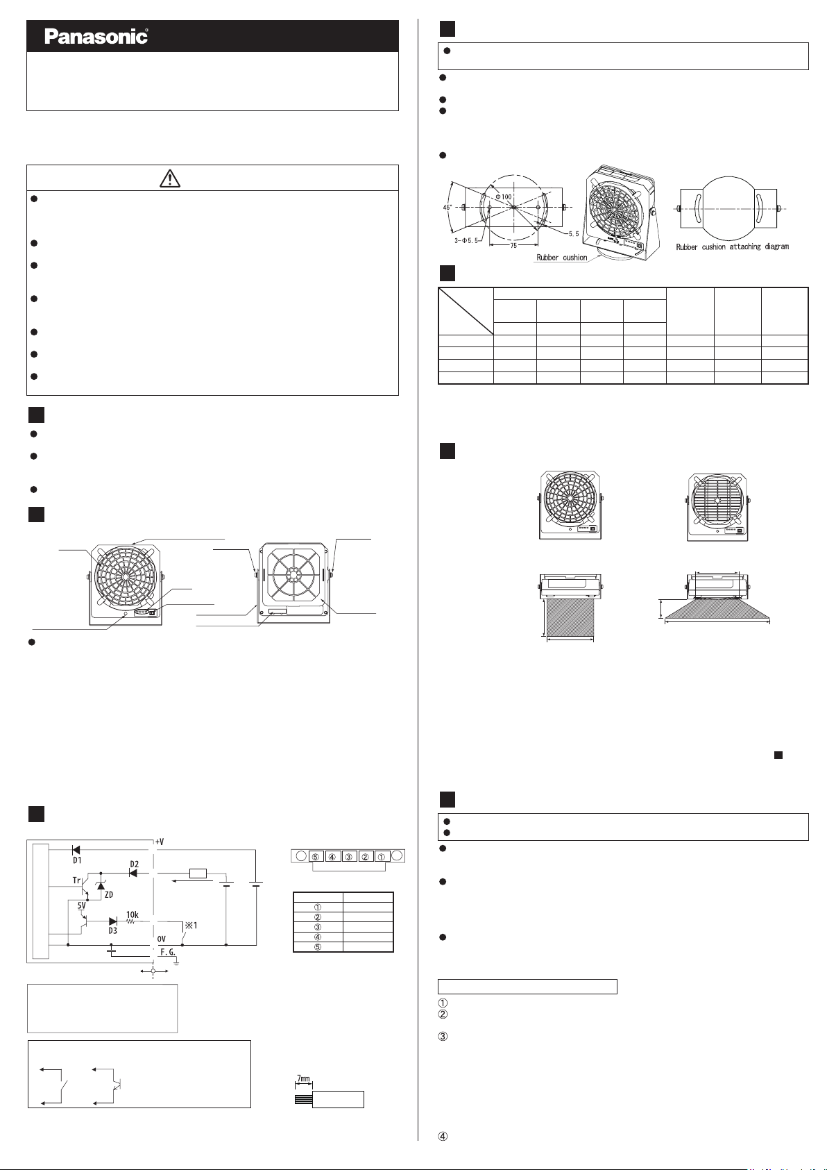
The vertical angle of the product can be freely changed by loosening the two M5
screws. After adjusting the angle, retighten the screws to secure the device so
that the angle will not change. The tightening torque for the M5 screws at this time
should be 1.2 N•m or less.
Attach the accessory rubber cushion to bracket as shown in the below diagram to
suit the usage.
5 OPERATION MATRIX
Indicators (○: Lights up, ●: Off)
POWER DSC
Normal
Discharge error
Fan error
Discharge halt input
* Once an error is detected, the error status will be maintained until the power is turned off and back
on again.
Remove the cause of the error and then turn the power back on.
If the cause of the error is not removed, the error status will continue.
* Discharge halt input is disabled when an error status is active.
6 LOUVER SELECTION
[Diagram with louver attached]
Green Green RedRed
○○●●
○●○●
○●●○
○●●●
DSC
ERROR
FAN
ERROR
Error output
(normal
Discharge
operation
close)
ON ON ON
OFF OFFOFF
OFF OFFOFF
ON OFFON
Fan
operation
2 PART DESCRIPTION
Louver
Fan speed
select switch
(Note 1)
Description of each LED
POWER ...........Lights up when the power is turned on.
(Power indicator)
DSC .................Lights up when discharge is occurring normally.
(Discharge indicator)
DSC ERROR ...Lights up when an abnormal discharge is detected.
Caution label (Note 2)
Power switch
LEDs
Bracket
Power connector
M5 screw
(Discharge error indicator)
FAN ERROR ....Lights up when a problem with fan operation is detected.
(Fan error indicator)
Notes: 1) Fan speed select switch
At the time of shipment from the factory, the device is set to fan speed 4 (MAX). Use a
Notes: 2) Caution label
Attach whichever accessory caution label is written in the appropriate language for the
fl at-tipped screwdriver to adjust the fan speed.
region of use.
M5 screw
Filter cover
3 I/O CIRCUIT DIAGRAM
②
Error output
Load
④
Main circuit
Internal circuit
Power supply reverse connection protection diode
D1 :
D2 : Output protection diode
D
: Input protection diode
3
D
Z
: Surge voltage absorption Zener diode
r
T
: NPN output transistor
*1
Non-voltage contact or
NPN transistor/open collector
or
Discharge halt input
⑤
③
①
Low (0V) : Discharge halt
High (Open) :
50mA max
Users’ circuit
Discharge (operation start)
30V
DC max
24V DC
±10%
l Option (sold separately)
ER-FAPS-J: AC adapter
l About wiring cable <Recommendation>
Compatible electric wire: AWG25#25 - 12
(Nominal cross-sectional area: 0.16 - 3.3 m
Work dimension of electric wire: 7 mm
(figure below)
* Do not solder-plate the end of the electric wire
to be wired to the connector. The tightened
screw may become loose and the wiring may be
disconnected.
(From cable insertion side)
l Pin layout
Terminal no. Terminal name
Recommended wire : AWG 25~12
F.G.
+V
0V
Error output
Discharge halt input
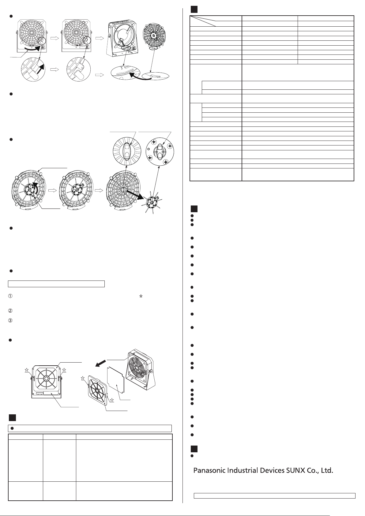
Straight louver (blue)
[Diagram of charge removal area]
1500mm
200mm
Angle louver (white) (Note 1)
200mm
700mm
600mm
This product includes two types of louver as accessories. Select the type of louver to
use based on the charge removal area.
Straight louver
This louver provides excellent direction stability for the air. It is ideal for cases where
rapid charge removal for objects is required, or when the object is some distance away.
Angle louver
This louver is excellent at dispersing the air. It is ideal for charge removal over a wide
area.
Notes: 1) The discharge needle unit is loaded on the straight louver before shipment. To replace it
with the angle louver, refer to the discharge needle unit installation procedure in "
AND MAINTENANCE
Notes: 2) If no louver is attached, the device will not turn on even when the power is supplied.
" in this manual.
7
CARE
7 CARE AND MAINTENANCE
Be sure to turn off the power before carrying out cleaning and maintenance.
The discharge needle has a sharp point, so be very careful when cleaning the needle.
If the device is used for a long period, dust and other foreign particles may
accumulate on the discharge needles or on the fan fi lter, and so the needles and
fi lter should be cleaned before use.
If the device is not cleaned regularly, the charge removal performance will drop and
operating problems or accidents may occur. Clean the device regularly, using the
following as a guide.
Discharge needle unit: Every 2 weeks
Fan intake fi lter: Every 2 weeks
The discharge needle is a consumable part. If the discharging performance is not
restored after the discharge needles have been cleaned, it is recommended that
you replace the discharge needle unit. It is recommended that you replace the
discharge needle unit after about 10,000 hours of operation.
Cleaning the discharge needle unit
Check that the power is turned off and that the fan has completely stopped.
2
)
Following the removal procedure of the louver, remove the louver from the main
unit.
Clean with the discharge needle loaded. Use a cotton swab or similar tools
moistened with alcohol to clean the discharge needles and the areas around them.
If the needles are particularly dirty, use a brush (such as a toothbrush) moistened
with alcohol to rub them clean, and then use a cotton swab to wipe them.
<When using a commercially-available ultrasonic cleaner for cleaning>
Following the removal procedure of the discharge needle unit, remove the
discharge needle unit from the louver, and immerse the discharge needle unit
into the cleaning tank to clean them. After that, dry the discharge needle unit well.
Following the installation procedure, install the discharge needle unit to the louver.
Following the installation procedure, install the louver to the main unit.
[Louver removal/installation procedure]
Louver removal procedure
Open
Turn the louver in the direction
of the arrow.
Louver installation procedure
When installing the louver to the main unit, align and insert the tongue of the
Groove of the
main unit
Remove the louver from the main unit.
Tongue of the
louver
louver into the groove of the main unit. After inserting the tongue into the groove,
turn the louver clockwise to install.
* Do not touch inside the device when removing and installing the louver, otherwise accidents
or problems with operation may occur.
[Discharge needle unit removal/installation procedure]
When using a ultrasonic cleaner for cleaning,
remove the discharge needle unit.
Discharge needle unit removal procedure
Louver (Note: 1)
Discharge
needle unit
Hold the louver and turn the discharge needle
unit counterclockwise. (Note: 2)
Discharge needle unit installation procedure
As shown in the fi gure above, install the louver and the discharge needle unit so that
Claw of the louver
Remove the discharge needle unit from the
louver to the direction shown in the figure.
Hole of the discharge
needle unit
Details of the
central part
the claw of the louver is inserted into the hole of the discharge needle unit. (Note: 3)
Turn the discharge needle unit clockwise until it stops to install.
Notes: 1) If replacing the louver, install the discharge needle unit to the replacement louver.
Notes: 2) When turning the discharge needle unit, do not apply any more force than is necessary,
otherwise the louver or the discharge needle unit may become damaged.
Notes: 3) Confi rm the side of the discharge needle unit to install. If installed on the wrong side, the
discharge needle unit or the louver may become damaged.
Option (sold separately)
ER-F12ANT : Discharge needle unit x 1
Cleaning and replacement procedure for fan fi lter
Install a fi lter in accordance with the operating environment.
Remove the fi lter cover. Disengage the clasps in the places indicated by in the illustration
below, and then pull the fi lter cover in the direction of the arrow to remove it. (Refer to the
illustration below.)
Clean away any dust and dirt adhering to the fi lter. If the fi lter is particularly dirty,
wash it in water. If washing the fi lter in water, let it dry thoroughly before reusing it.
Install the fi lter. Install the fi lter cover.
* If the device is used while the fi lter is still wet, accidents or problems with operation may occur.
* If the fi lter will not come clean, it should be replaced.
* Be careful not to let anything get inside the device while the fi lter is removed.
Option (sold separately)
ER-F12FX5
: Replacement fi lter x 5
Filter cover
Main unit
Filter
Main unit
Filter cover
8 TROUBLESHOOTING
Be sure to turn off the power before checking the discharge unit or the fan unit.
Problem Main cause Remedy
Discharge error
indicator (DSC
ERROR)
lights up.
Fan error indicator
(FAN ERROR)
lights up
.
Condensation
Foreign objects
F.G. not connected
Fan is covered
Fan is blocked
Foreign objects
• An abnormal discharge is probably occurring.
Turn off the power and check that the tip of the
discharge needle is intact and free from foreign objects,
and also check that the discharge needle unit is
correctly installed to the louver.
• If the error indicator remains lit even after the discharge
needle has been cleaned, check if the area around the
needle is dirty.
• Check that the F.G. terminal is securely grounded.
• Turn off the power and check that the fi lter is not dirty or
blocked.
• Check that there are no foreign objects inside the
product.
9
SPECIFICATIONS
Item Model No. ER-F12 ER-F12S
Charge removal time1 sec. approx. (Note 1) 1.5 sec. approx. (Note 1)
Ion balance ±10 V or less (Note 2) ±10 V or less (Note 2)
Power supply voltage 24 V DC ±10% 24 V DC ±10%
Power consumption 700 mA or less 400 mA or less
Discharge method High-frequency AC methodHigh-frequency AC method
Discharge output voltage ±2 kV approx. ±2 kV approx.
Max. fan speed 5.3 m/s (Note 2) 4.0 m/s (Note 2)
Max. fan volume 3.68 m
Error output
Output operation
Short-circuit protection
Discharge halt output
POWER Green LED (Lights up when power on)
DSC Green LED (Lights up during normal discharge)
DSC ERROR Red LED (Lights up when discharge error detected)
Indicators
FAN ERRORRed LED (Lights up when fan error detected)
Ozone generation amount 0.04 ppm or less (Note 1)
Pollution level
Ambient temperature
Ambient humidity
Vibration resistance
Over-voltage category I
Material
Grounding method
Weight 790g approx. (main unit only)
Accessories
Notes: 1) Ty pical value at 200 mm from directly in front of discharge outlet, fan speed MAX, straight
louver, with no fi lter installed.
Notes: 2) Ty pical value at 300 mm from directly in front of discharge outlet, fan speed MAX, straight
louver, with no fi lter installed.
Notes: 3) The discharge needle unit is loaded on the straight louver before shipment.
10
CAUTIONS
This product has been developed / produced for industrial use only.
Do not use this product for any purpose other than charge removal and dust removal.
Do not use this product in enviroments which are outside the specifi cation range,
otherwise operating problems or damage may occur. In addition, the operating life
of the product may become signifi cantly reduced.
Never disassemble, repair or modify this product, otherwise operating problems or
accidents may occur.
Do not dispose of this product by burning it, otherwise it may explode or toxic
fumes may be generated.
This product generates ozone, so be sure to provide adequate ventilation if using it
in a confi ned space.
Do not run the wires together with high-voltage lines or power lines or put them in
the same raceway. This can cause malfunction due to induction.
Be sure to turn off the air and the power supply before carrying out any cable
connection or inspection work. If this is not done, operating problems, damage or
electric shocks may occur.
After connecting the cables, check that the connections are correct before turning on the
power. If the cables are connected incorrectly, operating problems or accidents may occur.
Verify that the supply voltage variation is within the rating.
When using as a CSA and UL compliant product, use a CLASS 2 CSA/UL certifi ed
power supply, or a CSA/UL certifi ed power supply that has been evaluated as a
Limited Power Source as specifi ed in CAN/CSA-C22.2NO.60950-1/UL60950-1.
It takes approximately 5 seconds after the power is turned on before the fan
operation stabilizes. To ensure proper charge removal performance, do not use the
product until suffi cient time has elapsed.
Do not turn the power back on immediately after it has been turned off, otherwise
operating problems or accidents may occur. In addition, the operating life of the
product may become signifi cantly reduced. Wait at least 2 seconds before turning
the power back on again.
Do not use any cables which have any damage (such as splitting or cracking),
otherwise operating problems or accidents may occur.
Avoid using the product in places where there are high levels of steam or dust in
the air or where it might be directly exposed to water, oil or welding spatter.
Avoid use at an elevation higher than 2000m, and outdoor use.
Do not touch the discharge needle with hard objects such as tools. If the discharge
needle becomes broken, it will not provide suffi cient charge removal performance,
and moreover operating problems or accidents may occur.
Do not use this product while the fi lter is blocked, otherwise accidents or problems
with operation may occur.
Clean or replace the fi lter at regular intervals.
Be sure to turn off the power before replacing the fi lter.
Install the product so that it is at least 100 mm away from the objects being charged.
When installing this product, be sure to securely install t he m ain unit and the
bracket. If they are not securely installed or if constant vibration or shocks are
applied, accidents or problems with operation may occur.
Do not place any objects which may obstruct air fl ow within 20 mm the front of the
fan air intake, otherwise accidents or problems with operation may occur.
Use cables that are 0.15mm2 or more and 30 m or less in length for wiring.
Also, keep the wiring as short as possible in order to prevent naise.
If this product ceases functioning or is no longer required, dispose of it according to
appropriate local waste disposal regulations.
11
CSA/UL COMPLIANT PRODUCT
This product complies with CSA and UL standards, and has been certifi ed by TUV SUD.
http://panasonic.net/id/pidsx/global
Overseas Sales Division (Head Offi ce)
2431-1 Ushiyama-cho, Kasugai-shi, Aichi, 486-0901, Japan
Phone: +81-568-33-7861 FAX: +81-568-33-8591
About our sale network, please visit our website.
PRINTED IN CHINA © Panasonic Industrial Devices SUNX Co., Ltd. 2016
Type Standard fan type Low-volume fan type
3
NPN transistor/open collector
• Max. sink current: 50 mA
•
Applied voltage: 30 V DC or less (between output terminal and 0 V)
• Residual voltage: 1 V or less (at input current of 50 mA)
0 to + 50°C (No dew condensation) / Storage : -10 to + 65°C
35 to 65% RH (No dew condensation) / Storage : 35 to 65% RH
10 to 55 Hz frequency, 0.75 mm amplitude in X, Y and Z directions for two hours each
Enclosure: ABS Louver: ABS Discharge needle: Tungsten
●
/min 2.50 m3/min
OFF when discharge error or fan error detected
Normally ON
Discharge halt: Short-circuited to 0 V
Discharge (operation start): Open
Discharge needle unit: PBT Bracket: SPHC
Louvers
●
Straight louver: 1 (Note 3 )
Angle louver: 1
Incorporated
2
C (capacitor) grounding
Caution label: 1 set
Rubber cushion: 1
●
 Loading...