

Page 1
Order Number: MGCS040402C0
H21
Digital Imaging Systems
DP-1520P/1820P/1820E
[ Version 1.0 ]
WARNING
Thisserviceinformationisdesignedforexperiencedrepairtechniciansonlyandisnotintendedforusebythegeneralpublic.
Itdoesnotcontainwarningsorcautionstoadvisenon-technicalindividualsofpotentialdangersinattemptingtoserviceaproduct.
Productspoweredbyelectricityshouldbeservicedorrepairedonlybyexperiencedprofessionaltechnicians.Anyattempttoservice
orrepairtheproductorproductsdealtwithinthisserviceinformationbyanyoneelsecouldresultinseriousinjuryordeath.
© 2004 Panasonic Communications Co., Ltd.
All rights reserved. Unauthorized copying and distribution is
a violation of law.
Page 2

This Product Uses Lead (Pb) Free Solder Printed Circuit
Boards (PCBs).
Information regarding Lead-Free (PbF) solder:
Distinction of PbF PCB:
PCBs (manufactured) using lead free solder will have a mark following
the PCB part numbers in a label on the PCB.
Caution:
Pb free solder has a higher melting point than standard solder; typically
the melting point is 50 - 70 F (30 - 40 C) higher. Please use a soldering iron
with temperature control and adjust it to 700 20 F (370 10 C). Exercise care
while using higher temperature soldering irons, do not heat the PCB for too long
to prevent solder splash or damage to the PCB.
Pb free solder will tend to splash when heated too high (about 1100 F/600 C).
ECO SOLDER M705 (available from Senju Metal Industry Co., Ltd.:
URL: http://www.senju-m.co.jp) is recommended when repairing PbF PCBs.
The contents of this Service Manual and the Specifications are subject to change
without notice.
Panasonic Communications Co., Ltd. reserves the right to make improvements in
the product design without reservation and without notice.
Published in Japan.
2
Page 3
ImportantNotice
PleasereadthisnoticecompletelyBEFOREinstallinganyoptional
accessories.Asfailuretoproperlyinstalltheadditionalboardor
connectorwiththepowerONcoulddamagethemachine'sSPCor
SCboard.
Pleasefollowtheinstructionsbelow:
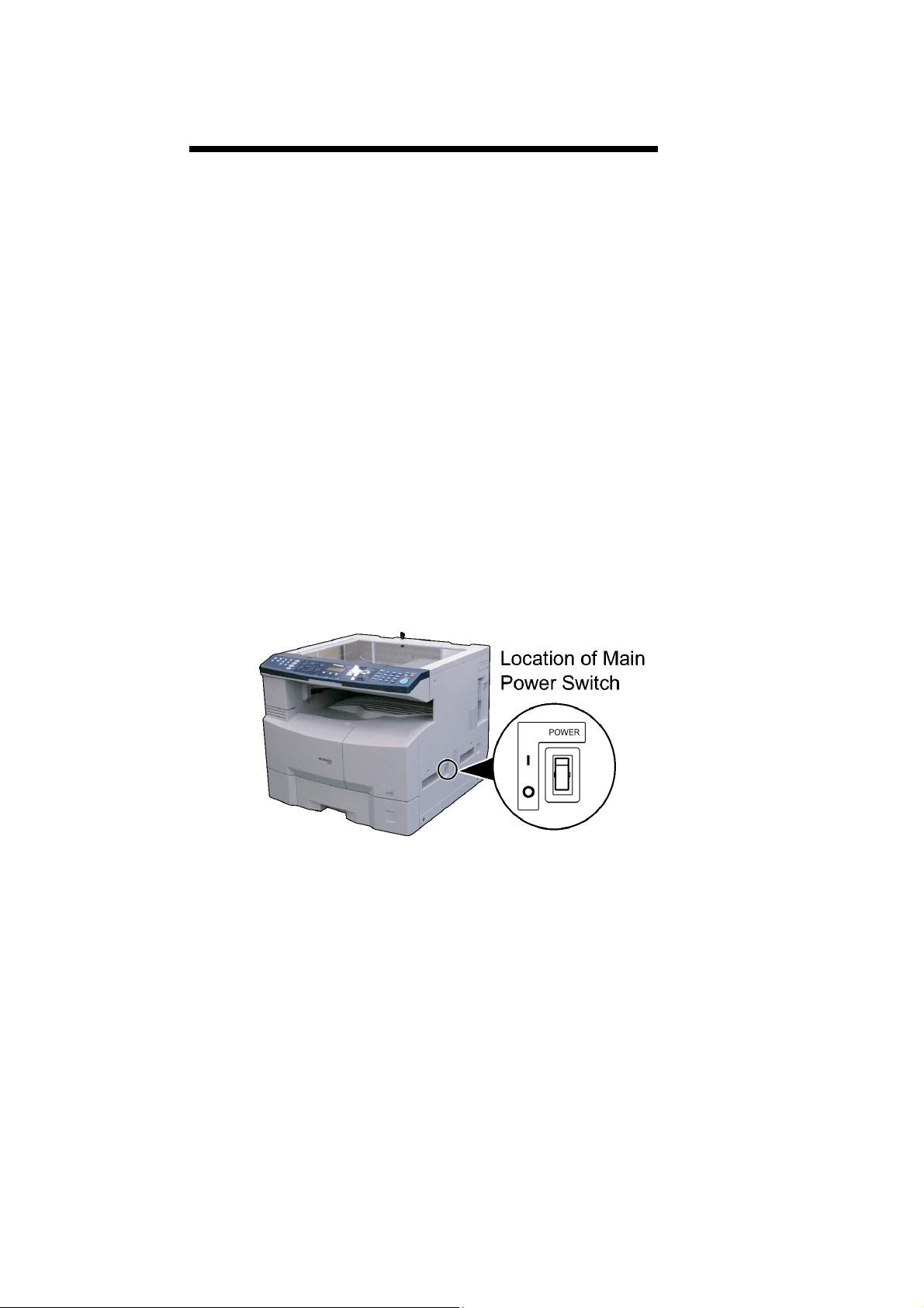
1.ItisessentialthatyouturnOFFtheMainPowerSwitchlocated
ontheRightSideofthemachine.
2.ItisessentialthatyouunplugtheACPowerCordfromthewall
outlet.(DuringaLightningStorm,topreventelectrocution
disconnecttheTelephoneLineCablefirstbeforeunpluggingthe
ACPowerCord,iftheFaxoptionisinstalled.)
3.Pleasereadtheinstallationinstructionscarefullyandfolloweach
step.
<Example:DP-1820E>
Note:
O=PowerOFF,l=PowerON
Note:
IftheHardDiskDriveUnitisinstalled,topreventaScanDiskFunctionfrombeing
performed(similartoWindowsOSwhenthepowerisabruptlyinterrupted),itis
importanttofollowthestepsequencebelowwhenturningOFFthePowerSwitchonthe
machine.
1.Ifthemachineisinthe"ENERGYSAVER(ShutdownMode)",youmayturnthePowerSwitchonthe
RightSideofthemachinetotheOFFposition.Ifitisnotinthe"ENERGYSAVER(ShutdownMode)",
continuetostep2below.
2.Press"FUNCTION"and"ENERGYSAVER"keyssimultaneouslyfirst.
3.Waitapproximately10secondswhilethemachinewritestheclosingstatusontotheHardDiskDrive
Unitandadvancesinto"ENERGYSAVERMODE".
4.TurnthePowerSwitchontheRightSideofthemachinetotheOFFposition.
5.UnplugtheACPowerCord.(DuringaLightningStorm,topreventelectrocutiondisconnectthe
TelephoneLineCablefirstbeforeunpluggingtheACPowerCord,iftheFaxoptionisinstalled.)
*Thespecificationsaresubjecttochangewithoutnotice.PanasonicCommunicationsCo.,Ltd.reserves
therighttomakeimprovementsintheproductdesignwithoutreservationandwithoutnotice.
3
Page 4
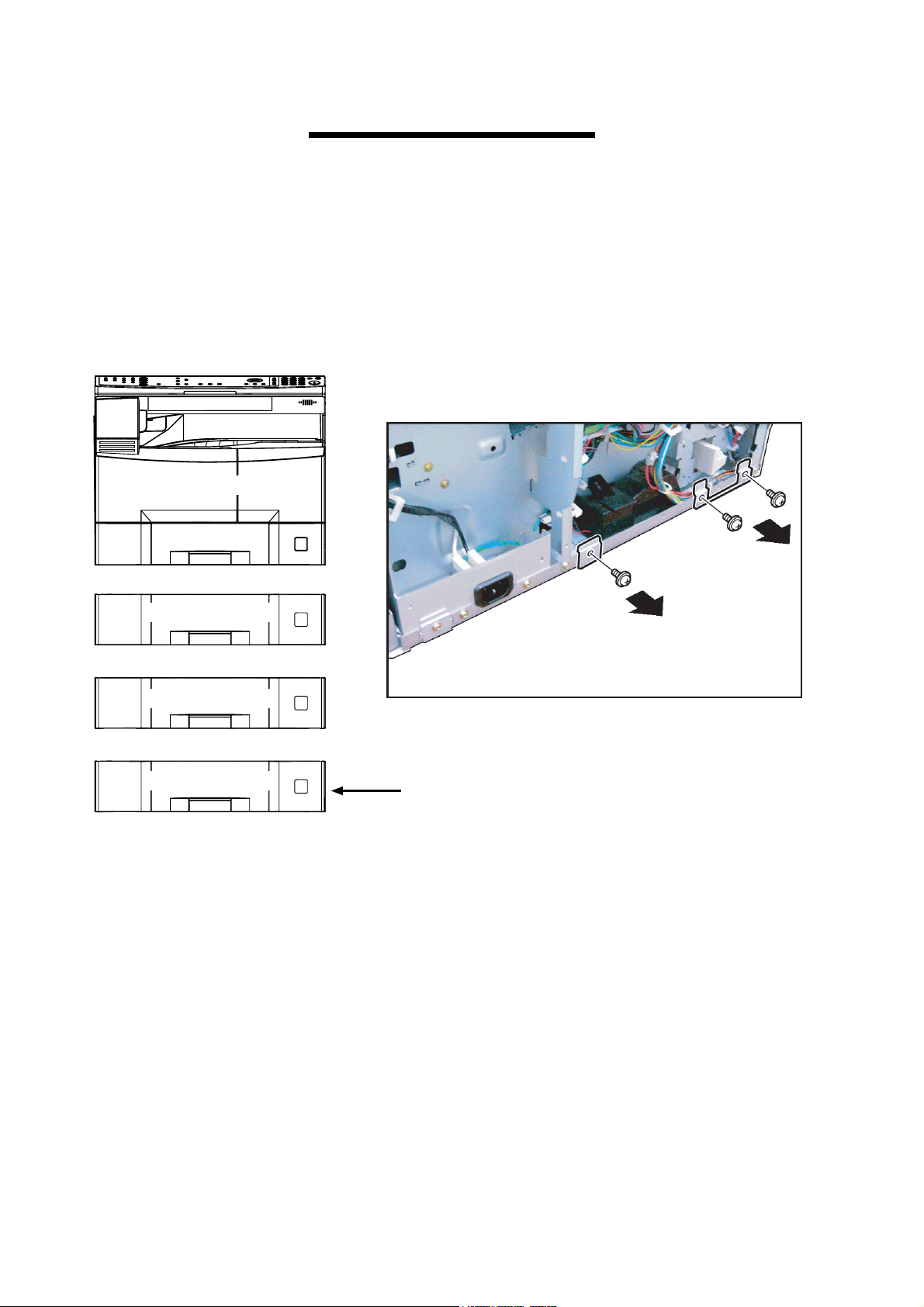
Important
Before installing optional Paper Tray(s), ensure the two (2)
Brackets located on the Rear of the Copier and each
preceding Paper Tray is removed first.
MainUnit
2ndPaperTray
3rdPaperTray
4thPaperTray
Donotremovethesebrackets
fromthebottomPaperTrayof
yourconfiguration.
Note: It is not necessary to remove these brackets from
the bottom Paper Tray of your configuration or the
Copier if it is being placed on a Plain Stand.
4
Page 5
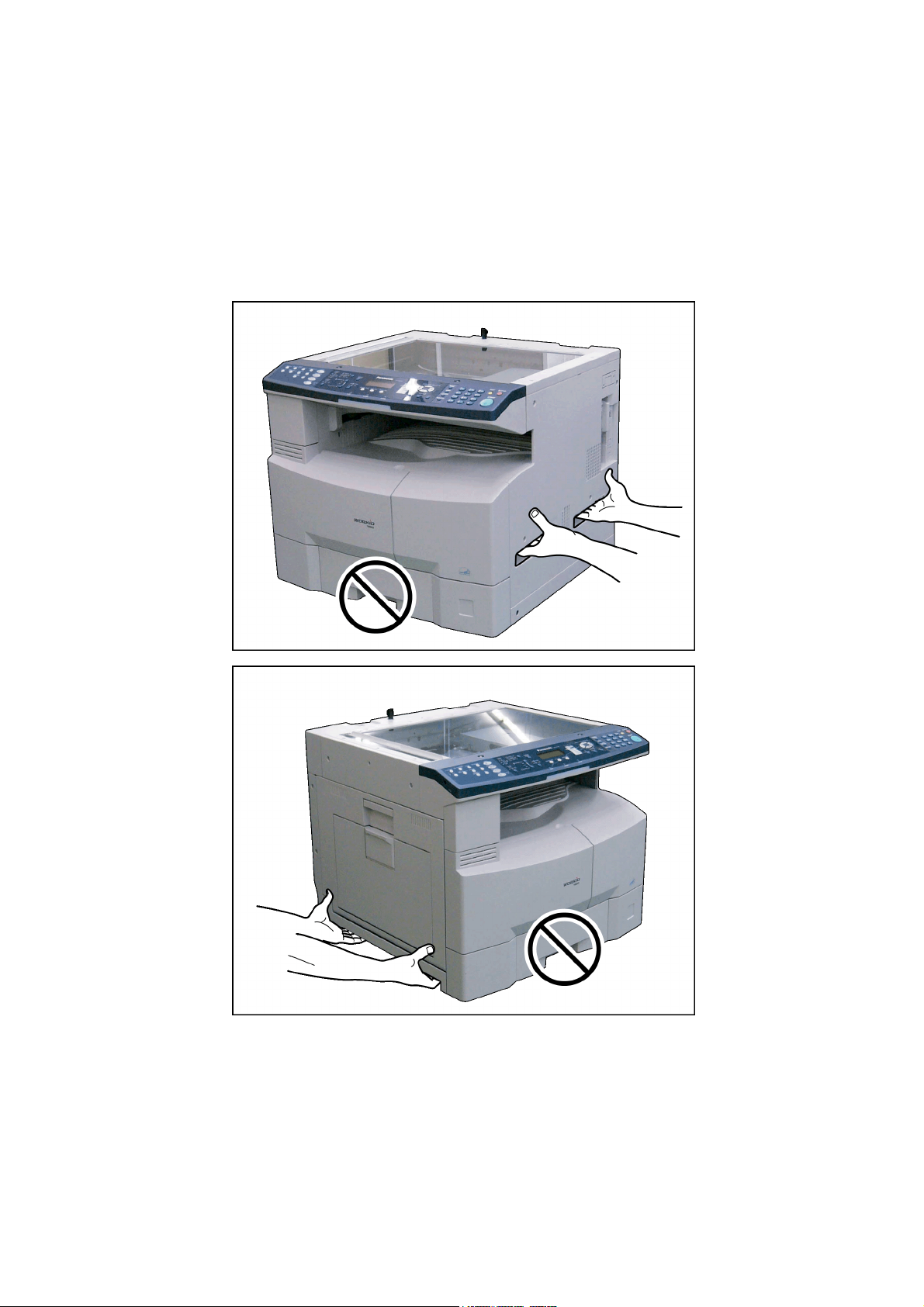
Caution:
Dependingonyourmachine'smodel,itmayweightapproximately93.26-98.33
lb(42.3-44.6kg)withoutanyoptions.
Topreventinjuries,usetheappropriatenumberofpersonnelandliftormove
themachineasillustrated.
DonotliftthemachinebythePaperTrayasitmaycausedamageand/orbodily
injury.
Note:
RefertotheInstallationInstructionswheninstallingthemachine.
5
Page 6
P
e
t
F
T
m
P
T
I
e
P
recautions
or Your Safety
o prevent severe injury and loss of life, read this section carefully before servicing the Panasonic
achine to ensure proper and safe operation.
lease ensure that the machine is installed near a wall outlet and is easily accessible.
his section explains the graphic symbols used in the machine and/or this manual.
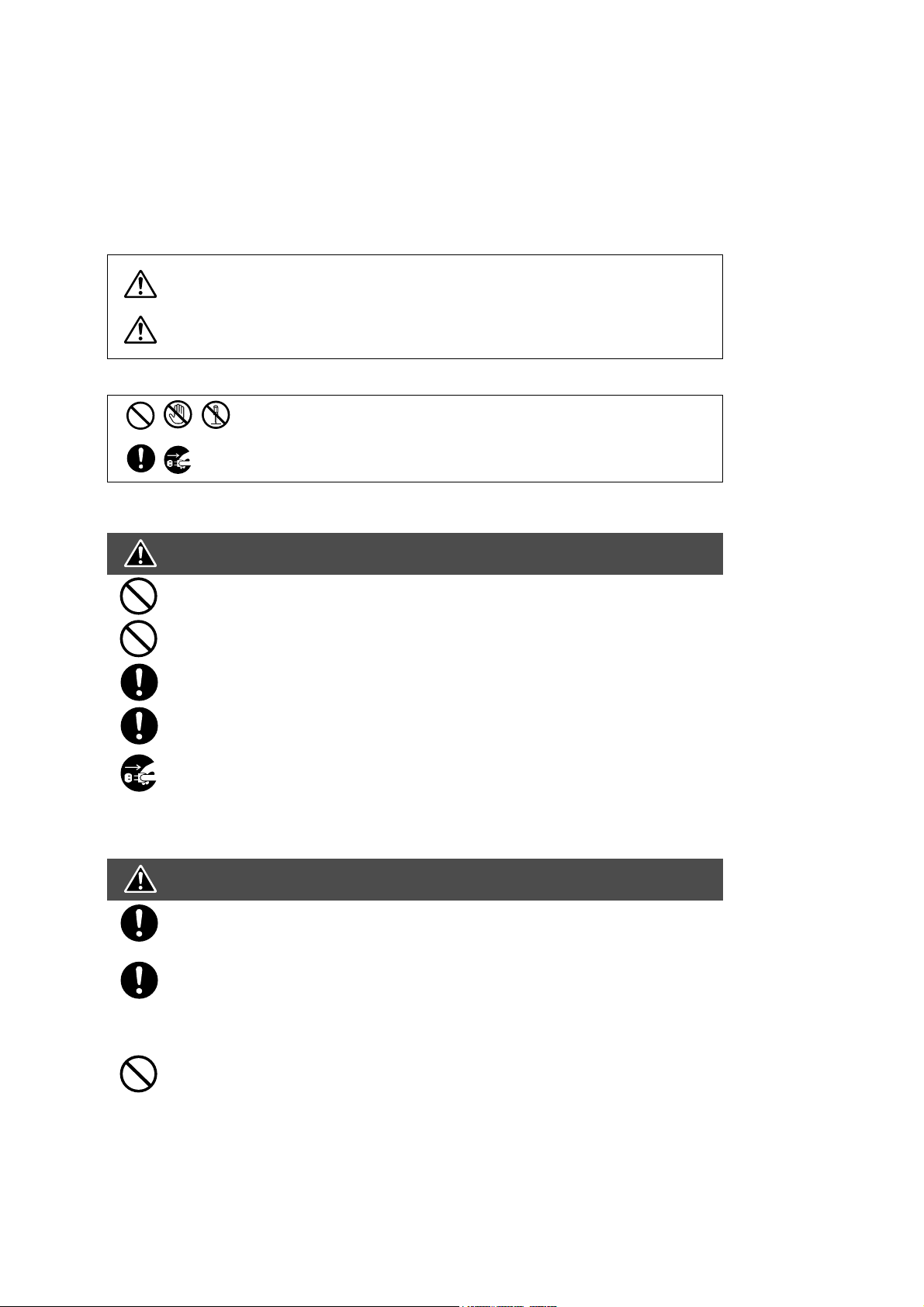
WARNING:
Denotes a potential hazard that could result in serious injury or death.
CAUTION:
Denotes hazards that could result in minor injury or damage to the machine.
This section also explains the graphic symbols used in the machine and/or this manual.
These symbols are used to alert operators to a specific operating procedure
that must not be performed.
These symbols are used to alert operators to a specific operating procedure
that must be emphasized in order to operate the machine safely.
nstallation and Relocation Cautions
CAUTION
Do not place the machine near heaters or volatile, flammable, or combustible materials
such as curtains that may catch fire.
Do not place the machine in a hot, humid, dusty or poorly ventilated environment.
Prolonged exposure to these adverse conditions can cause fire or electric shocks.
Place the machine on a level and sturdy surface that can withstand.
If tilted, the machine may tip-over and cause injuries.
When relocating the machine, remove the toner and/or developer, and pack the machin
with proper packing materials for shipping.
When moving the machine, be sure to unplug the power cord from the outlet. If the
machine is moved with the power cord attached, it can cause damage to the cord which
could result in fire or electric shock.
ower and Ground Connection Cautions
WARNING
Ensure that the plug connection is free of dust. In a damp environment, a contaminated
connector can draw a significant amount of current that can generate heat and
eventually cause fire over an extended period of time.
Always use the power cord provided with your machine. When an extension power cord
is required, always use a properly rated cord.
120 V/15 A or AC 220 - 240V/10 A
If you use a cord with an unspecified current rating, the machine or plug may emit smok
or become hot to the touch externally.
Do not attempt to rework, pull, bend, chafe or otherwise damage the power cord. Do no
place a heavy object on the cord. A damaged cord can cause fire or electric shocks.
6
Page 7

Never touch a power cord with wet hands. Danger of electric shock exists.
y.
O
O
If the power cord is broken or insulated wires are exposed, replace immediately with a specified cord onl
Using a damaged cord can cause fire or electric shocks.
Stop operation immediately if your machine produces smoke, excessive heat, unusual noise, or smell,
or if water is spilt onto the machine. These conditions can cause fire. Immediately switch Off and
unplug the machine.
Do not disconnect or reconnect the machine while it is on. Disconnecting a live connector can deform
the plug and cause fire.
When disconnecting the machine, grasp the plug instead of the cord. Forcibly pulling on a cord can
damage it and cause fire or electric shock.
When the machine is not used over an extended period of time, switch it Off and unplug it. If an unused
machine is left connected to a power source for a long period, degraded insulation can cause electric
shocks, current leakage or fire.
Be sure to switch Off and unplug the machine before accessing the interior of the machine for cleaning,
maintenance or fault clearance. Access to a live machines interior can cause electric shock.
Be sure to switch Off and unplug the machine before accessing the interior of the machine for
accessing interface cables, maintenance or fault clearance. Access to a live machines interior can
cause electric shock.
Once a month, unplug the machine and check the power cord for the following. If you notice any
unusual condition.
The power cord is plugged firmly into the receptacle.
The plug is not excessively heated, rusted, or bent.
The plug and receptacle are free of dust.
The cord is not cracked or frayed.
thers
The machine has a built-in circuit for protection against lightning-induced surge current. If lightning strikes in your
neighborhood, switch Off the machine. Disconnect the telephone line cable first, then unplug the power cord from
the machine and reconnect only when the lightning storm has stopped.
If you notice flickering or distorted images or noises on your audio-visual units, your machine may be causing
radio interference. Switch it Off and if the interference disappears, the machine is the cause of the radio interference. Perform the following procedure until the interference is corrected.
Move the machine and the TV and/or radio away from each other.
Reposition or reorient the machine and the TV and/or radio.
Unplug the machine, TV and/or radio, and replug them into outlets that operate on different circuits.
Reorient the TV and/or radio antennas and cables until the interference stops.
For an outdoor antenna, ask your local electrician for support.
Use a coaxial cable antenna.
perating Safeguards
WARNING
Do not touch areas where these caution labels are attached to the surface may be very hot, and cause
server burns.
Do not place any liquid container such as a vase or coffee cup on the machine. Spilt water can cause
fire or shock hazard.
Do not place any metal parts such as staples or clips on the machine. If metal and flammable parts get
into the machine, they can short-circuit internal components, and cause fire or electric shocks.
If debris (metal or liquid) gets into the machine, switch Off and unplug the machine.
Operating a debris-contaminated machine can cause fire or electric shock.
Do not try to alter the machine configuration or modify any parts. An unauthorized modification can
cause smoke or fire.
7
Page 8

t
n
s
CAUTION
C
e
Do not place a magnet near the safety switch of the machine. A magnet can activate the
machine accidentally resulting in injuries.
Do not use a highly flammable spray or solvent near the machine. It can cause fire.
When copying a thick document, do not use excessive force to press it against the
document glass. The glass may break and cause injuries.
Never touch a labeled area found on or near the heat roller. You can get burnt. If a shee
of paper is wrapped around the heat roller, do not try to remove it when it is hot, to avoid
injuries or burns. Switch Off the machine immediately, and wait until it cools down.
Do not use conductive paper, e.g. folding paper, carbonic paper and coated paper. Whe
a paper jam occurs, they can cause a short circuit and fire.
Do not place any heavy object on the machine. An off-balance machine can tip-over or
the heavy object can fall, causing damage and/or injuries.
Keep the room ventilated when using the machine for an extended period of time to
minimize the ozone density in the air.
When copying with the document cover open, do not look directly at the exposure lamp.
Direct eye exposure can cause eye fatigue or damage.
Pull out paper trays slowly to prevent injuries.
When removing jammed paper, make sure that no pieces of torn paper are left in the
machine. A piece of paper remaining in the machine can cause fire. If a sheet of paper i
wrapped around the heat roller, or when clearing a jammed paper that is difficult or
impossible to see, do not try to remove it by yourself. Doing so can cause injuries or
burns. Switch Off the machine immediately, and wait until it cools down.
onsumable Safeguards
WARNING
Never throw a toner bottle into an open flame. Toner remaining in the bottle can
cause an explosion and you can get burnt.
Never throw toner or a waste toner container or a toner bottle into an open flame. It
can cause an explosion and you can get burnt.
Keep button batteries out of the reach of children. If a button battery is swallowed
accidentally, get medical treatment immediately.
CAUTION
Never heat the drum cartridge, or scratch its surface. A heated or scratched drum can b
hazardous to your health.
Do not mix new and old batteries together. Otherwise, batteries can burst or leak,
causing fire or injuries.
Be sure to use the specified type of batteries only.
Ensure that batteries are installed with correct polarity. Incorrectly installed batteries can
burst or leak, resulting in spillage or injuries.
8
Page 9

Table of Contents
Specifications Table................................. 10
1.1. Copy Function.........................................10
1.2. Fax, Printer and Internet
Fax Functions .........................................20
1.3. System Combination...............................30
1.4. Options List.............................................31
Maintenance, Adjustments and
Check Points............................................ 32
2.1. Preventive Maintenance .........................32
2.2. Required Tools .......................................34
2.3. Preventive Maintenance Points ..............35
2.4. Preventive Maintenance
Check List ...............................................37
2.5. Resetting the P/M
(Preventive Maintenance) Counter .........39
2.6. Lubrication Point List ..............................40
2.7. Updating the Firmware ...........................41
2.8. Copy Quality Adjustment
Procedure (Order)...................................50
2.9. Adjusting the Printer Registration,
LSU Image Side to Side .........................53
Troubleshooting .......................................57
3.1. Error Codes (For Copier) ........................57
3.2. Information Codes Table
(For Facsimile)........................................67
5.16. Inverting Automatic Document
Feeder (For DP-1820E) ....................... 188
5.17. PC Boards/Harnesses.......................... 204
5.18. 2nd/4th Paper Tray .............................. 210
5.19. 3rd Paper Tray ..................................... 216
5.20. Packing and Accessories ..................... 222
5.21. Printer Controller Module
for PCL6 ............................................... 226
5.22. Printer Controller Module
for PS/PCL6 ......................................... 228
5.23. Network Scanner Module..................... 230
5.24. Internet Fax/E-Mail Module .................. 232
5.25. Fax Communication Board................... 234
5.26. Keyboard Option .................................. 236
5.27. Hard Disk Drive Unit............................. 238
5.28. Accounting Software ............................ 240
5.29. i-ADF Packing and Accessories........... 242
5.30. ADF Packing and Accessories ............. 244
5.31. 2nd/4th Paper Tray and
3rd Paper Tray Packing and
Accessories.......................................... 246
5.32. Dehumidifier Heater Kit
(For Main Unit) ..................................... 248
5.33. Dehumidifier Heater Kit
(For Optional Paper Tray(s)) ................ 250
5.34. Key Counter Harness Kit ..................... 252
5.35. Hardware Identification Template ........ 254
Service Modes .........................................73
4.1. Service Modes (For Copier)....................73
4.2. Service Modes (For Facsimile) .............100
Exploded View & Parts List.................... 130
5.1. Destination Codes ................................131
5.2. Cover Assembly....................................132
5.3. Scanner Unit .........................................136
5.4. Control Panel Unit.................................140
5.5. Paper Transportation ............................144
5.6. Automatic Duplex Unit ..........................148
5.7. Electrical Parts......................................152
5.8. Frame Parts ..........................................156
5.9. Fuser Unit .............................................160
5.10. Hopper Unit...........................................164
5.11. Developer Unit ......................................166
5.12. Drum Unit..............................................170
5.13. Drive Unit ..............................................174
5.14. Paper Tray ............................................178
5.15. Automatic Document Feeder ................180
Alphanumerical Parts List...................... 257
9
Page 10
1 Specifications Table
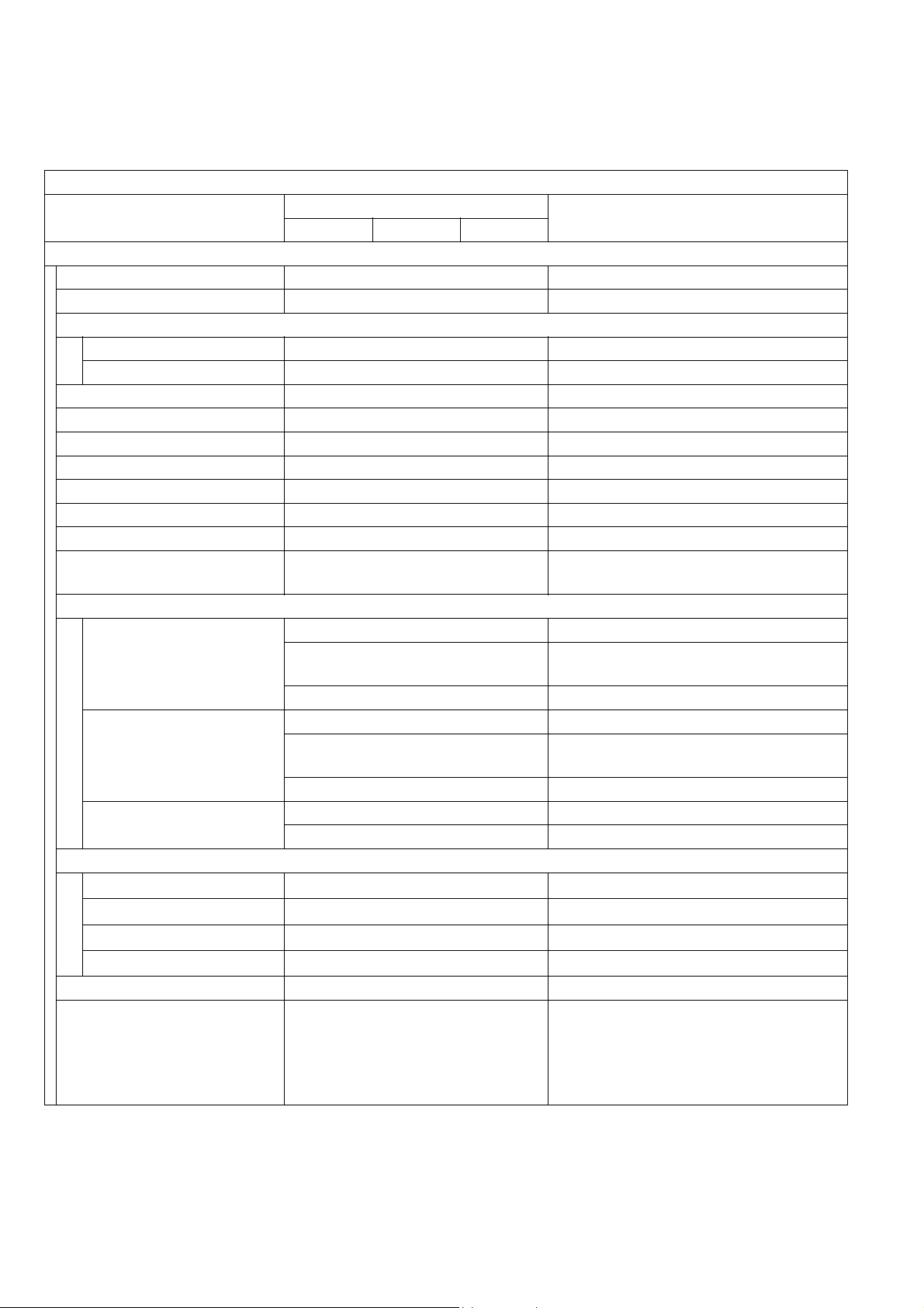
1.1. Copy Function
Copy Function
Items
DP-1520P DP-1820P DP-1820E
Basic Specifications
1 Type Desktop
2 Platen Fixed
3 Original Position
Platen Left / Rear
ADF / i-ADF Left / Center
4 Recording Paper Path Center
5 Face Up / Face Down Face Down
6 Drum Organic Photo Conductor (OPC)
7 Copy Process Dry Electrostatic System
8 Developing Process Dry Dual Components
9 Toner Recycle No
10 Fusing System Heat & Pressure
11 Max Original Size
12 Paper Size
LDR, LGL, LTR, LTR-R, INV-R For USA and Canada
Paper Tray
A3, A4, A4-R, A5, A5-R, B4, FLS
A3, A4, A4-R, B4, B5, B5-R For Other Destinations
LDR, LGL, LTR, LTR-R, INV-R For USA and Canada
Bypass Tray
A3, A4, A4-R, A5-R, B4, FLS
A3, A4, A4-R, B4, B5, B5-R For Other Destinations
Bypass Tray (Envelope)
13 Paper Weight
Paper Tray
Bypass Tray
ADU
ADF / i-ADF
14
Warm-up Time Less than 30 sec 68 °F (20 °C)
0.13 - 0.20 lb (60 - 90 g/m
0.12 - 0.29 lb (55 - 133 g/m
0.14 - 0.20 lb (64 - 90 g/m
0.11 - 0.24 lb (50 - 110 g/m
15
First Copy Time Less than 6.9 sec
Description
Ledger (11 x 17 in) /
A3 (297 x 420 mm)
For EU
FLS = 8 x 13 in, 8.5 x 13 in
For EU
FLS = 8 x 13 in, 8.5 x 13 in
#10 (4.1 x 9.5 in) For USA and Canada
DL (4.3 x 8.7 in) For EU
2
)
2
)
2
For DP-1820E only
)
2
)
From Platen, Letter/ A4 Portrait, 1st
Paper Tray. Period between Start Key
is pressed and Paper ejected to the
Exit Tray.
When LSU is ready.
DP-1520P/1820P/1820E
Remarks
Ver. 1. 0
10
JUN 2004
Page 11
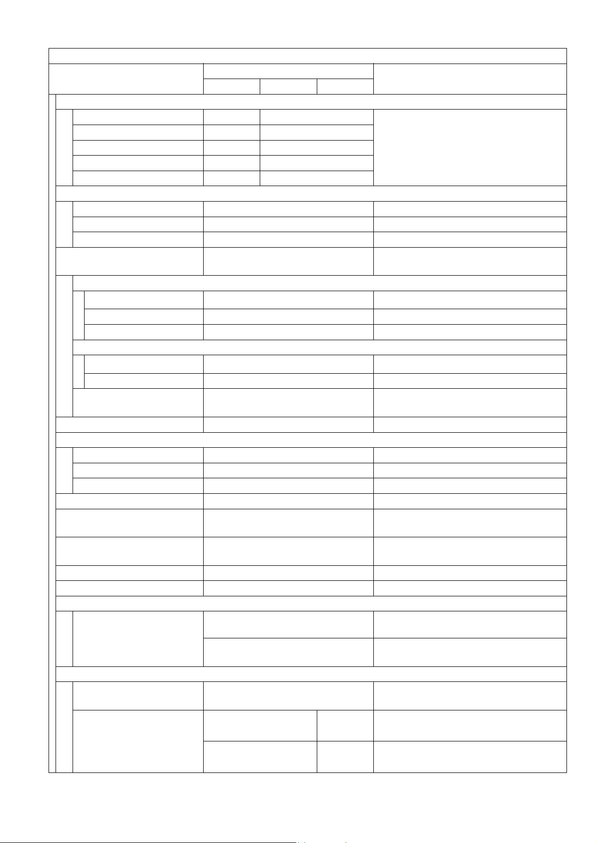
Copy Function
Items
Description
Remarks
DP-1520P DP-1820P DP-1820E
16 Copy Speed
Ledger / A3 9 cpm 11 cpm
Legal / B4 / FLS 10 cpm 12 cpm
Letter-R / A4-R 12 cpm 15 cpm / 14 cpm
Letter / A4 15 cpm 18 cpm
From Platen, Letter/A4 Portrait, 1st
Paper Tray, and Paper ejected to the
Exit Tray, LSU is ready, and
Continuous Copy.
Invoice-R / A5-R 15 cpm 18 cpm
17
Zoom
Enlargement Selected Original size / Copy size
Reduction Selected Original size / Copy size
Zoom 50 - 200% 1% Step
18 Paper Feed
Front Loading Universal Paper
Tray
Paper Tray
Capacity
550 sheets x 1
LTR / A4 : 20 lb (75 g/m
Auto Size Setting No Control Panel Selectable
Low Level Warning Empty Only
Bypass Paper Tray
Capacity 50 sheets
LTR / A4 : 20 lb (75 g/m
Auto Size Setting Yes
Paper Capacity
(Std. Configuration)
600 sheets
Paper Tray 1 (Std) +
Bypass Paper Tray
19 Multi Copy Range 999 sheets
20 Gradation
Te xt B i- Le ve l
Text / Photo 256 steps Halftone by Error Diffusion
Photo 256 steps
21
Resolution 600 dpi Scanning and Printing.
Standard Sorting Memory
22
Size
Standard Page Memory
23
Size
Exit Tray Capacity
24
Standard: 250 sheets
16 MB
32 MB
25 Color No
26 Dimensions
(W x D x H)
22.0 x 21.9 x 18.1 in
(558 x 557 x 460 mm)
33.2 x 24.6 x 24.5 in
(844 x 624 x 623 mm)
H: To Platen Glass.
Includes ADF / Bypass Paper Tray.
27 Operating Space
(W x D)
93.26 lb (42.3 Kg)
33.2 x 22.2 in
(844 x 565 mm)
95.46 lb
(43.3 Kg)
Includes Bypass Paper Tray.
For USA and Canada
Weight
96.12 lb (43.6 Kg)
98.33 lb
(44.6 Kg)
For EU and Other Destinations
DP-1520P/1820P/1820E
2
)
2
)
Ver. 1. 0
11
JUN 2004
Page 12
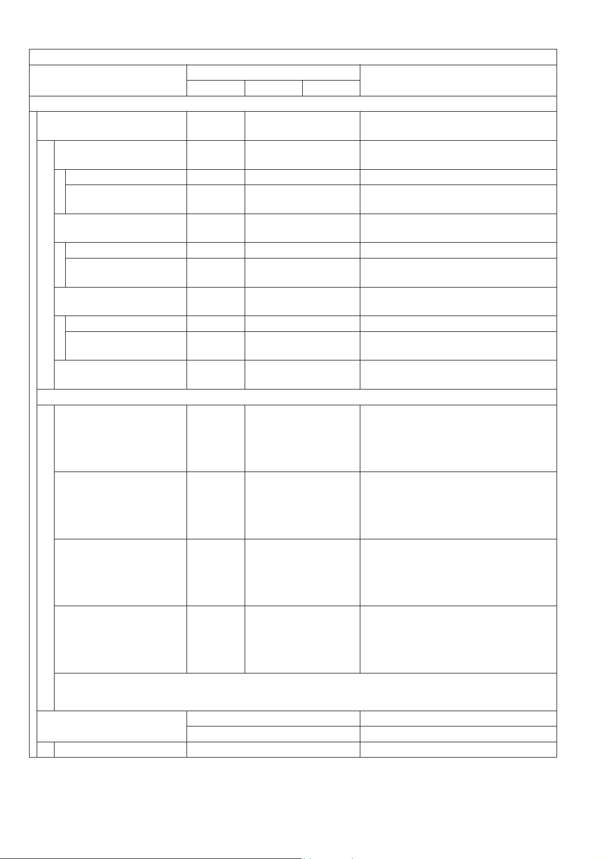
Copy Function
Items
Description
DP-1520P DP-1820P DP-1820E
Options
1 Paper Feed System
550 sheets 2nd
Paper Tray
550
sheets x 1
550 sheets x 3
Yes Yes Motor is not mounted.
Paper Size Detection Manual Manual Control Panel Selectable
Low Level Paper
Warning
550 sheets 3rd
Paper Tray
Empty
Only
No
Empty Only
Yes Motor is mounted.
Paper Size Detection - Manual Control Panel Selectable
Low Level Paper
Warning
550 sheets 4th
Paper Tray
-
No
Empty Only
Yes Motor is not mounted.
Paper Size Detection - Manual Control Panel Selectable
Low Level Paper
Warning
Max. Paper Capacity
-
1,150
sheets
Empty Only
2, 250 sheets
LTR / A4 : 20 lb (75 g/m
2Stand
Low Stand with Casters
Stand for
4*-Paper Tray
Configuration
No Option
DA1D18C : For USA and Canada
DA-DA191-PE : For Other
Low Stand with Casters
Stand for
3*-Paper Tray
Configuration
No Option
DA1D18C : For USA and Canada
DA-DA190-PE : For Other
Mid Stand with Casters
Stand for
2-Paper Tray
Configuration
Option Option
DA1D18B : For USA and Canada
DA-DA189-PE : For Other
High Stand with Casters
Stand for
1-Paper Tray
Configuration
Option Option
DA1D18A : For USA and Canada
DA-DA188-PE : For Other
Note:
The same Stand (DA1D18C) is used for either 3 or 4 Paper Tray Configuration for USA and
Canada.
3Platen Cover
Option
Standard
For USA and Canada
For EU and Other Destinations
Free Stop Yes From 30 to 70 degrees.
DP-1520P/1820P/1820E
Remarks
2
)
Only
Destinations
Only
Destinations
Only
Destinations
Only
Destinations
Ver. 1. 0
12
JUN 2004
Page 13
DP-1520P/1820P/1820E
Copy Function
Items
Description
Remarks
DP-1520P DP-1820P DP-1820E
4ADF
Single Side Type Option
Original Set Face Up
Scanning Method Sheet Through
Capacity (Originals) 50 sheets
LTR / A4 : 20 lb (75 g/m
2
)
SADF Mode Yes
Free Stop Yes From 30 to 70 degrees.
5 Inverting ADF (i-ADF)
Duplex Type
No
Option
Original Set - Face Up
Scanning Method -
Capacity (Originals)
SADF Mode
-
-
Sheet
Through
50 sheets
Yes
LTR / A4 : 20 lb (75 g/m
2
)
Available for single side scanning only.
Free Stop - Yes From 30 to 70 degrees.
6 Exit Tray (Inner)
Tray Position Inner
Number of Bins 1
Face Up / Face Down Face Down
Bin Capacity 250 sheets
Multi Tray Function
No
Shift Tray Function No
7 Finisher No
8 Exit Tray (Outer) No
11 Automatic Duplex Unit No Standard
12 Counter
Key Counter Capability
Option
The Harness Kit contains only
Harnesses, Bracket and a Screw.
13 Dehumidifier Option Supplied as a Service Part.
14 Sorting Image Memory
Optional Image Memory 1
(16MB)
Optional Image Memory 2
(64MB)
Optional Image Memory 3
(128MB)
Yes
Yes
Yes
Unit comes standard with 16 MB.
1-Slot available for an Optional Image
Memory module.
Additional Optional Sorting Image
15 Hard Disk Drive Option
Memory (Minimum 16 MB) is required
for the Hard Disk Drive to function.
(For Tandem, Remote Copy, etc.)
Ver. 1. 0
13
JUN 2004
Page 14
Copy Function
Items
Description
DP-1520P DP-1820P DP-1820E
Features
1 Automatic Features
Auto Magnification
Selection
Yes
Auto Paper Selection Yes
Auto Paper Tray
Selection
Yes
Auto Start Yes
Remote Diagnostic
Machine Stops when Out
of Toner
Yes
Yes PPC Function
2 Additional Features
Low Level Paper Warning Empty Only
Photo Mode Yes 256 steps
Original Detection
Release
No
Edit / Effects
Book Mode Yes
Edge Mode Yes
Margin Mode Yes
X-Y Zoom No
Stamping /
Page Numbering
Inverse Mode
(Negative / Positive)
No
No
Centering Mode Yes
Image Repeat Yes
Mirror Mode No
Others (Inverting ADF & ADU)
2-Page Copy Mode Yes
2 in 1 Yes
4 in 1 Yes
6 in 1 No
8 in 1
Booklet Mode
No
No
DP-1520P/1820P/1820E
Remarks
Using ADF only
Reservation while Power On
Initializing.
Requires the Fax Communication
Board (DA-FG180) option or the
Internet Fax / E-MAIL Module
(DA-NF180) option.
Manually overridden when using the
Original Size keys.
With Digital Sky Shot
LDR → LTR x 2
(A3 → A4 x 2, B4 → B5 x 2)
Copy from four 1-Sided
pages to 1 Booklet Mode
sheet.
Ver. 1. 0
14
JUN 2004
Page 15
Copy Function
Items
Description
DP-1520P DP-1820P DP-1820E
Duplex Copy
1→2No
2→1
Yes Yes
2→2No
Book→2No
Yes
Yes
Yes
Scanning twice by turning the original.
1st Page BLANK No 1 → 2/2 → 1/2 → 2
1st Page IMAGE No Book → 2
Image Rotation (90 or
270 °)
Yes
Electronic Sorting Yes
Rotation Sorting Yes
Insertion Job
Cover Mode No
Page Insertion Mode No
OHP Interleave Mode No
Presentation Mode No
Department Counter Yes 300 Departments
ADF
Multi Size Feed
JOB Build and SADF
Mode
No
Yes
Original Counter No
Job Memory Yes 2 Jobs in Memory
Job Time Display Yes
Concurrent Copy
Yes 12 Concurrent Copy Jobs
Tandem Copy Mode No
Remote Copy Mode No
Scan Once Print Many
Mode
Yes
Job Complete Notice No
Trial Copy Mode No
Weekly Timer No
Function Mode Yes
Interrupt Yes
Electronic Counter Yes
Digital Sky Shot Mode Yes
Double Exposure Yes
3 Control Panel
Display LCD 20 digits x 2 lines
GREEN : Scanning /
Status Lamp Yes
RED : Alarm / Warning
DP-1520P/1820P/1820E
Remarks
Printing
Ver. 1. 0
15
JUN 2004
Page 16
Copy Function
Items
Description
Remarks
DP-1520P DP-1820P DP-1820E
Key
Original Size Yes
Copy Size Yes
Keypad Yes
Clear Yes
Stop Yes
Start Yes
Energy Saver Yes
Multi Size Feed No
Sort Yes
Function Mode Yes
Original Detection
Release
No
Interrupt Yes
Reset Yes
One-Touch key Yes With Keyboard Option
Mode Change No Yes
Copier / Printer / NW Scanner / Fax
and Internet Fax Mode
LCD Main Indication
Message Language
(Default)
Original Size / Image
Indication
Paper Size / Image
Indication
English (American) For USA and Canada
Specified Language
For EU and Other Destinations
Yes
(without Image)
Yes
(without Image)
Paper Tray Selection Yes
Selected Paper Tray /
Tray Status
Original Mode
Selection
Yes
Yes
Text / Text-Photo / Photo
Copy Density Selection Yes
Setting Confirmation Yes
Function Classification Yes
Zoom Magnification Yes
Number of Copies Yes
JOB Build and SADF /
Multi Size Feed Mode
Yes
Error Code Yes
Finishing
No
Warning Indicators Yes
Add Toner Yes
Toner Waste
Container Full
Add Paper (No
Yes
Yes
Paper)
Add Paper
(Under 50 sheets)
No
DP-1520P/1820P/1820E
Ver. 1. 0
16
JUN 2004
Page 17
Copy Function
Items
Description
Remarks
DP-1520P DP-1820P DP-1820E
Paper Jam Indication Yes
Paper Jam Location Yes
Service Alert Call Yes
User Error Yes
Machine Error Yes
History of Jam Errors Yes
4 Main Unit
Total Counter
Electronic Yes
Standard for EU.
Mechanical Yes
Available as a Service Part for Other
Destinations.
Max. Weight of
Documents on the Platen
11.02 lb (5 kg)
Glass
ADF with Document
Guide
Yes
Clip Pocket Yes
Operating Instructions
Pocket
No
Warning / Caution Label Specified Language
5 Optical System
Original Detection
Method
Reflective Photo Sensor Type
Scanning Method 600 dpi CCD
Dehumidifier Yes Supplied as a Service Part
Mechanical Multi Copy
Mode
No
6 Process System
Type
Toner 10 K
Separate OPC Unit and
Developer Unit Type
User replacement
Toner Waste Container 10 K
Drum Life 60 K
Developer Life 60 K
Dehumidifier Yes Supplied as a Service Part
Manual Add Toner Yes
Manually adds toner to the developer
(up to TDC threshold)
Efficiency
1 Productivity
ADF Productivity (LTR /
A4)
ADU Copy Productivity
(LTR / A4)
100%
Throughput when the LSU is ready;
-55%
Paper is fed from the 1st Paper Tray
and is ejected to the Exit Tray.
DP-1520P/1820P/1820E
Ver. 1. 0
17
JUN 2004
Page 18
DP-1520P/1820P/1820E
Copy Function
Items
Description
Remarks
DP-1520P DP-1820P DP-1820E
PM Cycle
1PM Cycle
Major PM 120 K
Minor PM (Cleaning) 60 K
Packing Configuration
1 Packing Dimension
2 Packing Weight
28.5 x 28.6 x 34.1 in
(724 x 727 x 866 mm)
28.4 x 28.4 x 29.5 in
(722 x 722 x 750 mm)
121.25 lb
(55 kg)
127.87 lb
(58 kg)
112.44 lb
(51 kg)
123.46 lb
(56 kg)
130.07 lb
(59 kg)
114.64 lb
(52 kg)
For USA, Canada and China
For EU and Other Destinations
For USA and Canada
For China
For EU and Other Destinations
3 Accessories
Process Unit Yes
Developer No
To ne r No
Toner Waste Container No
Operating Instructions Yes
Power Supply
1 Power Requirement
99 - 132 VAC 47 - 63 Hz
Single phase
180 - 264 VAC 47 - 63 Hz
Single phase
120 VAC
220 - 240 VAC
2 Power Consumption
Max.Power Consumption
100 VAC PS Less than 1.3 KW
220 VAC PS Less than 1.3 KW
Standby
100 VAC PS 120 W
220 VAC PS 120 W
Turns On the Heater Power.
Energy Saver Automatically enters the Sleep or
Power Saver Mode
100 VAC PS 19.0 W
220 VAC PS 19.5 W
Sleep Mode
100 VAC PS 8.5 W
220 VAC PS 9.5 W
Shutdown Mode after 10 minutes from
the Standby or Energy Saver Mode.
Manually enters the Energy Saver
Mode by pressing the Energy Saver
key.
Sleep or Shutdown mode is controlled
by the General Functions setting.
Shutdown Mode
100 VAC PS 1.4 W
Network Function not available
220 VAC PS 1.6 W
Ver. 1. 0
18
JUN 2004
Page 19

Copy Function
Items
Description
DP-1520P DP-1820P DP-1820E
Ambient Conditions
1 Temperature 50 - 80 °F / 10 - 30 °C
2 Relative Humidity 30 - 80%
3 Safety
UL1950-1 / CSA C22.2 No.950 For USA and Canada
EN60950-1
4 Energy Saver Energy Star Compliant
Class A computing device in FCC
Rules Part 15
5EMI
Class B
EN55022, EN55024,
EN61000-32, EN61000-3-3
6 Lead Free Solder (PbF)
This Product uses Lead Free
(PbF) PCBs
DP-1520P/1820P/1820E
Remarks
For EU and Other Destinations
For USA and Canada
For EU
Refer to the Parts Manual for details
Ver. 1. 0
19
JUN 2004
Page 20
DP-1520P/1820P/1820E
1.2. Fax, Printer and Internet Fax Functions
1.2.1. Fax Function
Fax Function
Items
Main Specifications
1 Compatibility G3 ITU-T Std & Non-Std
2 PSTN Line Port Yes 1-Line Only
3 Leased Line Port No
4 V.24 Line Port No
5 Modem Speed 33.6 - 2.4 kbps T.30/V.34/V.17/V.29/V.27ter
6 Coding Scheme JBIG/MMR/MR/MH
7 ECM Yes Conforms to ITU-T Rec. T.30 ECM
8 Short Protocol Yes (B, D)
9 Transmission Speed
Transmission
Std. : 203 x 98 (8 x 3.85)
Fine : 203 x 196 (8 x 7.7)
S-Fine : 203 x 391 (8 x 15.4)
Communication Resolution
10
dpi x lpi (pels/mm x lines/
mm)
600dpi : 600 x 600 dpi
Reception
Std. : 203 x 98 (8 x 3.85)
Fine : 203 x 196 (8 x 7.7)
S-Fine : 203 x 391 (8 x 15.4)
600dpi : 600 x 600 dpi
Scanner Mechanism
1 Scanning Device CCD (ADF / Platen)
2 Scanning Speed (ADF)
Resolution Vertical Horizontal
Std: 203 x 98 (8 x 3.85)
dpi x lpi (pels/mm x lines/
mm)
0.9 / 1.0 sec 0.7 sec
Fine: 203 x 196 (8 x 7.7)
dpi x lpi (pels/mm x lines/
mm)
S-Fine: 406 x 391 (16 x
15.4) dpi x lpi (pels/mm x
1.8 / 2.0 sec 1.4 sec
lines/mm)
600dpi: 600 x 600 2.8 sec 2.1 sec
3 Scanning Speed (Platen)
Resolution Vertical Horizontal
600dpi: 600 x 600 2.8 sec 2.1 sec
Std. : 203 x 98 (8 x 3.85)
Scanning Resolution
4
dpi x lpi (pel/mm x lines/
Fine : 203 x 196 (8 x 7.7)
S-Fine : 203 x 391 (8 x 15.4)
mm)
600dpi : 600 x 600 dpi
Description
DP-1820P / 1820E
Approx. 2.9 sec
406 x 391 (16 x 15.4)
406 x 391 (16 x 15.4)
406 x 391 (16 x 15.4)
Remarks
ITU-T Image No. 1
(A4, Std Resolution)
600 dpi communication is only
possible between T.30 Compliant
Panafax, WORKiO, and other T.30
compliant machines.
LTR / A4, Scanned in Vertical or
Horizontal Direction.
Excluding Initializing Time and ADF
slipping factor.
Ver. 1. 0
20
JUN 2004
Page 21
Fax Function
Items
Description
Remarks
DP-1820P / 1820E
5 Document Size (Max.) ADF: LDR / A3
6 Effective Scanning Width LDR (11.5 in) / A3 (292 mm)
7 A3 size TX/RX Yes Conforms to ITU-T A3
8 Reduction XMT Yes
9 ADF Capacity 50 sheets
LDR to LTR / A3 to B4 / A3 to A4
/ B4 to A4
Face-Up, feed from top page
LTR / A4 (20 lb / 75 g/m
10 Collation Stack Yes Face Down
Printer Mechanism
1 Recording Method LP
2 Recording Speed
23 / 30 ppm
(A4 Horizontal)
Recording Speed attained after the 1st
copy.
3 Recording Resolution Fax 600 x 600 dpi
Invoice : Not supported.
Ledger size is transmitted as A3 size
4 Recording Paper Size
Ledger / Legal / Letter /
A3 / B4 / A4 / A5
for N. American models. If A3 is
received, approx. 1" of image on both
edges are not printed on Ledger size
paper.
5 Effective Printing Width 11.4 in (289 mm) Conforms to ITU-T A3
6 Recording Paper Capacity 600 sheets
Optional max. 2250 sheets
LTR / A4 : 20 lb (75 g/m
7 Collation Stack Yes Face Down
8 Consumable
Toner Bottle, Developer,
OPC Drum
Fax Memory
1 Standard Memory 2 MB (120 pages)
Optional Memory
2
4 MB
8 MB
Flash ROM, ITU-T Image No.1
(A4, Std Resolution)
Expansion Flash Memory Card, using
ITU-T Image No.1 (A4, Std Resolution)
Dual Operation
1 Multi Task Operation Yes
2 Direct XMT Reserve Yes
3 Memory XMT Reserve Yes
Number of Memory Job
4
Files
Yes Max. 50 files
Dialing/Telephone Features
1 One-Touch Keys 28
Requires Optional Keyboard.2 One-Touch / Program Keys 4
3 One-Touch Auto Dialers 32
4 Abbr. Auto Dialers 200
Plus an additional 800 stations
5 Total Auto Dialers 232
available to select from, when the
optional Hard Disk Drive (DA-HD18) is
installed.
6 Directory Search Dialing
7
Max. Tel Number Digits 36
Yes
DP-1520P/1820P/1820E
2
)
2
)
Ver. 1. 0
21
JUN 2004
Page 22

DP-1520P/1820P/1820E
Fax Function
Items
Description
Remarks
DP-1820P / 1820E
8 Max. Station Name
Characters
Full Number Dialing
9
(Buffered Dialing)
10 Direct Dialing
(Monitor Dialing)
15
Yes Max. 50 stations
Yes Voice mode
11 Automatic Redialing Yes Up to 15 times at 0 to 15 min. intervals
12 Manual Redialing Yes Pressing the REDIAL/PAUSE button
13 Line Monitor Speaker Yes
14 Chain Dialing (Hybrid Dial) Yes In Monitor Dialing mode only
15 Pulse / Tone Dialing Yes 10 pps / DTMF
16 Pulse to Tone Change No
17 Flash Key Yes
18 Handset No
Transmission Features
1 Direct Transmission Yes
2 Memory Transmission Yes Page Retransmission
Quick Memory
3
Transmission
Multi-Station Transmission
4
(Sequential Broadcasting)
Direct Deferred
5
Transmission
Yes
Yes Max. 250 stations
No ADF Deferred Transmission
6 Deferred Transmission Yes Max. 50 timers
Deferred Multi-Station
7
Transmission
Yes
8 Priority Direct Transmission Yes Priority ADF Transmission
Priority Memory
9
Transmission
No
10 Batch Transmission Yes Real Time (up to 5 Files)
90 Degree Rotation
11
Transmission
Yes
12 Cover Sheet Yes
13 Confidential Mail Box No
14 Multi-Copy Transmission No
FAX : Back-up with Flash Memory.
15 Memory Back-Up Yes
Copy / Printer : No Back-up with DRAM
16 Duplex Scanning Yes With Inverting ADF (i-ADF)
Reception Features
1 Substitute Reception Yes
LTR/A4/LGL: 70 - 100%
2 Fixed Reduction Yes
(in 1% Steps),
Top & Left Alignment
LTR/A4/LGL: 70 - 100%
3 Auto Reduction Yes
(in 1% Steps),
Top & Left Alignment
Ver. 1. 0
22
JUN 2004
Page 23

DP-1520P/1820P/1820E
Fax Function
Items
Description
Remarks
DP-1820P / 1820E
4 Overlap Printing Yes Page End Approx. 0.51 in (13 mm)
5 Receive to Memory Yes
Distinctive Ring Detector
6
(DRD)
90 Degree Rotation
7
Reception
No
Yes
8 Duplex Printing Yes
Polling
1 Polling Yes
2 Turnaround Polling No
3 Multi-Station Polling Yes
Max. 250 stations
4 Deferred Polling Yes Max. 50 timers
Deferred Multi-Station
5
Polling
Yes Max. 50 timers / 250 stations
6 Direct Polling Tx No
7 Memory Polling Tx Yes 1 File
8 Preset Polling Password Yes
Temporary Polling
9
Password
Yes
10 Continuous Polling Yes
Convenience
1 Panel Display LCD
2 Voice Contact No
3 Edit File Mode Yes With View Mode
4 Incomplete File Save Yes With View Mode
5 Automatic Cover Sheet Yes
Certainty
1 Verification Stamp Yes
2 Header / Total Page Print Yes
3 Transaction Journal Yes 200 Transactions / with View Mode
4 Comm. Journal Yes With Image Data
5 Last Ind. XMT Journal Yes
List Printouts
1 One-Touch List 2 ABBR. No. List 3 Program List Yes
4 Address Book Search List Yes Auto Dialer List
5 Fax Parameter List Yes
6 File List Yes With View Mode
7 Ind. XMT Journal Yes
8Directory Sheet No
Ver. 1. 0
23
JUN 2004
Page 24

DP-1520P/1820P/1820E
Fax Function
Items
Description
Remarks
DP-1820P / 1820E
Identifications
1 Logo Yes 25 Characters
2 Multiple Logo No
3 Character ID Yes 16 Characters
4 Numeric ID Yes 20 Digits
Special Communications
1 Password XMT / RCV No
2 Selective Reception No TSI Check
3 Relay XMT Request No
4 Relay XMT Center No
5 Confidential XMT / Polling No
6 Confidential Center No
7 Mailbox XMT / Polling No
8 Mailbox Center No
9File XMT No
10 Fax Forward Yes
Received File Transfer
(Only with Internet Fax Option)
11 Sub-Address XMT Yes T. Routing
12 Sub-address RCV No
13 OMR-XMT No
Standards
FCC Part 68 For USA
1 PSTN
Industry Canada CS-03 For Canada
TBR 21 For EU
Others
1 Fax Access Code Yes
2 PIN Code Access Yes For USA and Canada only
3 Intelligent Redial (AI) Yes 5 Files
4 Department Code Yes 300 Departmental Codes
5 Power Saver Mode Yes
6 Self Diagnostic Function Yes
Remote Diagnostic
7
Function
Yes
8 Check & Call Function Yes
9 V.24 / Encryption Interface No
Ver. 1. 0
24
JUN 2004
Page 25
DP-1520P/1820P/1820E
1.2.2. Printer Function
Printer Function
Items
DP-1520P / 1820P / 1820E
Interface
1
Centronics Parallel I/F No
2LAN (Network)
3 USB Port Yes USB
4 IEEE-1394 No
Printer Function
LDR, LGL, LTR, LTR-R, INV-R For USA and Canada
1 Printing Size
A3, A4, A4-R, A5, A5-R, B4, FLS For EU
A3, B4, A4, A4-R, B5, B5-R For Other Destinations
2 Bypass Paper Tray Yes
3 Stapling No
4 Printing Resolution (dpi)
Max. 1200 (Equivalent) x 600 dpi
5 Interface
6OS
7 Printer Work Memory Size 20 MB Not expandable
8GDI Yes
9
PDL (PCL6) Yes Requires Optional PCL6 Emulation Kit.
10 PDL (PS3) Yes
11
Duplex Printing Yes
12 Collation Stack Yes
13 Status Monitor
Network Yes
USB No
14 Network Printing Yes
15 Smoothing Yes
16 Applicable PC IBM PC, AT or Compatible, MAC MAC is PS only.
17 Multi-Task Operation
Printing while Fax-XMT
from Memory
Printing while Fax-RCV
into Memory
Fax-XMT from Memory
while Printing
Fax-RCV into Memory
while Printing
Output to separate tray for
18
Printing, Fax, Copy
Description
Ethernet 10Base-T/
100Base-TX
USB / Ethernet
Win 98 / Win Me /
Win NT 4.0 / Win 2000 /
Win XP / MAC 8.6-10.1
Yes
Yes
Yes
Yes
No
Remarks
Selectable 600 dpi, with Smoothing,
the results are similar to PS3 / PCL6
Printers (1200 dpi Equivalent).
MAC 8.6-10.1 is PS only.
Requires Optional PS / PCL6
Emulation Kit
DP-1820E only.
Custom Size/Post Card Size is not
available.
Ver. 1. 0
25
JUN 2004
Page 26

Printer Function
Items
Description
DP-1520P / 1820P / 1820E
19 Font Yes
20 Mailbox Yes
21 Secure Mailbox Yes
DP-1520P/1820P/1820E
Remarks
Requires Optional PCL6 or PS / PCL6
Emulation Kit
Requires Optional HDD Unit.
Max. 100 Users.
Max. 20 mailboxes for each User ID
Requires Optional HDD Unit.
Max. 100 Users.
Max. 20 mailboxes for each User ID
Ver. 1. 0
26
JUN 2004
Page 27

DP-1520P/1820P/1820E
1.2.3. Network Scanner Function
Network Scanner Function
Items
Interface
1 Centronics Parallel I/F No
2 LAN (Network)
3 USB Port No
4 IEEE-1394 No
Network Scanning Function
1 Scanning Device CCD (i-ADF / ADF / Platen)
Scanning Speed
2
(ADF / I-ADF)
3 Halftone 256 Halftone shades With Error Diffusion
4
Max. Document Size Ledger, A3
Scanning Resolution
5
(dpi)
6OS
Win NT 4.0 / Win 2000 / XP
7 2-Sided Scanning Yes With i-ADF.
8 File Format Mult-page TIFF / PDF
9 Completion Notice Yes
10 Protocol TCP/IP, Non-Std
Network Address Features
1 One Touch Address Keys
2 Abbr. Address Numbers 60 Independent for Network Scanner
Description
DP-1820P / 1820E
Ethernet 10Base-T/
100Base-TX
600 x 600 : 2.1 sec
300 x 300 : 1.1 sec
150 x 150 : 1.1 sec
600 x 600
300 x 300
150 x 150
Win 98 / Me /
32
Remarks
Letter / A4
Selectable, 600 dpi Optical Scanner
TIFF can also be converted to PDF
with the PDMS Software
Auto Pop-up on the PC Screen
(requires WEB Status Monitor)
Requires Optional Keyboard.
Shared with Fax/Internet Fax
One Touch Address, 32 in Total
Ver. 1. 0
27
JUN 2004
Page 28
1.2.4. Internet Fax Function
Internet Fax Function
Items
Main Specifications
1 Communication Protocols SMTP / POP3 / MIME
2 Max. Modem Speed NA
3 Coding Scheme JBIG/MMR/MR/MH
4 File Format TIFF / PDF
5 Line Interface RJ-45 Ethernet LAN
Scanner Mechanism
1 Max. Document Size Ledger, A3
2 Effective Scanning Width 11.4 in (289 mm)
Std. : 203 x 98 (8 x 3.85)
Scanning Resolution
3
dpi x lpi (pel/mm x lines/mm)
Fine : 203 x 196 (8 x 7.7)
S-Fine : 203 x 391 (8 x 15.4)
600dpi : 600 x 600 dpi
Printer Mechanism
1 Printing Resolution 600 dpi
2 Effective Recording Width 11.4 in (289 mm)
Transmission Features
1 Multi-Task Operation Yes
2 Memory Transmission Yes
Sequential Multi-Station
3
Transmission
Simultaneous Multi-Station
4
Transmission
5 Sender Selection Yes
G3 / Email Mixed
6
Broadcasting
7 Deferred Transmission Yes
8 Fax Forward Yes
9 Sub-address RCV Yes
10 Mail Header
Email Header Print Selection Yes All or From / To / Subject only
Subject Line Random Entry
Description
DP-1820P / 1820E
406 x 391 (16 x 15.4)
Yes
Yes
Yes
Remarks
Selectable
PDF file is only available if sending to
PC (Network Scanner).
LAN: 600 dpi, 16 x 15.4 Scanning
Resolution is available with
Parameter setting
Simultaneous operation of G3 Fax and
LAN is available.
Max. 250 stations
(200 Address Book + 50 Full Number
Dialing)
Received File Transfer, only with
Internet Fax Option
Inbound Routing, only with Internet
Fax Option
DP-1520P/1820P/1820E
Ver. 1. 0
28
JUN 2004
Page 29

DP-1520P/1820P/1820E
Internet Fax Function
Items
Description
Remarks
DP-1820P / 1820E
LAN Features
1 Internet Fax Communication Yes
A3 Communication is available with
Parameter setting.
2 Internet Mail Reception Yes
3 Internet Fax Server Features
Internet Fax Relay XMT Yes Internet Fax → Internet Fax → G3FAX
Email Relay MXT Yes PC → Internet Fax → G3FAX
Received Fax / Email
Forward
Yes Local print available
PC to FAX Transmission No
Inbound Routing Yes
Phone Book Registration from
PC
Internet Fax Parameters
4
Registration via Email
Yes Via E mai l
Yes
Using Sub-Address.
Local print available
5 Internet Delivery Confirmation Yes With MDN
6 Network Scanning Yes 600 dpi
7 Network Printing
LPR / LPD Yes 600 dpi
GDI Yes 600 dpi
PDL Yes
Requires Optional PCL6 or PS
Emulation Kit
8 DHCP Client Yes
9 LDAP Yes Lightweight Directory Access Protocol
10 TIFF Viewer Yes Selectable, PDMS / TIFF Viewer
Certainty
1 Comm. Journal (w / Image) Yes
ID
1 Email Address Yes
Ver. 1. 0
29
JUN 2004
Page 30
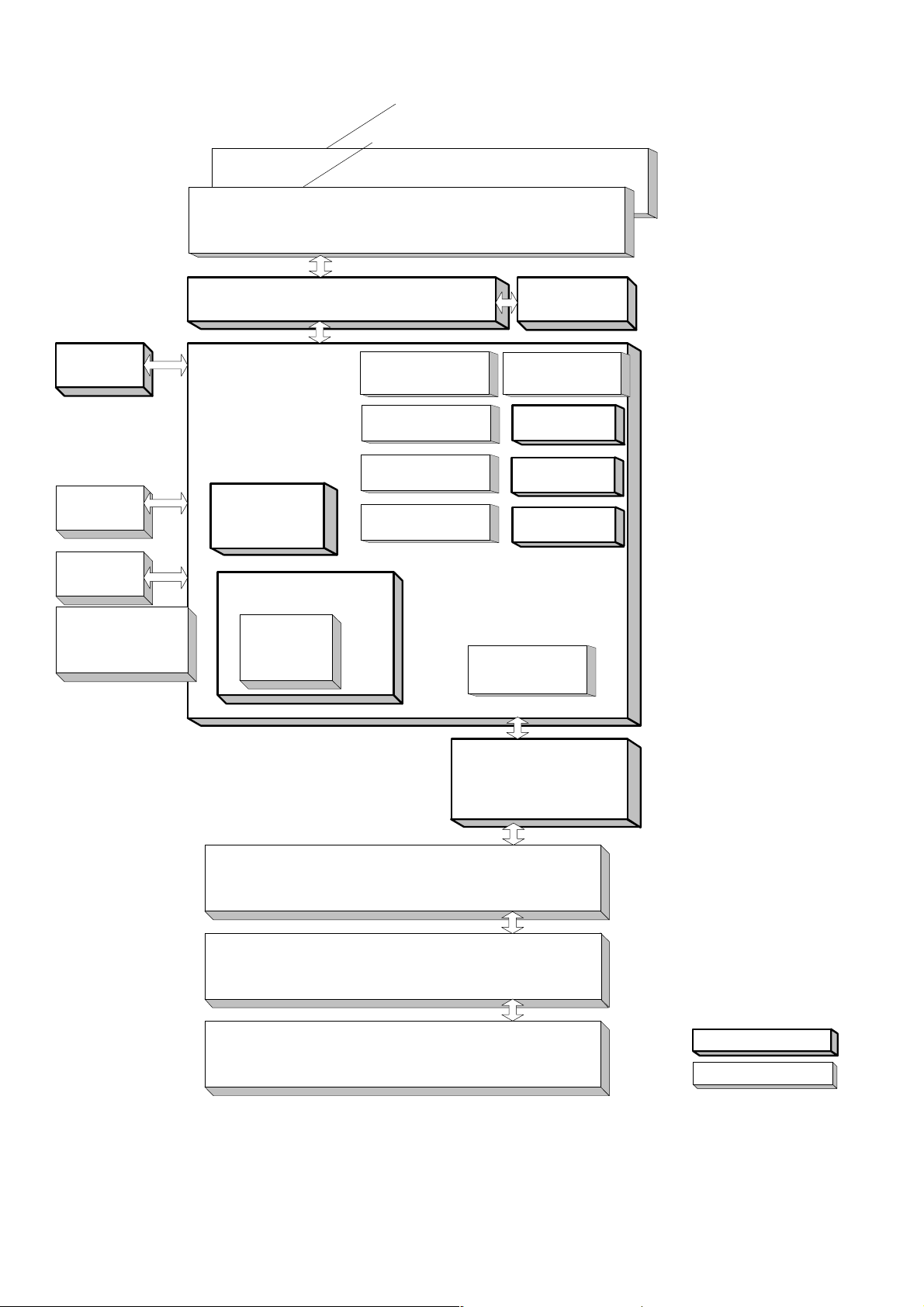
1.3. System Combination
ADF PC Board
DP-1520P/1820P/1820E
ADF
Inverting ADF (DP-1820E only)
Panel
(PNL PC Board)
Key Counter
Harness Option
Dehumidifier
Heater Kit
Expansion Flash
Memory Card
4 or 8M
Scanner Unit
(SPC PC Board)
Main PC Board
(SC PC Board)
Automatic
Duplex Unit
(DP-1820E only)
Electronic Sorting Memory
Image Memory
16, 64, 128MB
Either Option
PCL6
Emulation Option
PS/PCL6
Emulation Option
Network
Scanner Option
Internet Fax/
E-Mail Option
Document Sensor
Motor
Fax Communication
Option (FXB/MJR)
Printer
USB
Interface
10/100 Ethernet
Interface
Hard Disk
Drive Option
2nd Paper Tray (CST2 PC Board)
3rd Paper Tray (CST3 PC Board)
4th Paper Tray (CST2 PC Board)
SPC PC Board
Standard Configuration
Option
Ver. 1. 0
30
JUN 2004
Page 31

DP-1520P/1820P/1820E
1.4. Options List
■ Options
Option Name Option Number Remarks
Printer Controller Module (PCL) DA-PC180 Printer Controller for PCL6*
Multi Page Description Language
Controller Module (PCL/PostScript)
Network Scanner Module DA-NS180 For Network Scanning
Internet Fax / E-Mail Module DA-NF180 Internet Fax/Email Communication
Fax Communication Board DA-FG180 G3 Fax Communication
Keyboard Option DA-KB180
Hard Disk Drive Unit DA-HD18
Expansion Board DA-EM600 F-ROM Board (8 MB)
Expansion Flash Memory Card, 4 MB UE-410047
Expansion Flash Memory Card, 8MB UE-410048
Image Memory (16MB) DA-SM16B
Image Memory (64 MB) DA-SM64B
Image Memory (128MB) DA-SM28B
Accounting Software DA-WA10 For Accounting Function
Platen Cover DA-UC200 Available in Specified Destinations
Automatic Document Feeder DA-AS181
Inverting Automatic Document Feeder DA-AR202
2nd / 4rd Paper Tray DA-DS184
3rd Paper Tray DA-DS185
Deluxe Stand (High) DA1D18A For USA and Canada
Deluxe Stand (Mid) DA1D18B
Deluxe Stand (Low) DA1D18C
Stand (1-Paper Tray Configuration) DA-DA188-PE
Stand (2-Paper Tray Configuration) DA-DA189-PE
Stand (3-Paper Tray Configuration) DA-DA190-PE
Stand (4-Paper Tray Configuration) DA-DA191-PE
Key Counter Harness Kit DA-KH180
DA-MC180
Printer Controller for PCL6/PS3*
Additional Optional Sorting Image Memory
(Minimum 16 MB) is required for the Hard
Disk Drive to function.
(For additional 800 address book, etc.)
Additional Memory for Fax / Internet Fax
For Electronic Sorting
4th Paper Tray is for DP-1820P/1820E
only.
3rd Paper Tray is for DP-1820P/1820E
only.
Note:
The same Deluxe Stand (DA1D18C) is
used for either 3 or 4 Paper Tray
Configuration.
Available in Specified Destinations
■ Supplies
Part Name Part Number Remarks
Toner DQ-TU10J 10K
OPC Drum DQ-H60J 60K
Developer DQ-Z60J 60K
Note:
PCL6 is a Page Description Language of the Hewlett-Packard Company.
PS3 is a Page Description Language of the Adobe Systems Company.
31
Ver. 1. 0
JUN 2004
Page 32

2 Maintenance, Adjustments and Check Points
2.1. Preventive Maintenance
Preventive maintenance is performed at specific intervals and consists of machine
cleaning and parts replacement.
It is essential to perform these service activities properly and at the specified intervals
for customer satisfaction.
The purpose of this service is to maintain machine performance and image quality.
- You should prepare the replacement parts, and cleaning tools beforehand.
- After completing the preventive maintenance, discard the used parts and
packaging in accordance with local regulations and clean the surrounding
area.
- Before servicing the equipment, disconnect the power cord from the wall outlet.
- Before using solvents such as IPA (Isopropyl alcohol), put on rubber gloves
and eye protection.
1 Timing
- Perform the preventive maintenance in accordance with the Preventive
Maintenance Check List. (refer to 2.4.)
DP-1520P/1820P/1820E
2 Cleaning the Rollers
- Rollers should be cleaned with water and cloth.
- Use the IPA (Isopropyl Alcohol) sparingly.
3 Disassembly and Adjustment Precautions
CAUTION!
Turn the Power Switch on the Right Side of the machine to the OFF
position, and then unplug the AC Power Cord from the wall outlet
before disassembling the machine. (During a Lightning Storm, to
prevent electrocution disconnect the Telephone Line Cable first
before unplugging the AC Power Cord.)
- After taking the unit apart, do not attempt to operate the machine.
- When operating the machine with covers removed, be careful and avoid clothing
from being caught by moving components.
-
While the electricity is applied to the unit, do not connect nor disconnect the
connectors on any PC Board.
- Ensure to use correct screws.
- Use toothed lock washers for the installation of ground wires to ensure electrical
continuity.
- To reassemble, reverse the sequence of disassembly, unless otherwise specified.
- Blown fuses should only be replaced with fuses of the same specified rating.
Ver. 1. 0
32
JUN 2004
Page 33

DP-1520P/1820P/1820E
4
y
t
r
5
a
n
Laser Handling Precautions
The optical laser system employed by this photocopier is completely sealed b
a protective housing and an external cover. Therefore, the laser beam will no
stray or leak during photocopying operation.
However, when servicing the photocopier, take the following precautions:
1. Do not insert any screwdrivers or other tools that have high reflective
properties into the laser's path.
.
2. Before servicing the photocopier, remove watches, rings, or other metallic
objects that you may be wearing. (This is to avoid the danger of the lase
striking the eye by reflecting off the metallic objects being worn.)
Since the laser beam cannot be seen with the naked eye, for maximum
safety, please follow the above precautions.
Safety Interlock Switches
- The service technician may defeat the safety interlock switches by inserting
interlock cheater into the opening of the switch cover.
- Ensure to remove the interlock cheater from the switch cover after completio
of service.
33
Ver. 1.0
JUN 2004
Page 34

2.2. Required Tools
No. Tools No. Tools
1 Soft Cloth 7 Pliers
2 Isopropyl Alcohol 8 Cotton Swab
3 Phillips Screwdriver (#2) 9 Brush
KS-660 - Conductive Grease
4 Stubby Phillips Screwdriver (#2) 10
5 Slotted Screwdriver (3/32 in) 11
6Tweezer
2.2.1. Preventive Maintenance Method
(Available from Shin-Etsu Silicones of America, Inc.
URL: http://www.shinetsusilicones.com)
Molykote EM-50L Grease
(Available from Dow Corning,
URL: http://www.dowcorning.com)
DP-1520P/1820P/1820E
No. Part Description
Important
Action
Comments
1 Memory Data Check 1. Print the RAM DATA for reference and as a precaution.
2. After completing the task(s), print and compare the RAM
DATA with the previously printed one.
2 Auto Document
Feeder (ADF)
Check &
Clean
1. Clean the Rollers and Separation Rubber with Wet soft
cloth (Water).
Note:
For stubborn toner accumulation, wipe with a soft cloth
saturated with Isopropyl Alcohol first, then follow up with
a soft cloth saturated with water.
3 Scanner Unit Check &
Clean
4 Transmitter Unit Check &
Clean
5 Mirrors Check &
Clean
1. Clean the Scanning Glass or White Reference Sheet with
Isopropyl Alcohol when required.
1. Remove any foreign obstacles.
2. Clean the Rollers with Wet soft cloth (Water).
1. Do not touch the surface of the Mirrors with your bare
hands. Clean any dirt or fingerprints with a soft cloth,
saturated with Isopropyl Alcohol.
6 Inspection Items Check 1. Check the Harnesses.
2. Check the Connectors.
3. Check the Screws. If required, replace consumable parts.
7 Gears, Rollers Shafts Check &
1. Check and grease the required Gears and Shafts.
Grease
8 Timing Belts Check &
Clean
1. Check for belt looseness or abrasion.
2. Adjust the Idle Pulley.
Ver. 1. 0
34
JUN 2004
Page 35

2.3. Preventive Maintenance Points
i-ADF
2
5
4
1 2543
DP-1520P/1820P/1820E
15
13
14
43
42
37 39
36 38 41
27
26
27
25
20
22
17
8 11 109
6
ADF
12
16
4
DETAILA
4
18 19
3 24
21
20
17
18 19
21
20
17
18 19
21
20
17
18 19
35
Ver. 1.0
JUN 2004
Page 36

28
3
35
2 33 34
31
DP-1520P/1820P/1820E
3029
DETAIL A
36
Ver. 1. 0
JUN 2004
Page 37

2.4. Preventive Maintenance Check List
The chart outlined below is a general guideline for maintenance.
DP-1520P/1820P/1820E
Cleaning Replacement/Adjustment
Cycle
Method
Cycle
(Sheet)
Procedure
Counter
No.
Mechanical Parts
Ref.
No.
(Sheet)
i-ADF Unit
1 ADF Roller 2314 60K Alcohol 120K Refer to
2 Pre Feed Roller 2018 60K Alcohol 120K
3 Separation Roller 2509 60K Alcohol 120K
4 Torque Limiter
2510 60K Alcohol 120K
2.2.1. of the
Service
Manual
F7-08
Bushing
5 Torque Limiter
2511 60K Alcohol 120K
Spring
ADF Unit
6 Exit 1 Roller 1812 60K Alcohol - Refer to
7 White Sheet 1814 60K Alcohol 8 Feed Roller 2010 60K Alcohol 9 Pre Feed Roller 2018 60K Alcohol 120K
2.2.2. of the
Service
Manual
F7-08
10 Separation Rubber 2024 - - 60K
11 Paper Feed Roller 2001 60K Alcohol 120K
12 Scanning Pad 1822 60K Dry soft cloth -
Scanner Unit
13 Mirror 1 415 60K - - Refer to
14 Mirror 2 421 60K - 15 Platen (L) Glass 106 60K - 16 Scanning (S) Glass 110 60K - -
2.2.4. of the
Service
Manual
F7-04
2nd, 3rd & 4th Paper Trays
17 Pickup Roller 619 60K Alcohol 120K Refer to
18 Separation Roller 629 60K Alcohol 120K
19 Torque Limiter 1 690 - - 120K
20 Feed Roller 623 60K Alcohol 120K
2.2.10. of the
Service
Manual
F7-12/-13/14/-15
21 Intermediate Roller 3104 60K Alcohol -
Sheet Bypass
22 Feed Roller 689 60K Alcohol 120K Refer to
23 Separation Roller 658 60K Alcohol 120K
24 Torque Limiter 2 691 - - 120K
25 Registration Roller 601 60K - -
2.2.9. of the
Service
Manual
F7-11
Bias Transfer Unit
26 Bias Transfer Roller
(BTR)
27 Duplex Feed Roller 735 60K -
711 60K Dry soft cloth 120K Refer to
2.2.8. of the
Service
F7-02
Manual
Process Unit
- Developer - - - 60K Refer to
28 OPC Drum 1403 - - 60K F7-06
2.2.5. of the
F7-10
Service
Manual
Ref.
Ver. 1.0
37
JUN 2004
Page 38

DP-1520P/1820P/1820E
Cleaning Replacement/Adjustment
Cycle
Method
Cycle
(Sheet)
Procedure
Mechanical Parts
No.
Ref.
No.
(Sheet)
29 Charge Corona Case 1444 60K - - Refer to
30 Charge Wire 1443 10K
- 60K
By Customer
31 Cleaning Blade 1408 - - 60K
2.2.5. of the
Service
Manual
32 Front Cleaning Felt 1410 - - 60K
33 Rear Cleaning Felt 1411 - - 60K
34 Cleaning Sponge 1412 - - 60K
35 Sheet Scoop 1415 - - 60K
Fuser Unit
36 Fuser Roller 1115 60K Alcohol 120K Refer to
37 Pressure Roller 1021 60K Alcohol 240K
38 Fuser Roller Busing 1114 - - 120K
39 Pressure Roller
1020 - - 240K
2.2.6. of the
Service
Manual
Busing
40 Thermistor
1125 60K Dry soft cloth 120K
Assembly
41 Fuser Lamp 1116 - - 240K
42 Separator 1109 60K Alcohol 120K
43 Exit 2 Roller 1104 60K - -
Main Unit
44 Ozone Filter 825 - - 240K Refer to
45 Toner Spill Tray 1202 60K - -
2.2.13. of the
Service
Manual
Ref.
Counter
F7-07
F7-02
F7-02
Note:
1. Wet Cloth represents a soft cloth saturated with water.
For stubborn toner accumulation, wipe with a soft cloth saturated with Isopropyl Alcohol first, then
follow up with a soft cloth saturated with water.
2. The Maintenance Cycle is based on the Counter Information for each individual module.
To verify the counter information, print the Total Counter List using the Service Mode: F7 - Electronic
Counter - 00 (List Print).
3. Cleaning, Replacement and Adjustment Cycle (Sheet) are based on using Panasonic's recommended
standard paper and supplies. These cycles may vary with the kind of paper used, Paper size,
orientation, print duty, continuous/interval print and/or ambient conditions.
• Total Counter View Mode on the LCD
The Total Counter can be displayed on the Panel Display by pressing "COPY SIZE" and "PAPER TRAY"
keys simultaneously in Standby mode for quick reference.
TOTAL COUNTER
1234
• LCD Contrast Adjustment
Press holding the “CLEAR” key and press “ORIGINAL SIZE” key for Lighter or “COPY SIZE” key for
Darker.
Ver. 1. 0
38
JUN 2004
Page 39

DP-1520P/1820P/1820E
2.5. Resetting the P/M (Preventive Maintenance) Counter
When the machine reaches the preset P/M Cycle, it will show "Call for P/M" or "Replace The Toner Waste
Container" on the LCD Display. The PM Counter can be reset by following the procedures below.
2.5.1. "Call for P/M" (Default: 120K)
1. Perform the P/M (Preventive Maintenance). Refer to Section 2.3 and 2.4.
2. Press “FUNCTION”, “ORIGINAL SIZE”, and “3” keys sequentially to enter the Service Mode.
3. Enter the Copy Service Mode F5-70 (PM Cycle) and change to the desired value.
4. Press “FUNCTION” and “CLEAR” keys simultaneously to exit the Service Mode.
2.5.2. "Call for P/M ADF" (Default: Not Set)
1. Perform the P/M (Preventive Maintenance). Refer to Section 2.3 and 2.4.
2. Press “FUNCTION”, “ORIGINAL SIZE”, and “3” keys sequentially to enter the Service Mode.
3. Enter the Copy Service Mode F5-87 (ADF PM Cycle) and change to the desired value.
4. Press “FUNCTION” and “CLEAR” keys simultaneously to exit the Service Mode.
2.5.3. U14 "Replace The Toner Waste Container"
A. Blinking Maintenance and Toner Waste Container Indicators
Upon detecting that the Toner Waste Container is full, the machine will complete the current job, and
stop operating.
A blinking Maintenance and Toner Waste Container Indicators will appear on the display.
To continue using the machine temporarily while waiting for the Service Technician, press any key
(up to 100 additional copies can be made).
B. Steady Maintenance and Toner Waste Container Indicators
Upon reaching the 100 copies, the machine stops and will not allow further operation until the Toner
Waste Container is replaced.
Replace the Toner Waste Container. (Refer to Section 2.2.5. of the Service Manual)
Ver. 1.0
39
JUN 2004
Page 40

DP-1520P/1820P/1820E
2.6. Lubrication Point List
This information is used for routine Preventive Maintenance (PM) calls to ensure the highest degree of
reliability. Inspect the following areas and lubricate as required. The inspection interval is usually 120K
copies or more, however the interval may be reduced due to environmental conditions.
Mechanical Parts
Ref.
No.
Automatic Duplex Unit
Pinch Timing Roller 712
Bias Transfer
Bushing
709
Grease Lubrication Point
KS-660
Ver. 1. 0
40
JUN 2004
Page 41

DP-1520P/1820P/1820E
g
2.7. Updating the Firmware
The Quickest and Most Easiest Method of Updating the Firmware is to use the Network Firmware
Tool (FUP) using Ethernet LAN Port and a Crossover Cable.
The Network FUP Tool version must be 3.XX or higher, and it can be found on the Panasonic Document
Management System CD-ROM included with the main unit or on the CD-ROM included with the PCL or
PS/PCL options.
Refer to the Firmware Update Operation Instructions, Service Notes (8.1.) for additional details.
2.7.1. Firmware Configuration
A. Hardware Configuration
This machine is controlled by three (3) CPUs which are located on the System Control (SC) PC Board
and the Scanner Printer Control (SPC) PC Board.
SC PC Board
Standard
Confi
uration
With PCL Option
Configuration
With PS Option
Configuration
PC
Ethernet Port
PC
USB Port Slot 1 (C) 8MB (E) 8MB
Flash Memory
Card
4 MB or 8 MB
CPU
SPC PC Board
On Board (A)
F-ROM
4 MB
FRM
PCB
8 MB
Slot 2
Not
Used
(1) (2) (5)
Program Program Program
4 MB
(B)
4 MB
(3) (6)
Program
2 MB
(a)
(4) (7)
Font
(b)
4 MB
(D)
4 MB
Program
4 MB
Font
4 MB
(a)
(b)
CPU
F-ROM
512 KB
Scanner Control Program
Printer Control Program
B. SC PC Board Firmware
The 4 MB Program Memory (F-ROM) is integrated on the SC PCB. An Optional Expansion 8 MB
Program Memory (FRM8 PCB) can be installed into SLOT 1.
The Firmware to be written into the 4 MB onboard and the 8 MB of SLOT 1 depends upon the
configuration of the Standard, PCL or PS Options.
(1) Standard
The Standard Program (1) is only written into the 4 MB onboard, which is assigned as ROM
Code (A).
(2) For PCL Option
The PCL Control Program (2) must be written into the 4 MB onboard, which is assigned as ROM
Code (B). The PCL Control Program (3) and PCL Font data (4) are written into the 8 MB in the
SLOT 1. The Firmware (3) and (4) are assigned as ROM Code (C).
When using 8 MB Flash Memory Card, the 8 MB Program (C) can be written onto one card.
41
Ver. 1.0
JUN 2004
Page 42

DP-1520P/1820P/1820E
When using 4 MB Flash Memory Card, the 8 MB program (C) must be divided onto 2 cards, one 4
MB card for the PCL Control Program (3) and one 4 MB card for the PCL Font data (4).
(3) For PS Option
The PS Control Program must be written into the 4 MB onboard, which is assigned as ROM Code
(D). The PS Control Program (6) and (7) are written into the 8 MB in the SLOT 1.
Both Firmwares (6) and (7) are assigned as ROM Code (E).
When using 4 MB Flash Memory Card, the 8 MB program (E) must be divided onto 2 cards, one 4
MB card for the PS Control Program (6) and one 4 MB card for the PS Control Program (7).
C. SPC PC Board Firmware
The 512 KB Program Memory (F-ROM) is integrated on the SPC PCB. The Programs for Scanner
Control and Printer Control are saved on the Board. The Firmware is transferred as Serial Data from
the SC PCB.
D. Firmware Updating Ports
Three (3) types of Ports are available for updating the firmware.
(1) Ethernet LAN Port (The Quickest and Most Easiest Method)
The machine's Firmware can be updated from a PC via Local Area Network (LAN). Refer to the
Firmware Update Operation Instructions, Service Notes (8.1.) for additional details.
(2) USB Port (Alternate)
The machine's Firmware can be updated from a PC via USB Port. The Master Firmware Card can
also be created from a PC using the USB Port. Refer to the Firmware Update Operation
Instructions, Service Notes (8.1.) for additional details.
(3) Flash Memory Card (Alternate)
The machine's Firmware can be updated using the Master Firmware Card. The Master Firmware
Card can be created by copying the Firmware from an existing machine's SC PCB using a 4 MB or
8 MB Flash Memory Card.
To update the SC, SPC and PNL PCB, 3 Flash Memory Cards are required for the Standard
configuration or 5 Flash Memory Cards for the PCL or PS/PCL configuration.
Ver. 1. 0
42
JUN 2004
Page 43

DP-1520P/1820P/1820E
2.7.2. Updating through a LAN Port (The Quickest and Most Easiest Method)
The firmware code can be easily updated when the main unit is connected to a LAN.
The Network Firmware Update Tool can also be used by connecting to the machine using a crossover
cable, if the unit is not connected to a LAN.
1) Install the Network Firmware Update Tool to your PC
The option CD-ROM includes the Network Firmware Update Tool and the Main Unit Firmware Code.
Please refer to the following Operating Instructions to install the Network Firmware Update Tool.
The installation password is "workio".
Operating Instructions:
\xFirmware\Tools\NwFirmup\NwFirmup OI.pdf (Refer to the Network Firmware Update Tool OI
CD)
Setup:
\xFirmware\Tools\NwFirmup\Setup\Setup.exe
2) Preparing the Firmware Code
Double click the appropriate Destination Shortcut Batch File and copy the Firmware Code File on the
CD-ROM to the Firmware Data Folder in your PC. Note that the files in the Archive will be extracted
automatically into the designated folder when the Archived file (.exe) is Double-clicked.
Example:
From:
Destination Shortcut Batch File: D:(CD-ROM Drive) \ xFirmware \ USA.bat
Firmware Code File: DP-1520_1820_PU_xxxxxx.exe
To:
Firmware Data Folder: C:\ Panasonic \ Panasonic-FUP \ Data
on the
3) Preparing the Main Unit for the Firmware Upgrade
Make sure the unit's Key Operator Password is the same as the tool's password.
Make sure the unit is in an idle state (e.g. not making copies, not printing, etc.).
4) Upgrading the Main Unit's Firmware Code
Start the Network Firmware Update Tool and select the following Firmware Code Folders in the
C:\Program Files\Panasonic\Panasonic-FUP\Data folder, and then follow the display instructions to
upgrade the Main Unit's Firmware Codes.
Parent Firmware File Folder Sub Firmware File Folder
\ DP-1520_1820_PU_xxxxxx \ SC_STD \ DP-LLNewAxVxxxxx-xx 1
\ SC_PCL \ DP-LLNewBxVxxxxx-xx 1
\ SC_PS \ DP-LLNewDxVxxxxx-xx 1
\ SPC \ DP-LLNewSPCAxVxxxxxx 2
Transferring Order
When you select the Parent Folder, the following
Firmware Type window appears. Proper Sub File Folders
are selected automatically by selecting the Firmware
Type.
The transferring order is set up automatically.
Ver. 1.0
43
JUN 2004
Page 44

DP-1520P/1820P/1820E
Note:
1. Manual mode must be used, when updating the designated version of the firmware or changing
the type of the firmware.
Please refer to the Section 2.2, "Setting up the Network Firmware Update Tool, File Selection
Tab" of the Operating Instructions.
2. While updating the firmware code, the display may become garbled, however, it will return to
normal upon completion of the firmware update.
3. If the firmware update fails and the unit does not boot up, the Network Firmware Update Tool will
not be able to transfer the firmware code. If this occurs, please refer to the next section "Updating
through the USB Port" and use the Local Firmware Update Tool to recover the unit.
4. The suffix "_xx" for the Folder Name or File Name may not exist depending on the destination
location.
5) After the Firmeware Update is completed, enter the F5 & F6 Parameters according to the lists printed
in step (3) above.
2.7.3. Updating through USB Port (Alternate method)
If the device is not connected to the LAN, upgrade the firmware code using the USB Port.
1) Install the Local Firmware Update Tool to your PC
The option CD-ROM includes the Local Firmware Update Tool and the Main Unit Firmware Code.
Please refer to the following Operating Instructions to install the Local Firmware Update Tool.
Operating Instructions:
\xFirmware\Tools\Firmup\FIRMUP OI.pdf (Refer to the Local Firmware Update Tool OI
Setup:
\xFirmware\Tools\Firmup\Setup\Setup.exe
on the CD)
2) Preparing the Firmware Code
Double click the appropriate Destination Shortcut Batch File and copy the Firmware Code File on the
CD-ROM to the Firmware Data Folder in your PC. Note that the files in the Archive will be extracted
automatically into the designated folder when the Archived file (.exe) is Double-clicked.
Example:
From:
Destination Shortcut Batch File: D:(CD-ROM Drive) \ xFirmware \ USA.bat
Firmware Code File: DP-1520_1820_PU_xxxxxx.exe
To:
Firmware Data Folder: C:\ Panasonic \ Panasonic-FUP \ Data
3) Preparing the Main Unit for the Firmware Upgrade
Important: DO NOT connect the USB Cable yet.
Print the F5/F6 Parameters List (Copier Service Mode F9-03-00).
Enter into Test Mode F9-07-01 to enable the unit to accept the programming code from the USB Port.
If the unit does not boot up, follow the procedure below:
a. Turn the power Off (use the power switch on the right side of the unit).
b. Turn the power On while holding the “ENERGY SAVER” key.
c. When the unit's front panel green lamp (DATA lamp) turns On, release the “ENERGY SAVER” key, it
is now ready to accept the firmware code from the USB Port.
Now connect the USB Cable between the Unit and PC.
Ver. 1. 0
44
JUN 2004
Page 45

DP-1520P/1820P/1820E
4) Upgrading the Main Unit's Firmware Code
Start the Local Firmware Update Tool and select the following Firmware Code Parent File Folder in
the C:\Panasonic\Panasonic-FUP\Data folder, and select the Firmware Code Type then follow the
display instructions to upgrade the Main Unit's Firmware Codes.
You must process each firmware file separately in this manner and sequence.
Parent Firmware File Folder Sub Firmware File Folder Firmware File
\ DP-1520_1820_PU_xxxxxx \ SC_STD \ DP-LLNewAxVxxxxx-xx DP-LLNewAxVxxxxx-xx.bin 1
\ SC_PCL \ DP-LLNewBxVxxxxx-xx DP-LLNewBxVxxxxx_xx.bin
DP-LLNewCxVxxxxxa_xx.bin
DP-LLNewCxVxxxxxb.bin
\ SC_PS \ DP-LLNewDxVxxxxx-xx DP-LLNewDxVxxxxx_xx.bin
DP-LLNewExVxxxxxa_xx.bin
DP-LLNewExVxxxxxb.bin
\ SPC \ DP-LLNewSPCAxVxxxxxx LLNewSPCAxVxxxxxx.bin 2
Transferring
Order
1-1
1-2
1-3
1-1
1-2
1-3
When you select the Parent Folder, the following Firmware Type
window appears. Proper Firmware Files are selected automatically by
selecting the Firmware Type.
The transferring order is set up automatically.
Note:
1. While updating the firmware code, the display may become garbled, however, it will return to
normal upon completion of the firmware update.
2. Please refer to the Firmware Update Tool OI for additional details.
3. The suffix "_xx" for the Folder Name or File Name may not exist depending on the destination
location.
Repeat the above steps if there are additional firmware code files to be updated.
5) After the Firmeware Update is completed, enter the F5 & F6 Parameters according to the lists printed
in step (3) above.
2.7.4. Updating the Firmware using the Master Firmware Card (Alternate method)
1. Before starting, print the F5/F6 Parameters List (Copy Service Mode F9-03-00).
2. Turn the Power Switch on the Right side of the machine to the OFF position. (During a Lightning
Storm, to prevent electrocution disconnect the Telephone Line Cable first before unplugging the AC
Power Cord, if the Fax Option is installed.)
3. Install the appropriate Master Firmware Card into the machine.
4. Turn the Power Switch on the Right Side of the machine to the ON position.
5. Press “FUNCTION”, “ORIGINAL SIZE” keys and then Key “3” on the keypad sequentially.
6. Perform the Copy Service Mode F9-07-00 (Update From Master Card).
7. The firmware is copied into the machine.
8. After the update is completed, the machine reboots itself and returns to standby.
9. Turn the Power Switch on the Right side of the machine to the OFF position.
10. Remove the Master Firmware Card from the machine.
11. Turn the Power Switch on the Right Side of the machine to the ON position.
12. Reprogram the F5 & F6 Parameters according to the lists printed in Step 1 above if the settings are
other than factory default.
Ver. 1.0
45
JUN 2004
Page 46

DP-1520P/1820P/1820E
Note:
After the update is completed, the machine reboots itself and returns to standby mode.
Repeat the above steps if there are additional firmware code files to be updated.
Confirm that the update was successfully completed by checking the Firmware Version with F9
Parameters F9-02-xx.
Caution:
If the unit does not boot up properly in step 8, refer to 2.7.8. of the Service Manual (Firmware
Emergency Recovery)
2.7.5. Creating a Master Firmware Card
A. Utilizing the Firmware Update Kit
1) Install the Local Firmware Update Tool to your PC
The option CD-ROM includes the Local Firmware Update Tool and the Main Unit Firmware Code.
Please refer to the following Operating Instructions to install the Local Firmware Update Tool.
Operating Instructions:
\xFirmware\Tools\Firmup\FIRMUP OI.pdf (Refer to the Local Firmware Update Tool OI
Setup:
\xFirmware\Tools\Firmup\Setup\Setup.exe
2) Preparing the Firmware Code
Double click the appropriate Destination Shortcut Batch File and copy the Firmware Code File on the
CD-ROM to the Firmware Data Folder in your PC. Note that the files in the Archive will be extracted
automatically into the designated folder when the Archived file (.exe) is Double-clicked.
Example:
From:
Destination Shortcut Batch File: D:(CD-ROM Drive) \ xFirmware \ USA.bat
Firmware Code File: DP-1520_1820_PU_xxxxxx.exe
To:
Firmware Data Folder: C:\ Panasonic \ Panasonic-FUP \ Data
on the CD)
3) Preparing the Main Unit for the Programming Master Firmware Card
Important: DO NOT connect the USB Cable yet.
1. Turn the Power Switch on the Right side of the machine to the OFF position. (During a Lightning
Storm, to prevent electrocution disconnect the Telephone Line Cable first before unplugging the AC
Power Cord, if the Fax Option is installed.)
2. Insert/Remove the Flash Memory Card (4 MB or 8 MB) into/from the machine.
3. Turn the Power Switch on the Right Side of the machine to the ON position.
4. Press “FUNCTION”, “ORIGINAL SIZE” keys and then Key “3” on the keypad sequentially.
5. Perform the Update Program Card Mode F9-09 (Update Program Card).
The unit is now ready to accept the firmware code from the USB Port.
Now connect the USB Cable between the Unit and PC.
(Refer to the Local Firmware Update Tool OI on the CD)
Repeat the above steps if there are additional master firmware cards to be programmed.
Ver. 1. 0
46
JUN 2004
Page 47

DP-1520P/1820P/1820E
B. Copying the Firmware from an Existing Machine using a Flash Memory Card (4 MB or 8 MB)
1. Turn the Power Switch on the Right side of the machine to the OFF position. (During a Lightning
Storm, to prevent electrocution disconnect the Telephone Line Cable first before unplugging the AC
Power Cord, if the Fax Option is installed.)
2. Install a Flash Memory Card (4 MB or 8 MB) into the machine.
3. Turn the Power Switch on the Right Side of the machine to the ON position.
4. Press “FUNCTION”, “ORIGINAL SIZE” keys and then Key “3” on the keypad sequentially.
5. Perform the Copy Service Mode F9-08 (Program Backup).
6. The firmware is copied into the Flash Memory Card.
7. After the backup is completed, press "STOP" first and then press "FUNCTION" + "CLEAR" keys
simultaneously to return to standby.
8. Turn the Power Switch on the Right side of the machine to the OFF position.
9. Remove the Master Firmware Card that you just created from the machine.
10. Turn the Power Switch on the Right Side of the machine to the ON position.
11. Use this Master Firmware Card to update the firmware on other machines.
2.7.6. Erasing the Master Firmware Card
1. Turn the Power Switch on the Right side of the machine to the OFF position. (During a Lightning
Storm, to prevent electrocution disconnect the Telephone Line Cable first before unplugging the AC
Power Cord, if the Fax Option is installed.)
2. Install the Master Firmware Card into the machine.
3. Turn the Power Switch on the Right Side of the machine to the ON position.
4. Press “FUNCTION”, “ORIGINAL SIZE” keys and then Key “3” on the keypad sequentially.
5. Perform the Service Mode F9-09 (Update Program Card).
6. After the Flash Memory Card is erased, machine prompts “READY TO PROGRAM PRESS SET TO
START”. Press “STOP”.
7. Press "STOP" first and then press "FUNCTION" + "CLEAR" keys simultaneously to return to
standby.
8. Turn the Power Switch on the Right side of the machine to the OFF position.
9. Remove the blank Flash Memory Card from the machine.
10. Repeat from Step 2 above if you are erasing another Master Firmware Card.
2.7.7. Notice after installing the HDD option
After the Hard Disk Drive Unit is installed, to prevent a Scan Disk Function from being performed (similar
to Windows OS when the power is abruptly interrupted), it is important to follow the step sequence below
when turning OFF the Power Switch on the machine.
1. If the machine is in the "ENERGY SAVER (Shutdown Mode)", you may turn the Power Switch on
the Right Side of the machine to the OFF position. If it is not in the "ENERGY SAVER (Shutdown
Mode)", continue to step 2 below.
2. Press "FUNCTION" and "ENERGY SAVER" keys simultaneously first.
3. Wait approximately 10 seconds while the machine writes the closing status onto the Hard Disk Drive
Unit and advances into “ENERGY SAVER MODE”.
4. Turn the Power Switch on the Right side of the machine to the OFF position.
5. Unplug the AC Power Cord. (During a Lightning Storm, to prevent electrocution disconnect the
Telephone Line Cable first before unplugging the AC Power Cord, if the Fax option installed.)
6. After finishing the installation of the Hard Disk Drive, please go over the above Power Down
procedure with the customer to avoid the Scan Disk Function from being performed (indicated by
SCANNING HARD DISK message on the display), and customer inquiries related to abrupt Power
Off.
7. Reconnect the Telephone Line Cable if it was disconnected.
Ver. 1.0
47
JUN 2004
Page 48

DP-1520P/1820P/1820E
2.7.8. Firmware Emergency Recovery
The easiest method to recover the firmware in an Emergency Recovery routine is to either use the Local
Firmware Update Tool software by selecting the Independent File method, or using the Master Firmware
Flash Card method (2 Flash Cards required).
Whichever method you select, it is easier to restore the machine's firmware to the Standard (AAV) Type
first as it only requires 2 files to bring the machine to initial working condition. (Install the files in this
order: SC and SPC).
After recovering, if optional PCL or PS/PCL firmware is required, use the Network Firmware Update Tool
or the Local Firmware Update Tool to update the firmware to the required level.
If the unit does not boot up properly, follow the steps below:
1. Turn the power Off (use the power switch on the right side of the unit).
- Before proceeding to the next step, you must prepare either the Local Firmware Update Tool or
create the Master Firmware Flash Cards (read the appropriate sections first).
- If using the Master Firmware Card, insert the Master Firmware Flash Cards in the unit.
2. Turn the power On while holding the “ENERGY SAVER” key.
3. When the green lamp on the front panel turns On, release the “ENERGY SAVER” key.
- If using the Master Firmware Card, the unit will start updating the Firmware code files
automatically.
The unit is now ready to accept the firmware code from the USB Port or Master Firmware Card.
Repeat the above steps if there are additional firmware code files to be updated.
Ver. 1. 0
48
JUN 2004
Page 49

2.7.9. Firmware Version
DP-LLNew A A Vxxxxx PU
(a) (AU)
k
n,
LLNew SPC AA Vxxxxx
x)
SC :
DP-1520P/1820P/1820E
Destination Code (Fax)
AU : USA/Canada
AB : UK
Destination Code (Copier)
PU : USA/Canada
PB : UK
Division Soft
(When it is divided into (a) and (b))
Firmware Version (V1xxxx)
Language Code
A : A-English, C-French & Spanish
c : French, German, Italian, Dutch,
Portuguese, Spanish, English & Gree
d : French, German, Swedish, Norwegia
Danish, Finnish, Turkish & English
e : French, German, English, Polish,
Hungarian, Czech & Russian
j : English & Korean
k : English & Taiwanese
l : English & Chinese
SPC :
Firmware Type
A : Standard
B, C, D, E : Optional
Model Number
Firmware Version (V1xxx
AA: Fixed
SPC
Model Number
Ver. 1.0
49
JUN 2004
Page 50

2.8. Copy Quality Adjustment Procedure (Order)
Remark
DP-1520P/1820P/1820E
Replace Developer
Image
Density
Print
LSU
Adj.
PWM
LSU
PWM
OPC
Counter
TDC
/50/51
(Note 2)
Adj. F6-49
F5/F6
(Note 1)
Adj.
(Note 4)
F6-39
(Note 3)
Print
F8-18
Pattern
F8-14
Reset
Adj.
F8-09
34
23
23
2
23
12
45
23
56
4
3
34
45
23
2
1
2
2
Tray
Spill
Unit
Clean
Clean
Optics
Work
No.
Clean
Part Item
1 Installation Main 1 232
Toner
Process
Adjustment
When the following items are replaced or cleaned, perform adjustments in the correct order.
1
1
1
Process Unit
Toner Spill Tray
Cleaning Optics
4
3
2
1
1
1
Platen Glass
OPC Drum
Replace Scanning Lamp
8 Developer 1
5
6
9 OPC Drum &
7
Developer
1
1
Sensor
10 Corona Wire
12 Toner Density
11 Process Unit 3
13 LSU 1 2 3 4 5
14 SC PC Board 1 2 Input F5/F6 Parameter
Ver. 1. 0
50
JUN 2004
Page 51

DP-1520P/1820P/1820E
e)
Note:
1. Print F5/F6
1) Press “FUNCTION”, “ORIGINAL SIZE”, and “3” keys sequentially to enter the Service Mode.
2) Press the "9" key to enter the F9 Mode (Unit Maintenance).
3) Press the "START" key.
4) Press "3" and "SET" keys.
5) Press "V" or "/\" arrow keys to select "00 F5/F6 PARAMETERS" and press "SET" key.
6) Prints the memory contents of the F5 and F6 modes.
2. Contrast Adjusting
1) Press “FUNCTION”, “ORIGINAL SIZE”, and “3” keys sequentially to enter the Service Mode.
2) Press the "2" and the "START" keys to enter the F2 Mode (Single Copy Test).
3) Set the exposure to the center position.
4) Set the machine to TEXT / PHOTO Mode.
5) Make a copy of Test Chart 53/54 with gray scale (P/N: FQ-SJ1011) and compare the density to the
chart shown below. If it is within specification, skip to step (14).
a. Gray scale “A” should not be visible.
b. Gray scale “2” should be clearly visible.
.
.
.
.
.
.
.
.
.
A
.
.
.
.
.
.
1
.
.
.
.
2
3
Not visible
(Not visible or hardly visibl
.
visible
Clearly
6) Press the "STOP" key to exit the F2 Mode (Single Copy Test).
7) Press the “6” and the "START" keys to enter the F6 Mode (Adjust Parameters).
8) Enter F6-50 Mode (T/P Mode Image Density).
9) Press the "SET" key to highlight the current value.
10) Enter a new value (up to 3-digits).
Note:
The “RESET” key is used to change to a Negative or Positive (+/-) value.
(+) : Lighter
(-) : Darker
11) Press the “SET” and “STOP” keys.
12) Enter F2 Mode (Single Copy Test).
13) Make a copy to confirm the adjustment.
Note:
Repeat Steps (3) to (10) until desired density is attained.
F6-49 : T Mode Image Density (Text)
F6-51 : P Mode Image Density (Photo)
14) Press “FUNCTION” and “CLEAR” keys simultaneously to exit the Service Mode.
Ver. 1.0
51
JUN 2004
Page 52

DP-1520P/1820P/1820E
3. PWM Adjustment
1) Ensure that Ledger / A3 Size Paper is loaded in one of the Trays, and pull out the remaining trays
(including the bypass tray) to disable them.
2) Press “FUNCTION”, “ORIGINAL SIZE”, and “3” keys sequentially to enter the Service Mode.
3) Press the "8" key to enter the F8 Mode (Service Adjustment).
4) Press the "START" key.
5) Press the "1", "8" and "SET" keys sequentially to enter the F8-18 "C18 PRT PWM ADJ. PTN.".
6) Press the "START" key to begin the LSU PWM Pattern Printing.
Sample:
4 gray patches are visible in the illustration, the value of the uppermost patch position is "+2" in
our example.
(-5)
(0)
+2
(+5)
In our sample, 4 patches
are visible.
Test Pattern
7) Press the "STOP" key.
8) Press the "6" and the "START" keys to enter the F6 Mode (Adjust Parameters).
9) Select "39 LSU Unit PWM ADJUST".
10) Press "SET" button and enter the value of the gray patch, as established in Step (6).
4. LSU Adjustment
Refer to 2.9.
Ver. 1. 0
52
JUN 2004
Page 53

DP-1520P/1820P/1820E
2.9. Adjusting the Printer Registration, LSU Image Side to Side
When installing the Paper Tray option, the following LSU Image Side to Side adjustment must be
performed.
The Printer registration is adjusted at the factory.
If copy image is abnormal, specially in the Rotation Copy mode, adjust it by the following procedure.
2.9.1. Printer Registration
1. Insert Ledger or A3 size paper into the 1st tray and change the tray setting to the appropriate paper
size. Empty or pull out all the remaining trays (including the bypass tray) to disable them.
2. Press “FUNCTION”, “ORIGINAL SIZE” keys and then Key “3” on the keypad sequentially.
3. Perform the Service Mode F1-03 (Print Test Pattern 1).
4. Check the gap of the print pattern from the paper edge, refer to the Figure below.
5. Perform the Service Mode F6-04 (Printer Registration) to adjust the gap to be 5 mm.
6. If the gap is less than 5 mm, input a (-) value. If more than 5 mm, input a (+) value.
7. Press "STOP" first and then press "FUNCTION" + "CLEAR" keys simultaneously to return to
standby.
<Figure>
Two lines are printed on the top (Lead edge).
For Ledger or A3, place as Portrait.
For Letter or A4, place as Landscape.
5 mm
5 mm 5 mm
Two lines are printed
Top (Lead edge)
Two lines are printed
2.9.2. LSU Image Side to Side Adjustment for the Tray
1. Insert paper into the 1st tray and change the tray setting to the appropriate paper size. Empty or pull
out all the remaining trays (including the bypass tray) to disable them.
2. Press “FUNCTION”, “ORIGINAL SIZE” keys and then Key “3” on the keypad sequentially.
3. Perform the Service Mode F1-03 (Print Test Pattern 1).
4. Check the gap of the print pattern from the paper edge, refer to the Figure above.
5. Perform the Service Mode F6-10 to F6-14, to adjust the gap to be 5 mm.
6. If the gap is less than 5 mm, input a (+) value. If more than 5 mm, input a (-) value.
7. Proceed the above steps for other Tray.
8. Press "STOP" first and then press "FUNCTION" + "CLEAR" keys simultaneously to return to
standby.
Ver. 1.0
53
JUN 2004
Page 54

DP-1520P/1820P/1820E
2.9.3. LSU Image Side to Side Adjustment for the ADU
1. Insert paper into the 1st tray and change the tray setting to the appropriate paper size. Empty or pull
out all the remaining trays (including the bypass tray) to disable them.
2. Press “FUNCTION”, “ORIGINAL SIZE” keys and then Key “3” on the keypad sequentially.
3. Perform the Service Mode F1-06 (Print Test Pattern 4).
4. Check the gap of the print pattern from the paper edge, refer to the Figure above.
5. Perform the Service Mode F6-16 (ADU Side Adjust), to adjust the gap to be 5 mm.
6. If the gap is less than 5 mm, input a (+) value. If more than 5 mm, input a (-) value.
7. Press "STOP" first and then press "FUNCTION" + "CLEAR" keys simultaneously to return to
standby.
2.9.4. 100% Read Adjustment
1. Place the Original Document on the Platen Scanner.
2. Insert Ledger or A3 size paper into the 1st tray and change the tray setting to the appropriate paper
size. Empty or pull out all the remaining trays (including the bypass tray) to disable them.
3. Press “FUNCTION”, “ORIGINAL SIZE” keys and then Key “3” on the keypad sequentially.
4. Perform the Service Mode F2 (Single Copy Test).
5. Check the Image size of the Copy and the Original as Portrait.
6. Perform the Service Mode F6-00 (Adj 100% Side-Side Read), to adjust for an identical vertical
(side-to-side) size ratio.
7. If the image is smaller than the Original, input a (+) value. If bigger than the Original, input a (-)
value.
8. Perform the Service Mode F6-01 (Adj 100% Lead-Tail Read), to adjust for an identical horizontal
(top-to-bottom) size ratio.
9. If the image is smaller than the Original, input a (+) value. If bigger than the Original, input a (-)
value.
10. Press "STOP" first and then press "FUNCTION" + "CLEAR" keys simultaneously to return to
standby.
Note:
This is the size adjustment and do not worry about the positioning.
2.9.5. Original Registration & CCD Read Adjustments
1. Place the Original Document on the Platen Scanner.
2. Insert Ledger or A3 size paper into the 1st tray and change the tray setting to the appropriate paper
size. Empty or pull out all the remaining trays (including the bypass tray) to disable them.
3. Press “FUNCTION”, “ORIGINAL SIZE” keys and then Key “3” on the keypad sequentially.
4. Perform the Service Mode F2 (Single Copy Test).
5. Check the Image size of the Copy and the Original as Portrait.
6. Perform the Service Mode F6-03 (Original Registration), to adjust the platen original registration
detection timing.
7. If the gap is smaller than the Original, input a (-) value. If bigger than the Original, input a (+) value.
8. Perform the Service Mode F6-53 (CCD Read Position Adj), to adjust the CCD Read side position.
9. If the gap is smaller than the Original, input a (+) value. If bigger than the Original, input a (-) value.
10. Press "STOP" first and then press "FUNCTION" + "CLEAR" keys simultaneously to return to
standby.
Ver. 1. 0
54
JUN 2004
Page 55

DP-1520P/1820P/1820E
2.9.6. ADF 100% Image 1-Sided Adjustment
1. Place the Original Document on the ADF.
2. Insert Ledger or A3 size paper into the 1st tray and change the tray setting to the appropriate paper
size. Empty or pull out all the remaining trays (including the bypass tray) to disable them.
3. Press “FUNCTION”, “ORIGINAL SIZE” keys and then Key “3” on the keypad sequentially.
4. Perform the Service Mode F2 (Single Copy Test).
5. Check the Image size of the Copy and the Original as Portrait.
6. Perform the Service Mode F6-93 (ADF 100% Image 1-Sided), to adjust for an identical vertical
(side-to-side) magnification for 1-sided scan.
7. If the image is smaller than the Original, input a (+) value. If bigger than the Original, input a (-)
value.
8. Press "STOP" first and then press "FUNCTION" + "CLEAR" keys simultaneously to return to
standby.
Note:
This is the size adjustment and do not worry about the positioning.
2.9.7. ADF Original Read Edge & ADF Main Scan Adjustments
1. Place the Original Document on the ADF.
2. Insert Ledger or A3 size paper into the 1st tray and change the tray setting to the appropriate paper
size. Empty or pull out all the remaining trays (including the bypass tray) to disable them.
3. Press “FUNCTION”, “ORIGINAL SIZE” keys and then Key “3” on the keypad sequentially.
4. Perform the Service Mode F2 (Single Copy Test).
5. Check the Image size of the Copy and the Original as Portrait.
6. Perform the Service Mode F6-91 (Original Read Edge ADF), to adjust for the ADF Original Read
Edge detection timing.
7. If the gap is less than the Original, input a (+) value. If bigger than the Original, input a (-) value.
8. Perform the Service Mode F6-90 (ADF Read Main Scan Pos.), to adjust for the ADF horizontal
image read start position.
9. If the gap is less than the Original, input a (+) value. If bigger than the Original, input a (-) value.
10. Press "STOP" first and then press "FUNCTION" + "CLEAR" keys simultaneously to return to
standby.
Ver. 1.0
55
JUN 2004
Page 56

DP-1520P/1820P/1820E
O
2.9.8. Double Exposure Lead and Side Edge Adjustments
Caution:
Confirm that the Scanning Pad is installed and aligned correctly on the ADF/i-ADF prior to making
any adjustments. (Refer to the ADF/i-ADF Installation Instructions in Sect. 8.13. of 8.14. of the
Service Manual)
1. Place a Business Card, Driver's License, Insurance Card, etc. (Invoice size or smaller) on the
Platen Glass as illustrated.
Driver's
License
Platen
2. Insert Letter or A4 size paper into the 1st Paper Tray or onto the Sheet Bypass and change the tray
settings to the appropriate paper size.
3. Make a copy using the Double Exposure Copy Mode.
4. Check the Copy Image.
a. For a Horizontal Black Line in the Center, adjust the Service Mode F6-63 (Lead Edge Read
Timing) by following the steps below.
b. For a Vertical Black Line at the Leading Edge, adjust the Service Mode F6-64 (Side Edge Read
Adjust) by following the steps below.
utput of Letter (A4) Paper (not LTR-R)
Driver's
License
Adjust with F6-63
Driver's
License
Driver's
License
Driver's
License
Adjust with F6-64
5. Press “FUNCTION”, “ORIGINAL SIZE” keys and then Key “3” on the keypad sequentially.
6. Perform the Service Mode F6-63 (Lead Edge Read Timing) and F6-64 (Side Edge Read Adjust).
Note:
It is not recommended setting the value higher than "4" as it will increase the Void Area.
7. Press "STOP" first and then press "FUNCTION" + "CLEAR" keys simultaneously to return to
standby.
8. Repeat the above steps 3 to 7 until the Black Line(s) disappear.
Ver. 1. 0
56
JUN 2004
Page 57

3 Troubleshooting
3.1. Error Codes (For Copier)
The self-diagnostic functions detect troubles in the important components of the copier.
When any trouble occurs, the copier stops.
3.1.1. User Error Codes (U Code)
U20
DP-1520P/1820P/1820E
U21
U90
U01
U13 / 14 / 15 / 16 / 25
U07
Note:
Uxx and a message will appear on the Panel Display.
U22
U00
U18
User Error Codes (U Code) Table
Code Item Possible Cause(s)
U00 Key Counter 1. Card Key not installed.
2. Key Counter Harness disconnected.
3. Department Code not assigned.
U01 Close Front Cover 1. Front Cover / Side Cover open.
2. Front Cover / Side Cover Sensor disconnected.
3. Front Cover / Side Cover Sensor defective
4. PS connector disconnected.
5. PS defective.
6. SPC PCB connector disconnected.
7. SPC PCB defective.
U07 Close Tray Cover 1. Tray Cover open.
2. Tray Unit incorrectly installed.
3. Tray Unit connector disconnected.
4. Tray Unit Sensor disconnected.
5. Tray Unit Sensor defective.
6. PS connector disconnected.
7. PS defective.
8. CST2/CST3 PCB connector disconnected.
9. CST2/CST3 PCB defective.
Ver. 1.0
57
JUN 2004
Page 58

DP-1520P/1820P/1820E
User Error Codes (U Code) Table
Code Item Possible Cause(s)
U13 Add Toner 1. Toner Bottle incorrectly installed.
2. Low Toner.
3. Toner Sensor disconnected.
4. Toner Sensor defective.
5. SPC PCB connector disconnected.
6. SPC PCB defective.
U14 Replace Toner Waste
Container
1. Toner Waste Container full.
(See Sect.3.5.3. of the Service Manual)
U15 No Toner Waste Container 1. Toner Waste Container not installed.
2. Toner Waste Container Sensor disconnected.
3. Toner Waste Container Sensor defective.
U16 No Developer Unit 1. Developer Unit not installed.
U18 Total Copy Limit Over 1. Department Copy Counter full.
U20 Close ADF Cover 1. ADF Cover open.
2. ADF not installed correctly.
3. ADF Cover Sensor disconnected.
4. ADF Cover Sensor defective.
5. PS connector disconnected.
6. PS defective.
U21 Close ADF 1. ADF and ADF Cover open.
2. ADF Sensor disconnected.
3. ADF Sensor defective.
U22 Close ADF Exit Cover 1. ADF Exit Cover open.
2. ADF not installed correctly.
3. ADF Exit Cover Sensor disconnected.
4. ADF Exit Cover Sensor defective.
5. PS connector disconnected.
6. PS defective.
U25 Shake Toner Bottle 1. Toner blocked in the Toner Bottle.
U90 Replace Battery 1. Internal battery requires replacement.
Ver. 1. 0
58
JUN 2004
Page 59

3.1.2. Jam Error Codes (J Code)
Original Detection Sensor
E
Original Length Sensor
Section Jam Location
A ADF / i-ADF / Scanner
B Paper Transport / Exit Area
C Paper Entry Area
D2 2nd Paper Tray
D3 3rd Paper Tray
D4 4th Paper Tray
DP-1520P/1820P/1820E
A
B
C
D2
D3
D4
• Jam Sensor Location of i-ADF
Read Point
Sensor
ject Sensor
Duplex Eject
Sensor
59
Ver. 1.0
JUN 2004
Page 60

• Jam Sensor Location of ADF
Read Point and Eject Sensor
Original Detection Sensor
• Jam Sensor Location of Printer
DP-1520P/1820P/1820E
Original Length Sensor
Paper Exit Sensor
ADU Sensor
Registration Sensor
2nd Paper Tray Path Sensor
3rd Paper Tray Path Sensor
4th Paper Tray Path Sensor
Ver. 1. 0
60
JUN 2004
Page 61

DP-1520P/1820P/1820E
• Paper Transport / Exit / Entry / Feed Unit Area
Jam Error Codes (J Code) Table
Code Contents Section
J00 The Registration Sensor does not detect paper within a predetermined time after the
B
paper starts feeding. (Sheet Bypass)
J01 The Registration Sensor does not detect paper within a predetermined time after the
Paper Feed Roller starts rotating. (1st Paper Tray)
J02 The 2nd Paper Tray Path Sensor does not detect paper within a predetermined time
D2
after the Paper Feed Roller starts rotating. (2nd Paper Tray)
J03 The 3rd Paper Tray Path Sensor does not detect paper within a predetermined time
D3
after the Paper Feed Roller starts rotating. (3rd Paper Tray)
J04 The 4th Paper Tray Path Sensor does not detect paper within a predetermined time
D4
after the Paper Feed Roller starts rotating. (4th Paper Tray)
J07 The Registration Sensor does not detect paper within a predetermined time after the
B, D2
2nd Paper Tray Path Sensor is activated. (2nd Paper Tray)
J08 The Registration Sensor did not detect paper within a predetermined time after the
D3
3rd Paper Tray Path Sensor is activated. (3rd Paper Tray)
J09 The Registration Sensor did not detect paper within a predetermined time after the
D4
4th Paper Tray Path Sensor is activated. (4th Paper Tray)
J12 The 2nd Paper Tray Path Sensor does not go off within a predetermined time after
B, D2
the Paper Tray Path Sensor is activated.
J13 The 3rd Paper Tray Path Sensor does not go off within a predetermined time after the
D3
Paper Tray Path Sensor is activated.
J14 The 4th Paper Tray Path Sensor does not go off within a predetermined time after the
D4
Paper Tray Path Sensor is activated.
J19 The Registration Sensor does not detect within a predetermined time after the ADU
B
Sensor is activated.
J22 The 2nd Paper Tray Path Sensor detect paper at the time of the initials. B, D2
J23 The 3rd Paper Tray Path Sensor detect paper at the time of the initials. D2, D3
J24 The 4th Paper Tray Path Sensor detect paper at the time of the initials. D3, D4
J30 The Registration Sensor does not go off within a predetermined time after the Sensor
B
is activated. (Sheet Bypass)
J31 The Registration Sensor does not go off within a predetermined time after the Sensor
is activated. (Except Sheet Bypass)
J32 The Registration Sensor does not go off within a predetermined time after the ADU
Sensor is activated. (DP-1820E)
J33 The Registration Sensor detects paper during non-printing mode.
J45 The Paper Exit Sensor keeps detecting paper after a predetermined time, during
non-printing mode.
J46 The Paper Exit Sensor does not go off within a predetermined time after the Sensor is
activated.
J48 The Paper Exit Sensor does not detect paper within a predetermined time after the
Registration Sensor is activated.
J82 The ADU Sensor does not detect paper within a predetermined time after the Duplex
Feed Roller starts rotating.
J85 The ADU Sensor does not go off within a predetermined time after the Sensor is
activated.
J87 The ADU Sensor detects paper during non-printing mode.
J95 The paper size of a Tray differs from the Machine setting size.
J98 The VRDY Signal is not ON after a predetermined time has lapsed.
Ver. 1.0
61
JUN 2004
Page 62

DP-1520P/1820P/1820E
• i-ADF / ADF Area
Jam Error Codes (J Code) Table
Code Contents Section
J70 The Read Point Sensor does not detect paper within a predetermined time after the
original starts feeding.
J71 The Read Point Sensor keeps detecting paper within a predetermined time after
scanning starts.
J72 The Eject Sensor does not detect paper within a predetermined time after the Read
Point Sensor is activated.
J73 1. The Eject Sensor keeps detecting paper within a predetermined time after
(i-ADF
only)
scanning starts.
2. The Eject Sensor keeps detecting paper within a predetermined time after the
Read Point Sensor is deactivated.
J76 The Duplex Eject Sensor does not detect paper within a predetermined time after
scanning starts.
J78 The Duplex Eject Sensor keeps detecting paper within a predetermined time after
2-Sided Scanning.
J79 The Read Point Sensor keeps detecting paper in the ADF. A
J92 The Read Point Sensor does not detect paper in the ADF.
J93 The paper remained in the ADF.
The ADF does not go off after the predetermined time.
J94
Unexpected Jam timing (i.e. Original is too short, Ledger / A3 size original is fed
without being recognized that the length is abnormal for a Fax Transmission, etc.)
A
A
Ver. 1. 0
62
JUN 2004
Page 63

3.1.3. Mechanical Error Codes (E Code)
E1: Optical Unit Error
Code Function Possible Cause(s)
E1- 01 Abnormal Platen Glass
Scanning
E1- 20 Laser Unit Horizontal
Synchronization
E1- 22 Polygon Motor Synchronization 1. Polygon Motor connector disconnected.
E1- 31 Scanning Lamp
(Does not turn On)
1. Home Position Sensor connector disconnected.
2. Home Position Sensor defective.
3. Scanner Motor connector disconnected.
4. Scanner Motor defective.
5. Scanning Mechanism defective.
6. SPC PCB connector disconnected.
7. SPC PCB defective.
8. PS defective.
1. LSU connector disconnected.
2. LSU defective.
3. SPC PCB connector disconnected.
4. SPC PCB defective.
2. SPC PCB connector disconnected.
3. LSU connector disconnected.
4. Polygon Motor defective.
5. PS defective.
6. SPC PCB defective.
1. INV PCB connector disconnected.
2. INV PCB defective.
3. Scanning Lamp defective.
4. SPC PCB connector disconnected.
5. PS defective.
DP-1520P/1820P/1820E
E2: Lift DC Motor Error
Code Function Possible Cause(s)
E2- 01 Lift Motor Rotation
(1st Paper Tray)
1. Level Sensor connector disconnected.
2. Level Sensor defective.
3. Lift Mechanism defective.
4. Lift Motor connector disconnected.
5. Lift Motor defective.
6. SPC PCB connector disconnected.
7. SPC PCB defective.
8. PS defective.
E2- 02
Lift Motor Rotation
(2nd Paper Tray)
1. Level Sensor connector disconnected.
2. Level Sensor defective.
3. Lift Mechanism defective.
E2- 03
Lift Motor Rotation
(3rd Paper Tray)
4. Lift Motor connector disconnected.
5. Lift Motor defective.
6. SPC PCB connector disconnected.
E2- 04
Lift Motor Rotation
(4th Paper Tray)
7. SPC PCB defective.
8. CST2 PCB connector disconnected.
9. CST2 PCB defective.
10. CST3 PCB connector disconnected.
11. CST3 PCB defective.
12. PS defective.
Ver. 1.0
63
JUN 2004
Page 64

DP-1520P/1820P/1820E
E2: Lift DC Motor Error
Code Function Possible Cause(s)
E2- 10 System Console Drive Motor
Rotation
1. Drive Mechanism defective.
2. Drive Motor connector disconnected.
3. Drive Motor defective.
4. CST2 PCB connector disconnected.
5. CST3 PCB connector disconnected.
6. CST3 PCB defective.
7. PS connector disconnected.
8. PS defective.
9. SPC PCB connector disconnected.
10. SPC PCB defective.
E3: Development System Error
Code Function Possible Cause(s)
E3- 01 Toner Bottle Motor Rotation 1. Toner Bottle Motor connector disconnected.
2. Toner Bottle Motor defective.
3. Toner Bottle Motor Drive Mechanism defective.
4. Toner Bottle installed incorrectly.
5. SPC PCB connector disconnected.
6. SPC PCB defective.
7. Toner Bottle Home Position Sensor connector
disconnected.
8. Toner Bottle Home Position Sensor defective.
E3- 02 Toner Screw Motor Over
Current
1. Toner Screw Motor defective.
2. Toner Screw Motor Drive Mechanism defective.
3. SPC PCB defective.
E3- 03 Toner Density Sensor Gain 1. Sensor connector disconnected.
2. Sensor defective.
3. SPC PCB connector disconnected.
4. SPC PCB defective.
E3- 10 High Voltage Power Supply
leak (1) - Grid Charge Voltage
1. PS connector disconnected.
2. PS defective.
3. SPC PCB connector disconnected.
4. SPC PCB defective.
5. Corona Wire is abnormal. (Check for: contamination
with foreign particles, broken, not installed in the
proper position or loose tension)
E3- 20 Main Motor Rotation 1. Drive Mechanism defective.
2. Main Motor connector disconnected.
3. Main Motor defective.
4. SPC PCB connector disconnected.
5. SPC PCB defective.
6. PS defective.
Ver. 1. 0
64
JUN 2004
Page 65

E4: Fuser Unit Error
Code Function Possible Cause(s)
E4- 01 Fuser Warm-up Temperature 1. Fuser Thermistor dirty.
2. Thermistor position incorrect.
3. Thermistor defective.
4. Thermistor connector disconnected.
5. Fuser Lamp connector disconnected.
6. Fuser Lamp defective.
7. Fuser Thermostat defective.
8. Thermal Fuse defective.
9. SPC PCB connector disconnected.
10. SPC PCB defective.
11. Fuser temperature low. (Adjust F6-31)
E4- 02 Fuser Paper Jam 1. Paper Jam in Fuser Unit.
2. Paper Exit Sensor disconnected.
3. Paper Exit Sensor defective.
4. SPC PCB connector disconnected.
5. SPC PCB defective.
E4- 10 Fuser Fan Motor Rotation 1. Fuser Fan connector disconnected.
2. Fuser Fan defective.
3. SPC PCB connector disconnected.
4. SPC PCB defective.
5. PS defective.
DP-1520P/1820P/1820E
E5: System Error
Code Function Possible Cause(s)
E5- 11 Printer Engine Communication
Abnormal
E5- 17 Scanner Synchronization
E5- 19 Scanner Line Synchronization
1. SPC PCB connector disconnected.
2. SPC PCB defective.
3. SC PCB connector disconnected.
4. SC PCB defective.
E5- 40 Sort Memory Abnormal 1. Sort Memory defective.
2. SC PCB connector disconnected.
3. SC PCB defective.
E5- 42 Total Counter Connection 1. Total Counter connector disconnected.
2. Total Counter defective.
3. SPC PCB connector disconnected.
4. SPC PCB defective.
E5- 60 Power Supply Cooling Fan
Motor Rotation
1. Cooling Fan connector disconnected.
2. Cooling Fan defective.
3. SPC PCB connector disconnected.
4. SPC PCB defective.
5. PS defective.
E7: Optional Unit Error
Code Function Check Points
E7- 90 Hard Key Abnormal 1. Wrong Hand Key installed.
2. Hard Key defective.
Ver. 1.0
65
JUN 2004
Page 66

E13: Out of Toner
Code Function Possible Cause(s)
E13 No Toner Detection 1. Out of Toner.
2. Toner Bottle not installed.
3. Toner Bottle not installed correctly.
4. Toner Sensor disconnected.
5. Toner Sensor defective.
6. SPC PCB connector disconnected.
7. SPC PCB defective.
3.1.4. Technician Warning
The following message will be displayed in the event.
LCD Message Possible Cause(s)
1. Additional Sort memory is not installed.
HDD OPTION REQURIES
ADDITIONAL SORT MEM
MACHINE ID ERROR
• DA-SM16 (16 MB)
• DA-SM64 (64 MB)
• DA-SM28 (128 MB)
2. Make sure the SDRM PC Board was installed properly.
1. Incorrect SC PCB is installed.
• SC PCB for DP-1520P
• SC PCB for DP-1820P
• SC PCB for DP-1820E
2. SPC PCB defective.
DP-1520P/1820P/1820E
Ver. 1. 0
66
JUN 2004
Page 67

DP-1520P/1820P/1820E
3.2. Information Codes Table (For Facsimile)
Fax Information Codes
Code Mode Phase Description of Problem Possible Cause(s)
012 RCV C, D The length of the received
document is over 2 m.
030 XMT B Read Point Sensor does not
activate within 4 seconds after the
document starts feeding.
031 XMT
COPY
C Transmitting document was longer
than 2,000 mm (78.7 in).
(Super Fine: 1,000 mm (39.4 in),
600 dpi: 430 mm (16.2 in))
061 - A ADF Door is open. Cover not firmly closed.
200 RCV C Decoding process did not
complete at the end of phase C.
212 XMT
RCV
301 XMT
A-E Interface error occurred between
the CPU and modem.
System fault. Software problem occurred. (SC PCB)
RCV
331 XMT C 8-minutes timer error.
(Germany only)
400 XMT B T1 timer (35±5 sec) elapsed
without detecting 300 bps signal.
401 XMT B DCN was returned from receiver
while transmitter is waiting for CFR
or FTT.
402 XMT B DCN was returned from receiver
while transmitter is waiting for
NSF/DIS.
403 RCV
(Polling)
B Transmitter had no polling
function.
404 XMT B Transmitter sent NSS (or DCS)
followed by TCF three times, but
the receiver did not respond. (CFR
or FTT is usually returned)
Document not set properly.
Defective Read Point Sensor.
Document may be jammed.
Defective Read Point Sensor.
Connectors not firmly connected.
Defective FXB PCB.
Modem defective. (FXB PCB)
Software problem occurred. (SC PCB)
Wrong number dialed and the START
button was pushed.
Telephone line disconnected while
dialing.
FXB PCB (Modem) or MJR PCB
defective.
Receiver defective. (It may only be
transmitting CED)
Your machine's ID Number is not
programmed.
Possible incompatibility or incorrect
Password (Password Reception,
Selective Receive).
Mailbox full.
Receiver working in non-CCITT mode
only. (Possible incompatibility)
"POLLED=ON" (polling XMT ready) not
set at the transmitter.
Document to be transmitted not placed
at the transmitter.
Receiver defective. (Modem, MJR PCB,
etc.)
FXB PCB or MJR PCB defective.
Receiver disconnects line during first
NSS (or DCS) transmitted.
Ver. 1.0
67
JUN 2004
Page 68

DP-1520P/1820P/1820E
Fax Information Codes
Code Mode Phase Description of Problem Possible Cause(s)
405 XMT B Transmitter received FTT after it
transmitted TCF at 2400 bps.
Received RTN after
communicating at 2400 bps.
Line quality poor. (TCF is damaged due
to line noise)
Receiver defective. (Modem, MJR PCB,
etc.)
FXB PCB or MJR PCB defective.
406 RCV
(Password
Comm.)
B XMT-Password mismatched. RCV-
Password mismatched. Selective
RCV incomplete.
XMT, RCV password does not match.
Last 4 digits of TSI does not match with
the last 4 digits of Auto Dial telephone
number.
407 XMT D Transmitter received no response
after it transmitted post message,
such as EOP, MPS, EOM, etc...or
received DCN.
Receiver defective. (No paper, paper
jamming, etc.)
Receiver ceased receiving because of
excessive errors. (Line quality poor)
FXB PCB (Modem) or MJR PCB
defective.
408 XMT D Transmitter received RTN after it
transmitted EOP, MPS, or EOM.
Receiver receives data with errors.
(Line quality poor)
Receiver defective. (Modem, MJR PCB,
etc.)
FXB PCB or MJR PCB defective.
409 XMT D Transmitter receives PIN after it
transmitted a post message, such
as EOP, MPS, EOM, etc.
Receiver receives data with error due to
poor line quality, and receiving operator
requests voice contact.
Receiver defective. (Modem, MJR PCB,
etc.)
FXB PCB or MJR PCB defective.
410 RCV D Received DCN while waiting for
post command. (EOP, MPS, EOM,
Interface or line faulty.
Transmitter defective.
etc.)
411 RCV
(Polling)
B Received DCN after transmitting
NSC.
Transmitter not ready for polling
communication.
Password does not match between
transmitter and receiver.
412 G3 RX B, D No response within 12 seconds in
NSS/DCS/MPS wait state. (After
Transmitter defective.
FXB PCB defective.
transmitting FTT)
414 RCV
(Polling)
B No response received after
transmitting 3rd NSC.
Password does not match between
transmitter and receiver.
Transmitter defective. (No original,
document jam, etc.)
415 XMT
(Polling)
416 RCV D Receiver did not detect post
B Remote side attempted to receive
message from your machine in
polling communication.
command, such as EOP, MPS,
EOM, etc.
Inform the remote side that your
machine does not have the polling
transmission feature.
Transmitter defective.
Line quality poor. (RTC signal distorted
due to line noise)
FXB PCB or MJR PCB defective.
417 RCV C Receiver returned RTN in
response to post message.
Line quality poor. (There are excessive
errors in received data)
FXB PCB or MJR PCB defective.
Ver. 1. 0
68
JUN 2004
Page 69

DP-1520P/1820P/1820E
Fax Information Codes
Code Mode Phase Description of Problem Possible Cause(s)
418 RCV C Receiver transmitted PIN in
response to PRI-Q from
transmitter. (Transmitting operator
Line quality poor. (There are excessive
errors in received data)
FXB PCB or MJR PCB defective.
requests voice contact)
420 RCV B T1 timer (35 sec.) elapsed without
detecting 300 bps signal.
Wrong number dialed.
(Non-facsimile communication)
Transmitter defective.
FXB PCB or MJR PCB defective.
421 RCV B Busy Tone was detected after
sending NSF Signal.
422 XMT B Content of NSF (or DIS) or NSC
Remote station disconnected the line.
Wrong number was dialed.
Incompatible content
(or DTC) was invalid.
427 G3
RCV
433 XMT
B DCN received to NSF/CSI/DIS
Interface is incompatible.
transmitted.
B, D T.30 Protocol abnormal. Defective remote station.
RCV
434 XMT or RCV B CD (response from Modem) did
not turn OFF within 180 sec. after
Remote unit defective.
FXB PCB or MJR PCB defective.
receiver detected FLAG signal.
436 G3 RX C DCN received after transmitting
FTT.
Transmitter defective or incompatible.
Line quality poor.
456 RCV B Received relay transfer request or
confidential document to distribute
to an end receiving station or all
confidential mailboxes are used.
457 RELAY XMT
CONF. XMT/
POLL
B Remote unit does not have
Relayed XMT or Confidential
Comm. capability.
459 RCV C Failed training in Phase C. Line quality poor. (Training signal
distorted due to line noise)
FXB PCB or MJR PCB defective.
490 RCV C Sum of error lines exceeded the
limit (Function Parameter No. 70)
Line quality poor.
FXB PCB or MJR PCB defective.
of 64 lines.
494 RCV C Interval between two EOLs was
more than 10 sec. when receiver
received message data.
Transmitter defective.
Line quality poor. (EOL damaged due to
line noise)
FXB PCB or MJR PCB defective.
495 XMT
RCV
C During reception, CD turned OFF
or continued ON for long time.
During communication, lost loop -
Line disconnected.
Transmitter defective.
FXB PCB or MJR PCB defective.
current.
496 XMT C CS of modem is not able to turn
FXB PCB defective.
ON.
501 XMT/
RCV(V.34)
502 XMT/
RCV(V.34)
B Incompatible Modem on the
Remote unit.
B, C, D During reception, CD turned OFF
or continued ON for long time.
During communication, lost loop -
Line disconnected.
Transmitter defective.
FXB PCB or MJR PCB defective.
current.
Ver. 1.0
69
JUN 2004
Page 70

DP-1520P/1820P/1820E
Fax Information Codes
Code Mode Phase Description of Problem Possible Cause(s)
503 XMT/
RCV(V.34)
504 RCV/V.34
(Polling)
505 XMT/V.34
B, C, D CS of modem is not able to turn
ON during training.
B Polling is rejected from the remote
FXB PCB defective.
Line disconnected.
No polling original set.
station.
B Polling XMT is rejected. No polling original set.
(Polling)
540 XMT ECM B No response after transmitting 3rd
Incompatible interface.
CTC or DCN received.
541 XMT ECM D No response after transmitting 3rd
EOR or received DCN.
542 XMT ECM D No response to the 3rd RR
Faulty line.
MJR PCB abnormal.
Remote unit abnormal.
transmitted or received DCN.
543 XMT ECM D T5 timer (60 sec.) elapsed without
Remote unit abnormal.
MCF.
544 XMT ECM D Stopped Transmission after EOR
Transmission.
550 RCV ECM C Timer between frames in phase C
Faulty line.
MJR PCB abnormal.
Defective remote station.
has elapsed.
554 RCV ECM D Transmitted ERR after receiving
Faulty line.
EOR.
555 RCV ECM D Transmitted PIN after receiving
EOR.
Faulty line and Operator Call requested
by RX side.
570 RCV B Password or machine code did not
match during remote diagnostic
communication.
571 XMT B Remote unit did not have the
remote diagnostic function.
580 XMT B Sub-address transmission to a unit
that has their DIS bit 49 (NSF bit
Sub-address transmission to a unit that
has no Sub-address function.
155) OFF.
581 XMT B Sub-address Password
transmission to a unit that has their
Sub-address transmission to a unit that
has no Sub-address function.
DIS bit 50 (NSF bit 156) OFF.
582 XMT B Sub-address SEP (for Polling)
transmission to a unit that has their
Sub-address transmission to a unit that
has no Sub-address function.
DIS bit 47 (NSF bit 130) OFF.
601 XMT ADF Door was opened during ADF
transmission.
623 XMT A No original was in the ADF. (Built-
in dialer engaged)
Operator removed the original from the
ADF after dialing was completed.
Original was not set properly in the ADF.
630 XMT or RCV
(Polling)
B Redial count over. No dial tone detected. Sensor did not
detect dial tone. (Country dependent)
Busy tone is detected. (Country
dependent) T1 timer (35±5 sec) elapsed
without a signal from the receiver.
631 XMT A "STOP" key was pressed during
Auto Dialing.
Ver. 1. 0
70
JUN 2004
Page 71

DP-1520P/1820P/1820E
Fax Information Codes
Code Mode Phase Description of Problem Possible Cause(s)
634 XMT PSTN Redial count over with no
response or busy tone was not
detected.
Note:
U.S.A. and Canadian models
will redial only once if a busy
tone is not detected.
638 XMT PSTN
LAN
Power turned Off with applicable
data in memory or during
Power switched Off.
Power failure occurred.
communication.
712 XMT LAN Unknown email address replied
from the Mail Server.
Mail Server received an incorrect email
address. (Dependent on Server's Mail
application)
714 XMT
RCV
LAN LAN Interface error.
Cannot logon to the LAN.
The 10Base-T/100Base-TX cable not
connected.
An unexpected LAN problem occurred.
715 XMT LAN TCP/IP connection timed out. Incorrect IP Address set.
Verify the IP Address, Default Router IP
Address, SMTP Server IP Address.
716 XMT LAN Cannot logon to the LAN. Incorrect SMTP Server IP Address set.
No email application activated on the
Mail Server.
717 XMT LAN Incomplete SMTP Protocol
transmission.
718 XMT LAN Page Memory Overflow occurred
while receiving printing data. The
paper size selected within your
application to print is larger than
Mail Server’s hard disk may be full.
Mail Server defective.
Check the document size and
resolution.
Ask originator to resend in a supported
size and resolution.
the paper size loaded in the paper
tray(s).
719 RCV LAN Received data via LAN is in a
format that is not supported.
Ask the originator to resend with a
supported file attachment:
* In a TIFF-F format.
* Image data conforming to A4/Letter
size.
720 POP LAN Unable to connect to the POP
Server.
Incorrect POP Server address set.
POP Server is down.
721 POP LAN Unable to login to the POP Server. Incorrect User Name or Password set.
722 RCV LAN Failed to obtain the Network
Parameters (such as: IP Address,
DHCP not available.
(Contact the Network Administrator.)
Subnet Mask, Default Gateway IP
Address, etc.) from the DHCP
server.
725 XMT
POP
726 XMT
POP
728 XMT LAN Received an Error or No
LAN DNS Server connection timed out. Incorrect DNS Server address set.
DNS Server is down.
LAN Received an error response from
the DNS Server.
Incorrect POP Server address set.
Incorrect SMTP Server address set.
Remote Internet Fax Errors: Busy,
Response from the Remote
Internet Fax. (SMTP Direct XMT)
Memory Overflow, or No Power.
Job Number Overflow for Relay XMT
Ver. 1.0
71
JUN 2004
Page 72

DP-1520P/1820P/1820E
Fax Information Codes
Code Mode Phase Description of Problem Possible Cause(s)
729 XMT LAN Failed to authenticate (SMTP
AUTHENTICATION) when
connecting with the SMTP server.
730 RCV LAN Unable to program the Internet
parameters or the autodialer via
SMTP AUTHENTICATION, User Name
and/or Password are incorrect.
(Contact the Network Administrator.)
Verify that the Fax Parameter #158 is
set to Valid.
Email from a PC.
731 RCV LAN Dialer full while Relayed
Transmission Request was
Dial buffer for manual number dialing
(70 stations) is being used.
received.
741 XMT, Polling PSTN Unable to dial Deleted the registered station name
before dialing with Timer Controlled
Communications, etc.
800 Relay
Comm.
PSTN The machine was requested to
relay a document but has no Relay
Hub capability.
814 Conf. XMT
Conf. Polling
Relay
PSTN The remote station does not have
Relay XMT nor Confidential
Communication capability.
Comm.
815 Conf. RCV PSTN Mailbox full.
816 Conf. Polled PSTN The received Polling Password did
not match.
825 Conf. RCV
Conf. Polled
870 MEM XMT
Multi-Copy
879 Memory
RCV
PSTN Parameter settings of the remote
station are not properly set.
PSTN
LAN
Memory overflow occurred while
storing documents into memory.
PSTN Memory overflow occurred during
substitute memory reception.
LAN Memory overflow.
Mail Server sent a reset command
while downloading the data to the
Memory overflow on the Fax side.
Memory overflow on the Fax side.
Mail server aborted the download (Busy
with other higher priority jobs).
machine.
880 - - File Access Error.
884 - - File Access Error.
961 RCV LAN Memory file access error. SC PCB defective.
962 XMT PSTN Memory file access error. SC PCB defective.
LAN Memory file access error. SC PCB defective.
Ver. 1. 0
72
JUN 2004
Page 73

DP-1520P/1820P/1820E
4 Service Modes
4.1. Service Modes (For Copier)
These Service Modes are provided to assist the technician in checking for abnormalities in the copier and a
means of making adjustments to the Input/Output of major components.
4.1.1. Service Mode Procedure
1. To select the Service Mode
The service mode is selected when “FUNCTION”, “ORIGINAL SIZE” and “3” keys are sequentially
pressed, then F1 will appear in the display.
2. To exit the Service Mode
The service mode is reset when the “FUNCTION” and “CLEAR” keys are pressed simultaneously.
4.1.2. Copier Service Mode Functions
Service Modes (For Copier)
Service
Mode
F1 Self Test 00 CCD Test This test is used for checking the CCD.
01 LCD/LED Test This test is used for checking the LCD
02 Page Memory Test This test is used for checking the Page
03 Print Test Pattern 1 Prints the pattern for setting the Paper
04 Print Test Pattern 2 Prints the Slant pattern for setting the
05 Print Test Pattern 3 Prints the Grid pattern for setting the
06 Print Test Pattern 4 Prints the pattern for setting the Duplex
F2 Single Copy Test One sheet is copied when the Start key
F3 Continuous Copy Test Multi copies are made when the Start
F4 Input / Output Status Test The functioning of Input / Output items
F5 Function Parameters Various function settings (selected by
F6 Adjust Parameters Various function settings (selected by
F7 Electronic Counter Electronic Counters for Maintenance
F8 Service Adjustment Perform pseudo-operation of an item
F9 Unit Maintenance Fax Service Mode
Item Function
and LEDs.
Memory.
position alignment.
Paper position alignment.
Paper position alignment.
Paper position alignment.
is pressed.
key is pressed.
(selected item numbers) is checked.
code numbers) can be changed.
code numbers) can be adjusted.
(selected by code numbers)
Service Alert Tel #
Firmware Version
Print Device Info.
Ver. 1. 0
73
JUN 2004
Page 74

DP-1520P/1820P/1820E
F5 / F6 Information List (Sample)
**********-F5/F6 INFORMATION LIST-****** DATE MMM-dd-yyyy *** TIME12:01 *** P.01
F5-00 . . . . . F5-50 Auto contrast adj. Yes
F5-01 Frequency desired 60Hz F5-51 Dept. Counter (COPY) Yes
F5-02 . . . . . F5-52 Dept. Counter (FAX) No
F5-03 LSU startup speed Full F5-53 2-sided auto shift No
F5-04 LSU off timer 15 Sec. F5-54 Margin reduction No
F5-05 . . . . . F5-55 Margin value default 10mm
F5-06 . . . . . F5-56 Edge value default 5mm
F5-07 . . . . . F5-57 Book value default 20mm
F5-08 . . . . . F5-58 U14 Clear Any Keys
F5-09 Fuser lamp control Auto F5-59 Oper.add toner alarm Stop
F5-10 . . . . . F5-60 Auto Tray selection Yes
F5-11 . . . . . F5-61 TDC Adj.(Dev Cond.) Yes
F5-12 Printer fan extension 5 min F5-62 TDC Adj.(Dev Life) Yes
F5-13 . . . . . F5-63 U13 clear Any keys
F5-14 Paper size (tray1) LETTER F5-64 Dept. Counter (SCAN) Yes
F5-15 Paper size (tray2) LEDGER F5-65 Dept. Counter (PRINT) Yes
F5-16 Paper size (tray3) LEDGER F5-66 . . . . .
F5-17 Paper size (tray4) LEDGER F5-67 . . . . .
F5-18 . . . . . F5-68 . . . . .
F5-19 T Corona Current Adj No F5-69 Reduce N in 1 space No
F5-20 ADF Auto F5-70 PM cycle 120k
**********-F5/F6 INFORMATION LIST-****** DATE MMM-dd-yyyy *** TIME12:01 *** P.02
F6-00 Adj 100% Read (S/S) 0 F6-50 T/P Mode Image Density 0
F6-01 Adj 100% Read (L/T) 0 F6-51 Photo Image Density 0
F6-02 100% Selection 0 F6-52
F6-03 Orig. Registration 0 F6-53 CCD Read Position 0
F6-04 Printer Registration 0 F6-54 Text Mode Contrast 0
F6-05 Main Motor Speed 0 F6-55 T/P Mode Contrast 0
F6-06 Polygon Motor Speed 0 F6-56 Photo Mode Contrast 0
F6-07 Registration Void 6 F6-57
F6-08 Trail Edge Read Tim. 0 F6-58 Corona Charger Curr. 0
F6-09 Trail Edge Prt Tim. -6 F6-59 Trail Edge(Trays) 0
F6-10 Side Adjust (Bypass) 0 F6-60 Trail Edge(Bypass) 0
F6-11 Side Adjust (Tray 1) 0 F6-61 Trail Edge(2-Side) 0
F6-12 Side Adjust (Tray 2) 0 F6-62 TDC Gain Voltage Adj 0
F6-13 Side Adjust (Tray 3) 0 F6-63 Lead Edge Read Tim. 0
F6-14 Side Adjust (Tray 4) 0 F6-64 Side Edge Read Adj. 0
F6-15
F6-16 Side Adjust (ADU) 0 F6-66 Trans Side2(S-Wide) 0
F6-17 Std Grid Voltage 0 F6-67 ADF Image Density 0
F6-18 Standard Laser Power 0 F6-68
F6-19 Bias Std Voltage 0 F6-69 Stamp Position Adj. 0
. . . . .
. . . . .
. . . . .
F6-65 Trans Side1(S-Wide) 0
. . . . .
Ver. 1. 0
F6-20
F6-21 TDC Gain Voltage 0 F6-71 ADF Read Scan Pos. 0
F6-22
. . . . .
. . . . .
F6-70
. . . . .
F6-72 Original Lead ADF:S 0
74
JUN 2004
Page 75

Machine Setup Information List (Sample)
DP-1520P/1820P/1820E
**********-
1.MACHINE INFORMATION
MACHINE NAME : DP-1820E
MAC ADDRESS : 080023006FA1
SERIAL NUMBER :
2.FIRMWARE VERSION
SC : AAT001xxPU
SC BOOT : LL-NEW
PNL :
SPC :
FAX MODEM :
PDL FONT1 :
SC2 :
3.MEMORY CAPACITY
PAGE MEMORY : 32 MB
SORT MEMORY : 16 MB
FAX MEMORY : 2 MB
4.OPTION
DOCUMENT FEEDER (ADF) : ADF
2nd PAPER TRAY : Yes
3rd PAPER TRAY : Yes
4th PAPER TRAY : Yes
ADF DUPLEX SCANNING : Yes
FAX BOARD : Yes
NETWORK SCANNER : No
PCL PRINTER : No
PS PRINTER : No
EMAIL : Yes
HDD : No
KEYBOARD : Yes
MACHINE SETUP INFORMATION
-****** DATE MMM-dd-yyyy *** TIME12:01 *** P.01
5.ERROR LOG
TOTAL PRINT COUNT : 2082
NO. DATE & TIME ERROR CODE ERROR COUNT NO. DATE & TIME ERROR CODE ERROR COUNT
------------------------------------------------------------------------------- 01 MMM-dd-yyyy 11:11 J27 XX-00000008
02 MMM-dd-yyyy 11:31 J41 XX-00000140
(See Remarks)
--------------------------------------------------------------------------------
-PANASONIC -
****************************** -PANASONIC - ***** - 0001- ********
Remarks:
XX-00000140
Page Count
00 : Printer Error
02 : Scanner Error
Ver. 1. 0
75
JUN 2004
Page 76

DP-1520P/1820P/1820E
F7 Total Counter List (Sample)
**********-F7 TOTAL COUNTER LIST-****** DATE MMM-dd-yyyy *** TIME12:01 *** P.01
F7-01 Key Operator ID Code : 000
F7-02 Total Count : 295
F7-03 PM Count : 295
F7-04 Scanner PM Count : 61
F7-05 . . . . . :
F7-06 OPC Drum Count : 295
F7-07 Process Unit Count : 295
F7-08 ADF/i-ADF PM Count : 50
F7-09 . . . . . :
F7-10 Developer Count : 295
F7-11 Sheet Bypass Count : 147
F7-12 1st Paper Tray Count : 90
F7-13 2nd Paper Tray Count : 0
F7-14 3rd Paper Tray Count : 0
F7-15 4th Paper Tray Count : 0
F7-16 2-Sided Count : 28
F7-29 A4/LETTER Count : 284
F7-30 A4-R/LETTER-R Count : 73
F7-31 A3/LEDGER Count : 19
F7-32 B4/LEGAL Count : 0
F7-17 ADF/i-ADF Count : 26
F7-18 ADF/i-ADF Read Count : 26
F7-19 Scanner Count : 61
F7-20 Scanner Read Count : 18
Ver. 1. 0
76
JUN 2004
Page 77

4.1.3. F4 Mode: Input/Output Status Test
Set the machine to service mode and press "4" key on the Keypad.
↓
Press the "START" key.
↓
Enter the number to activate the test then press "START" key.
↓
Press "STOP" key to cancel the test.
↓
When the “CLEAR” key is pressed, the selected code input will not be accepted.
↓
Press “FUNCTION” and “CLEAR” keys simultaneously to exit the service mode.
1. Check Input
F4 Mode (Check Input)
No. Function Condition
000 Toner Screw Motor Over
Current
Over Current is
detected.
Power Supply Fan Signal Normal. 0
003 Paper Tray Unit Option
Unit is installed. 0
Detection Sensor
(2nd Paper Tray)
Paper Tray Detection
Paper Tray is opened. 0
Sensor
(2nd Paper Tray)
Paper Tray Detection
Paper Tray is opened. 0
Sensor
(1st Paper Tray)
NP Sensor
Paper is not detected. 1
(Sheet Bypass)
Paper Length Sensor
Sensor is activated. 1
(Sheet Bypass)
Size Sensor (PC1)
Sensor is activated. 1
(Sheet Bypass)
Size Sensor (PC2)
Sensor is activated. 1
(Sheet Bypass)
Message Display
76543210
1
DP-1520P/1820P/1820E
Remarks
Ver. 1. 0
77
JUN 2004
Page 78

F4 Mode (Check Input)
No. Function Condition
Message Display
76543210
004 Size Sensor (PC3)
Paper is not detected. 0
(Sheet Bypass)
ADU Detection Sensor Unit is connected. 0
JAM Access Cover Open
Cover is open. 0
Detection Sensor
(2nd Paper Tray)
Upper Limit Sensor
Upper Limit is detected. 1
(2nd Paper Tray)
Upper Limit Sensor
Upper Limit is detected. 1
(1st Paper Tray)
NP Sensor
Paper is not detected. 0
(2nd Paper Tray)
NP Sensor
Paper is not detected. 0
(1st Paper Tray)
005 Total Counter Detection
Counter is not detected. 1
Sensor
Polygon Motor Lock Signal Normal. 0
Main Motor Lock Signal Normal. 0
Fuser Fan Lock Signal Normal. 0
Toner Waste Container
Detection Sensor
Toner Waste Container Full
Detection Sensor
Toner Bottle Motor
Toner Waste Container
is detected.
Toner Waste Container
is full.
Lock 0
Rotation Detection Sensor
006 ADU Paper Sensor Paper is detected. 0
Fuser Exit Sensor Paper is detected. 0
Registration Sensor
Paper is detected. 0
(2nd Paper Tray)
Registration Sensor Paper is detected. 0
008 Front / Left Cover Open
See Remarks. * Front / Left Cover is
Sensor 1
Developer Unit Detecting
Unit is connected. 1
Sensor
DP-1520P/1820P/1820E
Remarks
0
1
closed.
Signal 1 = 0
Signal 2 = 0
Right Cover is open.
Signal 1 = 1
Signal 2 = 1
Ver. 1. 0
78
JUN 2004
Page 79

F4 Mode (Check Input)
No. Function Condition
Message Display
76543210
009 JAM Access Cover Open
Cover is open. 0
Detection Sensor
(4th Paper Tray)
Paper Tray Detection
Sensor
Paper Tray is not
connected.
0
(4th Paper Tray)
Upper Limit Sensor
Upper Limit is detected. 0
(4th Paper Tray)
Paper Tray Detection
Unit is connected. 0
Sensor
(4th Paper Tray)
Feed Motor Lock Signal
Normal. 0
(3rd Paper Tray)
Paper Tray Detection
See Remarks. * Unit is connected.
Sensor 2
(3rd Paper Tray)
Paper Tray Detection
See Remarks. *
Sensor 1
(3rd Paper Tray)
010 Registration Sensor
Paper is detected. 0
(3rd Paper Tray)
JAM Access Cover Open
Cover is open. 0
Detection Sensor
(3rd Paper Tray)
Paper Tray Detection
Sensor
Paper Tray is
connected.
(3rd Paper Tray)
Upper Limit Sensor
Upper Limit is detected. 0
(3rd Paper Tray)
NP Sensor
Paper is not detected. 0
(3rd Paper Tray)
Registration Sensor
Paper is detected. 0
(4th Paper Tray)
NP Sensor
Paper is not detected. 0
(4th Paper Tray)
011 Corona Leak Detection Leak 0
DP-1520P/1820P/1820E
Remarks
Signal 1 = 1
Signal 2 = 0
A different signal
pattern, indicates that
the unit is not
connected, or CST 3
PCB is defective.
1
Ver. 1. 0
79
JUN 2004
Page 80

DP-1520P/1820P/1820E
X
Y
Z
F4 Mode (Check Input)
No. Function Condition
Message Display
Remarks
76543210
020 Size Sensor C
(Not Used)
Size Sensor B
(Not Used)
Size Sensor A
(Not Used)
Size Sensor Z
(Not Used)
Size Sensor Y
(Not Used)
Size Sensor X
(Not Used)
021 Home Position Sensor Home position is
Original detected on the
C position.
Original detected on the
B position.
Original detected on the
A position.
Original detected on the
Z position.
Original detected on the
Y position.
Original detected on the
X position.
1
-
1
Platen
BC
Front Side
A
1
1
1
1
detected.
ADF/Platen Cover Open
Sensor
ADF/Platen Cover Angle
Sensor
ADF/Platen Cover is
open.
ADF/Platen Cover is
open more than 30°
1
1
angle.
Fuser Lamp Disconnect
No Lighting -
Detection Sensor
+24V Line Error Detecting
+24V Line is ON. -
Signal
030 ADF B1 Sensor Original is detected. 1
ADF B2 Sensor Original is detected. 1
ADF Paper Exit Detection
Original is detected. 1
Sensor
ADF Inverting Cover Open
Cover is open. 1
Detection Sensor
ADF Cover Open
Cover is open. 1
Detection Sensor
ADF Detection Sensor 1 See Remarks. * iADF
Signal 1 = 1
Signal 2 = 1
ADF
Signal 1 = 1
ADF Detection Sensor 2 See Remarks. *
Signal 2 = 0
A different signal
pattern, indicates that
the unit is not
connected.
031 ADF Original Sensor Original is detected. 1
ADF Original Width Sensor Original is detected. 1
ADF Original Width Sensor Original is detected. 1
ADF Original Length
Original is detected. 1
Sensor 2
ADF Original Length
Original is detected. 1
Sensor 1
Ver. 1. 0
80
JUN 2004
Page 81

DP-1520P/1820P/1820E
2. Check Output
Press the "START" key to start and press the "STOP" key to reset.
F4 Mode (Output Check)
No. Item Function Remark
040 Total Counter When SPC PCB CN715-8 signal
level changes to 0V from +24V,
count up the Total Counter.
041-
Not Used
049
050 Main Motor When SPC PCB CN723-2 signal
level changes to 0V from +5V, the
Main Motor activates.
051 Toner Bottle Motor Rotation In
Forward Direction
When SPC PCB CN720-16 signal
level changes to 0V from +24V, the
Motor rotates in the forward
direction.
052 Toner Screw Motor When SPC PCB CN720-18 signal
level changes to 0V from +24V, the
Clutch activates.
053 Power Supply Fan When SPC PCB CN704-9,10,
CN709-16 are 24V, Power Supply
Fan rotates high-speed.
054-
Not Used
055
056 Fuser Fan When SPC PCB CN709-13 is 24V,
Fuser Fan rotates.
057-
Not Used
060
061 Registration Clutch When SPC PCB CN715-2 signal
1 minute
level changes to 0V from +24V,
clutch operates.
062 Not Used
063 Paper Feed Roller Clutch
(1st Paper Tray)
When SPC PCB CN715-4 signal
level changes to 0V from +24V,
1 minute
clutch operates.
064 Lift Motor
(1st Paper Tray)
When SPC PCB CN706-2 signal
level changes to 0V from +24V,
motor rotates in the ascending
direction.
065 ADU Solenoid When SPC PCB CN728-2 signal
1 minute
level changes to 0V from +24V,
solenoid operates.
066-
Not Used
069
070 Paper Feed Roller Clutch
(2nd Paper Tray)
When CST2 PCB CN773-2 signal
level changes to 0V from +24V,
1 minute
clutch operates.
071 Lift Motor
(2nd Paper Tray)
When CST2 PCB CN774-2 signal
level changes to 0V from +24V,
motor rotates in the ascending
direction.
Ver. 1. 0
81
JUN 2004
Page 82

DP-1520P/1820P/1820E
F4 Mode (Output Check)
No. Item Function Remark
072 Intermediate Roller Clutch
(2nd Paper Tray)
When CST2 PCB CN773-4 signal
level changes to 0V from +24V,
1 minute
clutch operates.
073-
Not Used
074
075 Paper Feed Motor
(3rd Paper Tray)
When CST3 PCB CN805-4 signal
level changes to 0V from +5V,
activate the Motor.
076 Paper Feed Roller Clutch
(3rd Paper Tray)
When CST3 PCB CN806-2 signal
level changes to 0V from +24V,
1 minute
clutch operates.
077 Lift Motor
(3rd Paper Tray)
When CST3 PCB CN804-2 signal
level changes to 0V from +24V,
motor rotates in the ascending
direction.
078 Intermediate Roller Clutch
(3rd Paper Tray)
When CST3 PCB CN806-4 signal
level changes to 0V from +24V,
1 minute
clutch operates.
079 Not Used
080 Paper Feed Roller Clutch
(4th Paper Tray)
When CST2 PCB CN773-2 signal
level changes to 0V from +24V,
1 minute
clutch operates.
081 Lift Motor
(4th Paper Tray)
When CST2 PCB CN774-2 signal
level changes to 0V from +24V,
motor rotates in the ascending
direction.
082 Intermediate Roller Clutch
(4th Paper Tray)
When CST2 PCB CN773-4 signal
level changes to 0V from +24V,
1 minute
clutch operates.
083-
Not Used
084
085 Paper Feed Roller Solenoid
(Sheet Bypass)
When SPC PCB CN715-6 signal
level changes to 0V from +24V,
1 minute
solenoid operates.
086-
Not Used
119
120 Lamp When SPC PCB CN656-3 signal
level changes to +5V from 0V, Lamp
operates.
121-
Not Used
159
160 ADF Paper Feed Motor Rotating
(35% speed rotating)
161 ADF Paper Feed Motor Rotating
(100% speed rotating)
162 ADF Paper Feed Motor Rotating
(200% speed rotating)
163 ADF Paper Feed Motor Reverse
Rotating
ADF paper feed motor rotates at
35% speed.
ADF paper feed motor rotates at
100% speed.
ADF paper feed motor rotates at
200% speed.
ADF paper feed motor rotates in
reverse at 35% speed.
(35% speed rotating)
Ver. 1. 0
82
JUN 2004
Page 83

DP-1520P/1820P/1820E
F4 Mode (Output Check)
No. Item Function Remark
164 ADF Paper Feed Motor Reverse
Rotating
ADF paper feed motor rotates in
reverse at 100% speed.
(100% speed rotating)
165 ADF Paper Feed Motor Reverse
Rotating
ADF paper feed motor rotates in
reverse at 200% speed.
(200% speed rotating)
166 ADF Paper Feed Roller Clutch 1 When ADF PCB CN22-10 signal
level changes to 0V from +24V,
clutch operates for 3 seconds.
167 ADF Paper Feed Roller Clutch 2 When ADF PCB CN22-8 signal level
changes to 0V from +24V, clutch
operates for 3 seconds.
168 ADF Paper Feed Roller Clutch 3 When ADF PCB CN24-2 signal level
changes to 0V from +24V, clutch
operates for 3 seconds.
ADF Paper Exit Solenoid
169
When ADF PCB CN26-2 signal level
changes to 0V from +24V, Solenoid
operates for 3 second.
170-
Not Used
171
172 ADF Solenoid When ADF PCB CN26-5 signal level
changes to 0V from +24V, Solenoid
operates for 1 second.
173 ADF Inverting Solenoid When ADF PCB CN26-3 signal level
changes to 0V from +24V, Solenoid
operates for 1 second.
174 ADF Pinch Roller Solenoid When ADF PCB CN26-7 signal level
changes to 0V from +24V, Solenoid
operates for 1 second.
175 ADF Stamp Solenoid When ADF PCB CN25-2 signal level
changes to 0V from +24V, Solenoid
operates for 1 second.
Ver. 1. 0
83
JUN 2004
Page 84

DP-1520P/1820P/1820E
4.1.4. F5 Mode: Function Parameters (For Copier)
Set the machine to Service Mode and press "5" key on the Keypad.
↓
Press the "START" key.
↓
Enter the desired code number or press “V”, ”/\” arrow keys.
↓
If you wish to select another code number, scroll the menu with the arrow keys.
↓
Press the "SET" key.
↓
Enter the desired function code number and press “SET” key.
↓
When the “CLEAR” key is pressed, the selected code input will not be accepted.
↓
Press “STOP” key, then press “FUNCTION” and “CLEAR” keys simultaneously to exit the service mode.
↓
Reboot the machine after setting the parameter(s) to activate the setting(s).
F5 Mode
No. Item Function Default Setting
00 Not Used
01 Frequency Desired 0 : Auto
2 (for USA / Canada)
1 : 50 Hz
2 : 60Hz
1 (for Europe)
02 Not Used
03 LSU Startup Speed 0 : Low
1
1 : Full
04 LSU Off Timer 1 : 5 sec.
3
2 : 10 sec.
3 : 15 sec.
4 : 20 sec.
6 : 30 sec.
8 : 40 sec.
10 : 50 sec.
12 : 60 sec.
05-08 Not Used
09 Fuser Lamp Control 0 : Off
1 : Auto
10 Exit Tray Limitation
(Up to 250 Sheets)
0 : None
1 : Accumulate
2 : Job
11 Replace Drum 0 : Off
1 : On
0 (for USA / Canada)
1 (for Europe)
0
(Effective from August
2004 Production)
0
(Effective from August
2004 Production)
12 Printer Fan Extension 5 : 5 min
5
2 : 2 min
0 : Non
13 Paper Out Red Indicator 0 : On
0
1 : Off
Ver. 1. 0
84
JUN 2004
Page 85

DP-1520P/1820P/1820E
F5 Mode
No. Item Function Default Setting
14 Paper Size Tray 1 0 : None
11 (for USA / Canada)
1 : A3
2 : B4
1 (for Europe)
3 : A4
4 : A4-R
5 : B5
6 : B5-R
7 : A5
8 : A5-R
9 : 8 x 13
10 : 8.5 x 13
11 : LEDGER
12 : LEGAL
13 : LETTER
14 : LETTER-R
15 : INVOICE
15 Paper Size Tray 2 Same as F5-14
16 Paper Size Tray 3 Same as F5-14
17 Paper Size Tray 4 Same as F5-14
18 Not Used
19 T Corona Current Auto Adj. 0 : No
1
1 : Yes
20 ADF 0 : No
1
1 : Auto
21 Not Used
22 System Console 0 : No
1
1 : Auto
23-25 Not Used
26 2-Sided Unit 0 : No
1
1 : Auto
27-30 Not Used
31 ADF Duplex Scanning 0 : No
1
1 : Auto
32 Job Build And SADF Mode 0 : No
0
1 : Yes
33 TH Sensor (Laser duty) 0 : No
1
1 : Mid
2 : Large
34-37 Not Used
38 2-Sided Mode Default 0 : No
0
1 : 1 to 2
2 : 2 to 2
3 : B to 2
39 Not Used
40 Double Count 0 : No
1 : LDR
1 (for USA / Canada)
3 (for Europe)
2 : LDR, LGL
3 : A3
4 : A3, B4
41 Count Up Timing 0 : At feed
1
1 : At exit
Ver. 1. 0
85
JUN 2004
Page 86

DP-1520P/1820P/1820E
F5 Mode
No. Item Function Default Setting
42 KEY/DEPT Counter 0 : No
0
1 : Key Cntr
2 : DEPT.
3 : Card
43 Key Counter Timing Same as F5-41 0
44 Not Used
45 Dept Code Reentry Again 0 : Yes
0
1 : No
46 Not Used
47 TH Sensor (T corona current) 0 : No
1
1 : Mid
2 : Large
48 TH Sensor (DEV) 0 : No
1
1 : Mid
2 : Large
49 Not Used
50 Auto Contrast Adjust 0 : No
1
1 : Yes
51 Dept. Counter (COPY) 0 : No
1
1 : Yes
52 Dept. Counter (FAX) 0 : No
0
1 : Yes
53 2-Sided Auto Shift 0 : No
0
1 : Auto sft
54 Margin Reduction 0 : No
0
1 : Yes
55 Margin Value Default 0 : 5 mm
1
1 : 10 mm
2 : 15 mm
3 : 20 mm
56 Edge Value Default 0 : 5 mm
0
1 : 10 mm
2 : 15 mm
3 : 20 mm
57 Book Value Default 0 : 15 mm
1
1 : 20 mm
2 : 25 mm
3 : 30 mm
58 U14 Clear 0 : Continue
1
1 : Any Keys
59 Oper. Add Toner Alarm 0 : Stop
0
1 : Continue
60 Auto Tray Selection 0 : No
1
1 : Yes
61 TDC Auto Adj.
(DEV Conditions)
62 TDC Auto Adj.(DEV life) 0 : No
0 : No
1 : Yes
1
0
1 : Yes
63 U13 Clear 0 : Any keys
0
1 : Func + 1
Ver. 1. 0
86
JUN 2004
Page 87

DP-1520P/1820P/1820E
F5 Mode
No. Item Function Default Setting
64 Dept. Counter (SCANNER) 0 : No
1
1 : Yes
65 Dept. Counter (PRINTER) 0 : No
1
1 : Yes
66-68 Not Used
69 Reduce N in 1 Space 0 : No
0
1 : Yes
70 PM Cycle 0 : No
12
1 : 1.5 K
2 : 2.5 K
3 : 5 K
4 : 10 K
5 : 15 K
6 : 20 K
7 : 30 K
8 : 40 K
9 : 60 K
10 : 80 K
11 : 90 K
12 : 120 K
13 : 150 K
14 : 200 K
15 : 240 K
71 Add Toner Time Limit 0 : Unlimited
0
1 : 1/3 Limited
2 : 2/3 Limited
72-75 Not Used
76 TH Sensor (Corona, Grid) 0 : No
1
1 : Yes
77 TH Sensor (Bias DC) 0 : No
1
1 : Yes
78 A4/LTR Size Select 0 : No
0
1 : Yes
79 Not Used
80 Paper Size Priority 1 : A3
2 : B4
13 (for USA / Canada)
3 (for Europe)
3 : A4
4 : A4-R
5 : B5
6 : B5-R
7 : A5
8 : A5-R
9 : 8 x 13
10 : 8.5 x 13
11 : LEDGER
12 : LEGAL
13 : LETTER
14 : LETTER-R
15 : INVOICE
81 B4/FLS Size Selection 0 : B4
0
1 : 8 x 13
2 : 8.5 x 13
Ver. 1. 0
87
JUN 2004
Page 88

DP-1520P/1820P/1820E
F5 Mode
No. Item Function Default Setting
82 Manual Skyshot Mode 0 : Off
0
1 : M1, On
2 : M2, On
3 : M1, M2, On
83 Digital Skyshot Mode 0 : No
1
1 : Normal
2 : Quality
84 Paper Tray Priority 0 : S > C > B
1
1 : C > S > B
85 Side Void Setting (ADF) 0 : None
0
1 : Yes
86 PM Cycle (Optics) 0 : No
0
1 : 40 K
2 : 60 K
3 : 120 K
4 : 240 K
5 : 360 K
6 : 480 K
7 : 600 K
87 PM Cycle (ADF) 0 : No
0
1 : 40 K
2 : 60 K
3 : 120 K
4 : 240 K
5 : 360 K
6 : 480 K
7 : 600 K
88 USB Port Function 0 : Off
0
1 : Once
2 : ON
89 LAN Speed/Duplex 0 : Auto
0
1 : 10 Half
2 : 10 Full
3 : 100 Half
4 : 100 Full
90 TCH Panel Beep Sound 0 : Off
1
1 : Soft
2 : Loud
91 M1 Set the default size for Manual Skyshot
92 M2 70
Mode, M1 and M2.
160
93 M2, Size Y 220
94 M2, Size X 95
95 Paper Size (FA)
(Factory use only)
0 : Japan
1 : USA/CAN
1 (for USA / Canada)
2 (for Europe)
2 : Europe
3 : Other
96 Bypass Detection
(Factory use only)
0 : Japan
1 : USA/CAN
1 (for USA / Canada)
2 (for Europe)
2 : Europe
3 : Other
Ver. 1. 0
88
JUN 2004
Page 89

DP-1520P/1820P/1820E
F5 Mode
No. Item Function Default Setting
97 BP Tray B4/FLS/LGL (FA)
(Factory use only)
0 : B4
1 : 8 x 13
3 (for USA / Canada)
0 (for Europe)
2 : 8.5 x 13
3 : LEGAL
98 TH Sensor (Laser Power) 0 : No
1
1 : Mid
2 : Large
Not Used
99
Ver. 1. 0
89
JUN 2004
Page 90

DP-1520P/1820P/1820E
4.1.5. F6 Mode: Adjust Parameters (For Copier)
Set the machine to Service Mode and press "6" key on the Keypad.
↓
Press the "START" key.
↓
Enter the desired code number or press “V”, ”/\” arrow keys.
↓
If you wish to select another code number, scroll the menu with the arrow keys.
↓
Press the "SET" key.
↓
Enter the desired function code number and press “SET” key.
↓
When the “CLEAR” key is pressed, the selected code input will not be accepted.
↓
Press “STOP” key, then press “FUNCTION” and “CLEAR” keys simultaneously to exit the service mode.
↓
Reboot the machine after setting the parameter(s) to activate the setting(s).
Note:
The Factory Setting is different in each model.
F6 Mode
No. Item Remarks
00 Adj 100% Side-Side Read Adjustment for identical vertical (side-to-side)
Setting
Range
-9 - +9 0.1%
size ratio.
01 Adj 100% Lead-Tail Read Adjustment for identical horizontal
-9 - +9 0.1%
(top-to-bottom) size ratio.
02 100% Selection Adjustment from 99.1% to 100.9% -9 - +9 0.1%
03 Original Registration Adjustment of platen original registration
detection timing.
04 Printer Registration Delay time is adjusted from registration roller
clutch ON.
-30 - +30
0.2mm
-50 - +50
0.5mm
05 Main Motor Speed Adjustment of Main Motor speed. -10 - +10
0.1%
06 Polygon Motor Speed Adjustment Polygon Motor speed. -5 - +5 0.1%
07 Registration Void Registration void should be adjusted. 0 - +99
0.5mm
08 Trail Edge Read Timing Adjustment of trail edge void. -9 - 0
0.5mm
09 Trail Edge Print Timing Adjustment of trail edge void. -9 - +15
0.5mm
10 Side Adjust (Bypass) Adjustment of LSU side-side (Sheet Bypass). -8 - +7
0.5mm
11 Side Adjust (Tray 1) Adjustment of LSU side-side (1st Tray). -8 - +7
0.5mm
12 Side Adjust (Tray 2) Adjustment of LSU side-side (2nd Tray). -8 - +7
0.5mm
13 Side Adjust (Tray 3) Adjustment of LSU side-side (3rd Tray). -8 - +7
0.5mm
Ver. 1. 0
90
JUN 2004
Page 91

DP-1520P/1820P/1820E
F6 Mode
No. Item Remarks
Setting
Range
14 Side Adjust (Tray 4) Adjustment of LSU side-side (4th Tray). -8 - +7
0.5mm
15 Not Used
16 Side Adjust (ADU) Adjustment of LSU side-side (ADU). -8 - +7
0.5mm
17 Standard Grid Voltage Charge voltage compensation adjustment. -128 - +19
3.2V
18 Standard Laser Power Laser power compensation adjustment. -19 - +38
0.05mV
19 Std Bias DC Voltage Adjustment of bias standard voltage. -128- +48
2.6V
20 Not Used
21 TDC Gain Voltage Adjustment of toner density sensor gain
voltage.
22 DC Bias ON timing
Adjustment of DC Bias ON timing. -10 - +10
(Factory use only)
23 DC Bias OFF timing
Adjustment of DC Bias OFF timing. -10 - +10
(Factory use only)
-70 - +57
0.033V
0.01Sec.
0.01Sec.
24-25 Not Used
26 TDC Judgment Level Adjustment of toner supply starting judgement
voltage level.
-26 - +26
19.5mV
27-29 Not Used
30 Light Halftone Adj. Halftone duty ratio adjustment -127 - +127
31 Fuser Temperature Adjustment of fuser temperature. -15 - +15
0.833°C
32 Fuser Edge Temperature Temperature compensation for edges -15 - +15
0.833°C
33 TDC Max. Read Only Set by F8-20 TDC Check Operation -99 - +99
(Read only)
34 TDC Min. Read Only Set by F8-20 TDC Check Operation -99 - +99
(Read only)
35 TDC Avg. Read Only Set by F8-20 TDC Check Operation -99 - +99
(Read only)
36 Paper Loop (Tray 1) Individual Fine Adjustment for Tray 1 -99 - +99
37 Not Used
38 F8-09 (TDC) Adjustment time
(Factory use only)
Adjustment of TDC Adjustment timing. -1 - +5
60Sec.
39 LSU Unit PWM Adjust Adjustment of PWM value of LSU. -32 - +32
40 Transfer Current Side 1 Adjustment of Transfer Current. -62 - +110
0.15uA
41 Paper Loop (Bypass) Individual Fine Adjustment for Sheet Bypass -99 - +99
42 Paper Loop (Tray 2) Individual Fine Adjustment for Tray 2 -99 - +99
43 Paper Loop (2-Sided) Adjustment for the length of the loop formed
-99 - +99
before the copier timing roller.
44 FAX Laser Duty Adj Printer Density Adjustment for FAX.
-99 - +99
(-) : Darker.
(+) : Lighter.
45 Not Used
Ver. 1. 0
91
JUN 2004
Page 92

DP-1520P/1820P/1820E
F6 Mode
No. Item Remarks
46 PRINTER Laser Duty Adj Printer Density Adjustment for Printer.
Setting
Range
-99 - +99
(-) : Darker.
(+) : Lighter.
47 Transfer Current Side 2 Adjustment of Transfer Current. -62 - +110
0.15uA
48 Transfer Current Envelope Adjustment of Transfer Current. -62 - +110
0.15uA
49 T Mode Image Density Image density adjustment for Text mode.
-99 - +99
(-) : Darker.
(+) : Lighter.
50 T/P Mode Image Density Image density adjustment for Text/ Photo
-99 - +99
mode.
(-) : Darker.
(+) : Lighter.
51 P Mode Image Density Image density adjustment for Photo mode.
-99 - +99
(-) : Darker.
(+) : Lighter.
52 Not Used
53 CCD Read Position Adj Adjustment of CCD read position. -42 - +44
0.2mm
54 T Mode Contrast Adjustment of Contrast for Text Mode. -128 - +127
55 T/P Mode Contrast Adjustment of Contrast for Text/Photo Mode. -128 - +127
56 P Mode Contrast Adjustment of Contrast for Photo Mode. -128 - +127
57 Not Used
58 Corona Charger Current Adjustment of Corona Charge Current. -77 - +76
1.3uA
59 Trail Edge Trans (Trays) Trail Edge Transfer Image High Voltage
Timing Adjustment for Trays 1-4 feeding.
60 Trail Edge Trans (Bypass) Trail Edge Transfer Image High Voltage
Timing Adjustment for Bypass Tray feeding.
61 Trail Edge Trans (2Sided) Trail Edge Transfer Image High Voltage
Timing Adjustment for the 2nd side of 2-Sided
-30 - +30
0.5mm
-30 - +30
0.5mm
-30 - +30
0.5mm
printing.
62 TDC Gain Voltage Adjust Adjustment of Toner Density sensor gain
voltage.
63 Lead Edge Read Timing
Adjustment of Lead Edge Read Point. 0 - +9
(Adjustment for Double Exposure
-10 - +10
0.033V
0.5mm
Copy Mode, for details and
adjustment procedure, refer to
Sect. 2.9.8.)
64 Side Edge Read Adjust
(Adjustment for Double Exposure
Adjustment of Side Edge Read Point. 0 - +9
0.5mm
Copy Mode, for details and
adjustment procedure, refer to
Sect. 2.9.8.)
65 Transfer Current Side 1
(Small Width)
66 Transfer Current Side 2
(Small Width)
Adjustment of Transfer Current. -20 - +20
0.15uA
Transfer Current -20 - +20
0.15uA
Ver. 1. 0
92
JUN 2004
Page 93

DP-1520P/1820P/1820E
F6 Mode
No. Item Remarks
Setting
Range
67 ADF Image Density Compensation of ADF image density. -99 - +99
68 Paper Loop (Tray 3) Individual Fine Adjustment for Tray 3 -99 - +99
69 Stamp Position Adjust Adjustment of verification stamp position. -50 - +50
0.3mm
70 Not Used
71 ADF Read Main Scan Pos.
(Reverse Side)
72 Original Lead Edge ADF
(Reverse Side)
73 Original Trail Edge ADF
(Reverse Side)
74 Stamp Position Adjust
(Reverse Side)
Adjustment of ADF horizontal image read
start position.
-99 - +99
0.05mm
Adjustment of ADF Original Lead Edge -99 - +99
0.3mm
Adjustment of ADF Original Trail Edge -127 - +127
0.3mm
Adjustment of Stamp Position -50 - +50
0.3mm
75-76 Not Used
77 Add Toner Level Adjustment of Toner supply -1 - +1
1
78 Paper Loop (Tray 4) Individual Fine Adjustment for Tray 4 -99 - +99
79 MTF Adjust Adjustment of Scanning Sharpness by digital
image processing for Text /Photo Copy Mode.
-2 - +2
1
80 Laser Power Control Value of Gamma Table for Photo Mode. -99 - +99
(Read Only)
81 Grid voltage Control Value of Laser duty of Check pattern. -99 - +99
(Read Only)
82 Bias DC Voltage Control Value of Laser duty of Black pattern. -99 - +99
(Read Only)
83 Temperature Sensor Value Value of Temperature sensor. 0 - 255
(Read Only)
84 Humidity Sensor Value Value of Humidity sensor. 0 - 255
(Read Only)
85 Not Used
86 ADF Reverse Stop Posi. Adjustment of ADF reverse stop position. -99 - +99
0.3mm
87 ADF Exhaust Stop Posi. Adjustment of ADF exit stop position -99 - +99
0.3mm
88-89 Not Used
90 ADF Image Read Start Adjustment of ADF horizontal image read
start position.
-99 - +99
0.05mm
91 Original Lead Edge ADF Adjustment of original detection timing. -99 - +99
0.3mm
92 Original Trail Edge ADF Adjustment of trail edge detection timing. -127 - 127
0.3mm
93 ADF 100% Image 1-Sided Adjustment of magnification for 1-sided. -9 - +9
0.1%
94 ADF 100% Image 2-Sided Adjustment of magnification for 2-sided. -9 - +9
0.1%
95-96 Not Used
97 (Factory use only) Adjustment of Timer -5 - +99
10Sec
Ver. 1. 0
93
JUN 2004
Page 94

F6 Mode
No. Item Remarks
98 Not Used
99 F5/F6 Initialization Initialize F5/F6 parameter settings.
DP-1520P/1820P/1820E
Setting
Range
Ver. 1. 0
94
JUN 2004
Page 95

DP-1520P/1820P/1820E
4.1.6. F7 Mode: Electronic Counter
Set the machine to Service Mode and press "7" key on the Keypad.
↓
Press the "START" key.
↓
Enter the desired code number or press “V”, ”/\” arrow keys.
↓
If you wish to select another code number, scroll the menu with the arrow keys.
↓
Press the "SET" key.
↓
Enter the desired function code number and press “SET” key.
↓
When the “CLEAR” key is pressed, the selected code input will not be accepted.
↓
Press “STOP” key, then press “FUNCTION” and “CLEAR” keys simultaneously to exit the service mode.
↓
Reboot the machine after setting the parameter(s) to activate the setting(s).
F7 Mode
No. Item Remarks
01 Key Operator ID Code Key Operator’s identification code for access to the
counter mode.
02 Total Count Total count for all copies / prints.
03 PM Count Preventive Maintenance count.
04 Scanner PM Count PM count for scanner readings.
05 Not Used
06 OPC Drum Count PM count of recording paper fed through the OPC
Drum.
07 Process Unit Count PM count of recording paper fed through the
Process Unit.
08 ADF PM Count PM count of originals fed through the ADF.
09 Not Used
10 Developer Count PM count of recording paper fed through the
Developer.
11 Sheet Bypass Count Total count of paper fed from the sheet bypass.
12 1st Paper Tray Count Total count of paper fed from the 1st paper tray.
13 2nd Paper Tray Count Total count of paper fed from the 2nd paper tray.
14 3rd Paper Tray Count Total count of paper fed from the 3rd paper tray.
15 4th Paper Tray Count Total count of paper fed from the 4th paper tray.
16 2-sided Count Total count of 2-sided Print.
17 ADF Count Total count of originals fed through the ADF.
18 ADF Read Count Total count of originals scanned through the ADF.
19 Scanner Count Total count of scanning operations.
20 Scanner Read Count Total count of scanner readings.
21 Copy Print Count Total count of copies printed.
22 Copy Scan Count Total count of copies scanned.
23 PC Print Count Total count printed from PC.
24 PC Scan Count Total count scanned to PC.
Ver. 1. 0
95
JUN 2004
Page 96

DP-1520P/1820P/1820E
F7 Mode
No. Item Remarks
25 Fax Transmit Count Total count of Fax transmitted.
26 Fax Receive Count Total count of Fax received.
27 Fax Print Count Total count of Fax printed.
28 Total OPC Rotation Time Total Time of OPC Rotation.
29 A4/LT Count Total count of A4 / Letter Print.
30 A4R / LETTER R Count Total count of A4-R / Letter-R Print.
31 A3 / Ledger Count Total count of A3 / Ledger Print.
32 B4 / LEGAL Count Total count of B4 / Legal Print.
99 All Counter Clear All counters are cleared.
4.1.7. F8 Mode: Service Adjustment
Set the machine to Service Mode and press "8" key on the Keypad.
↓
Press the "START" key.
↓
Enter the desired code number or press “V”, ”/\” arrow keys.
↓
If you wish to select another code number, scroll the menu with the arrow keys.
↓
Press the "SET" key.
↓
Enter the desired function code number and press “SET” key.
↓
When the “CLEAR” key is pressed, the selected code input will not be accepted.
↓
Press “STOP” key, then press “FUNCTION” and “CLEAR” keys simultaneously to exit the service mode.
↓
Reboot the machine after setting the parameter(s) to activate the setting(s).
F8 Mode
No. Item Remarks
00 Exp. Lamp Replacement When replacing the exposure lamp.
Procedure:
a) Press the Start key to move the exposure lamp to
the position (approx. 250 mm from the optics
home position) where it can be replaced.
b) To return the optical system to the home position,
press the CLEAR key.*
01-05 Not Used
06 Error Log Print/View a) Each time the arrow key is pressed, the machine
errors or paper jam codes stored in memory are
displayed, beginning with the oldest code.
Note:
Only the 30 most recent codes are displayed.
07 Error Log Clear a) Press the Reset key.
A Message "Error code can be cleared with the
Start key" is displayed on the LCD.*
b) Press the Start key.
96
Ver. 1. 0
JUN 2004
Page 97

DP-1520P/1820P/1820E
F8 Mode
No. Item Remarks
08 (Factory use only) Lock operation for Scanner Unit.
09 Toner Density Adjustment Adjustment operation of Toner Density.
10 Drum Charge Adjustment Adjustment operation of Drum Charge.
11 Not Used
12 Org.size Sensor Adj.
(Not Used)
Adjust the slice level for the original size detection
sensors automatically. Execute this mode by closing
the platen cover.
13 Black Density Reference Adjustment operation of Black Density sensor.
14 OPC Counter Reset Proceed when OPC is replaced.
15-17 Not Used
18 LSU PWM Pattern Print out the Test Pattern.
Proceed when the LSU is replaced.
19 Move Mirror To Lock a) Press the Start key to move the mirror unit to the
locked position for transporting the copier.
b) When the mirror unit is locked, the machine will
not accept any numerical key input.
Note:
The locking operation is automatically reset when
the Power switch is turned ON again.
20 TDC Check Operation Adjustment of TDC sensor.
21-46 Not Used
47 ADF Continuous Test Press START key to begin.
48 Platen Continuous Test Press START key to begin.
Ver. 1. 0
97
JUN 2004
Page 98

DP-1520P/1820P/1820E
4.1.8. F9 Mode: Unit Maintenance
Set the machine to Service Mode and press "9" key on the Keypad.
↓
Press the "START" key.
↓
Enter the desired code number or press “V”, ”/\” arrow keys.
↓
If you wish to select another code number, scroll the menu with the arrow keys.
↓
Press the "SET" key.
↓
Enter the desired function code number and press “SET” key.
↓
When the “CLEAR” key is pressed, the selected code input will not be accepted.
↓
Press “STOP” key, then press “FUNCTION” and “CLEAR” keys simultaneously to exit the service mode.
↓
Reboot the machine after setting the parameter(s) to activate the setting(s).
Service
Mode
F9 Unit
Maintenance
F9 Mode
Item Remarks
00 Fax Service Mode
01 Service Alert Tel # Displays the contact number when a
machine malfunction occurs.
02 Firmware
Version
00 SC Displays the firmware version for SC.
01 SC Boot Displays the firmware version for SC
Boot.
02 PNL Displays the firmware version for PNL.
03 SPC Displays the firmware version for SPC.
04 Not Used
05 FAX Modem Displays the firmware version for FAX
option 1.
06 Not Used
07 SC2 Displays the firmware version for Slot 1.
03 Print
Device Info.
00 F5/F6 Parameters Prints the memory contents of the F5
and F6 modes.
01 Machine Information Prints the machine setup information list.
02 Counter Information Prints the Counter information list.
03 System Address
Prints the system memory setting.
Info.
04 RAM Address
Prints the RAM data dump list.
Information
04 RAM Edit
Mode
0 Relative Address Setting of Relative address.
1 Absolute Address Setting of Real address.
05 Serial Number Registration of Serial Number for
Maintenance.
Clears by Shipment Set.
Ver. 1. 0
98
JUN 2004
Page 99

Service
Mode
F9 Unit
Maintenance
DP-1520P/1820P/1820E
F9 Mode
Item Remarks
06 RAM
Initialize
00 Parameter Initialize Resets the Fax and Function
parameters to default values.
Note: Turn the Power Switch to the OFF
and back to the ON position to enable
the parameter settings.
01 All Job Clear Clears all Jobs stored in Flash Memory.
02 LBP Error Log Clear Clears LBP Error log
03 Shipment Set Clears All Jobs, All Preset Data,
Parameter Initialize & Resets the
Counters (Fax).
04 LBP Fuser Reset Clears the LBP fuser error.
05 Dept. Counter Clear Resets the Counter
06 Flash Memory Clear Clears the Flash Memory Data
07 Firmware
Update
00 Update FROM Card Updates the firmware in the machine
with the Master Firmware Card.
01 Update from USB Updates the firmware in the machine
with the USB.
08 Program
Backup
(Refer to
Sect. 2.7.)
00 Main Onboard F-ROM 4MB
01 Option 1 all Slot 1 FRM8 PCB 8MB
02 Option 1 a Slot 1 FRM8 PCB 4MB (a)
03 Option 1 b Slot 1 FRM8 PCB 4MB (b)
04 Not Used Slot 2 FRM8 PCB 8MB
05 Not Used Slot 2 FRM8 PCB 4MB (a)
06 Not Used Slot 2 FRM8 PCB 4MB (b)
09 Update Program Card Creates a Master Firmware Card using
the Firmware Update Kit. A 4MB or 8MB
Flash Memory Card will be required
depending upon the model.
10 Program
Copy
00 From card to slot 1 Configuration for Program copy.
01 Not Used
02 From slot 1 to card
03 Not Used
04 Not Used
05 Not Used
11 Parameter Backup Backup the Parameter.
12 Parameter Restore Restore the Parameter.
13 Page Memory Size Displays the page memory size (MB).
14 Sort Memory Size Displays the sort memory size (MB).
Ver. 1.0
99
JUN 2004
Page 100

DP-1520P/1820P/1820E
4.2. Service Modes (For Facsimile)
4.2.1. Fax Service Mode Procedure
1. To enter the Fax Service Mode
a. Press “FAX/EMAIL” key.
b. Press “FUNCTION” and then “7” keys.
c. Press “MONITOR” four times, then press “*”.
d. Enter the desired code number or press the “V”, ”/\” arrow keys.
2. To exit the Fax Service Mode
Press “STOP” key.
Note:
The following buttons provide these functions in the Service Mode:
"START": : The new setting value is stored in the machine.
"V” : Scroll the function parameter number down.
"/\ “ : Scroll the function parameter number up.
4.2.2. FAX Service Mode Table
The following service modes are provided to assist you in setting operational functions of the unit and
determining the condition of the unit.
Service Modes (For Facsimile)
No. Service Mode Description
00 Not Used
01 Function Parameter Setting Allows changes to the function parameters (the home
position, etc.).
02 RAM Edit Mode Factory use only.
03 Print Parameter List / Report Prints the Function Parameter List, Page Memory Test, Printer
Report, All Document File, Protocol Trace and Toner Order
Form.
04 Modem Tests Generates various binary, tonal and DTMF signals, by the
modem.
05 Not Used
06 RAM Initialize Initialize RAM and restore the default value of the function
parameters.
Note: Turn the Power Switch to the OFF and back to the ON
position to enable the parameter settings.
07 Not Used
08 Check & Call Allows input of information for Service Alert Report,
Maintenance Alert Report and Toner Order Form.
09 System Maintenance Used for Firmware Update, Firmware Backup, Parameter
Restore, Parameter Backup, Transferring Firmware from the
PC to the Flash Card and Sending a Received File during a
fatal printer error.
Ver. 1. 0
100
JUN 2004
 Loading...