

Page 1

Operating Instructions
Access and Operation by Web Browser
Intelligent Controller
Model No. CZ-256ESMC1U
Before operating the unit, read these operating instructions thoroughly and keep them for future reference.
85464609161011
1006 Kadoma, Kadoma City, Osaka, Japan
CV6233189659
Page 2

CONTENTS
1. COMPUTER ENVIRONMENT REQUIREMENTS .........................................................................1
2. LOG-IN........................................................................................................................................... 1
3. SCREEN DISPLAY AND OPERATION......................................................................................... 2
3-1. [Each Tenant] Screen .......................................................................................................... 2
3-2. [Each Tenant Details] Screen .............................................................................................. 5
3-3. [All Units] Screen ................................................................................................................. 5
3-4. Distribution Ratio/Usage: Data Download Screen ............................................................... 6
3-5. Alarm Log Screen ................................................................................................................ 7
3-6. Mail Send Log Screen..........................................................................................................9
3-7. Program Timer Screen.......................................................................................................10
3-8. Tenant Holiday/Timer Special Day Screen ........................................................................12
CONTENTS
3-9. Prohibit Remote Control Screen ........................................................................................ 13
3-10. WEB Settings Screen ......................................................................................................14
3-10-1. Server details.........................................................................................................16
4. SUPPLEMENTARY INFORMATION...........................................................................................18
Note:
● This equipment has been tested and found to comply with the limits for a Class B digital
device, pursuant to part 15 of the FCC Rules. These limits are designed to provide
reasonable protection against harmful interference in a residential installation. This
equipment generates, uses and can radiate radio frequency energy and, if not installed and
used in accordance with the instructions, may cause harmful interference to radio
communications. However, there is no guarantee that interference will not occur in a
particular installation. If this equipment does cause harmful interference to radio or television
reception, which can be determined by turning the equipment off and on, the user is
encouraged to try to correct the interference by one or more of the following measures:
• Reorient or relocate the receiving antenna.
• Increase the separation between the equipment and receiver.
• Connect the equipment into an outlet on a circuit different from that to which the receiver
is connected.
• Consult the dealer or an experienced radio/TV technician for help.
● FCC Caution: To assure continued compliance, follow the attached installation instructions.
Any changes or modifications not expressly approved by the party responsible for
compliance could void the user's authority to operate this equipment.
Page 3
ACCESS AND OPERATION BY WEB BROWSER
ACCESS AND OPERATION BY WEB BROWSER
Accessing the Intelligent Controller from your computer allows you to monitor/operate air-conditioning
equipment using a Web browser.
1. COMPUTER ENVIRONMENT REQUIREMENTS
In order to use the web browser of your computer to connect to the Intelligent Controller and monitor/operate
air-conditioning equipment, the following environment requirements must be met.
Supported browser : Internet Explorer 6.0 or later
Java applet : Sun Microsystems Java Plugin Ver 1.4.2 or later
Screen resolution : 1024 × 768 recommended
2. LOG-IN
To log in to the Intelligent Controller, enter the following into the address bar of the web browser:
h ttp://[Intelligent Controller address]/SACWWW/index_[language code].asp
For example, if the Intelligent Controller address is 192.168.0.2 and you want to connect to the English page, enter:
h ttp://192.168.0.2/SACWWW/index_en.asp
If the DNS is used and ID name (device name) of the Intelligent Controller is “WindowsCE0”, enter:
http://WindowsCE0/SACWWW/index_en.asp.
The language codes are as follows.
English : en French : fr German : de Italian : it
Portuguese : pt Spanish : es
Chinese : zh Japanese : ja Korean : ko
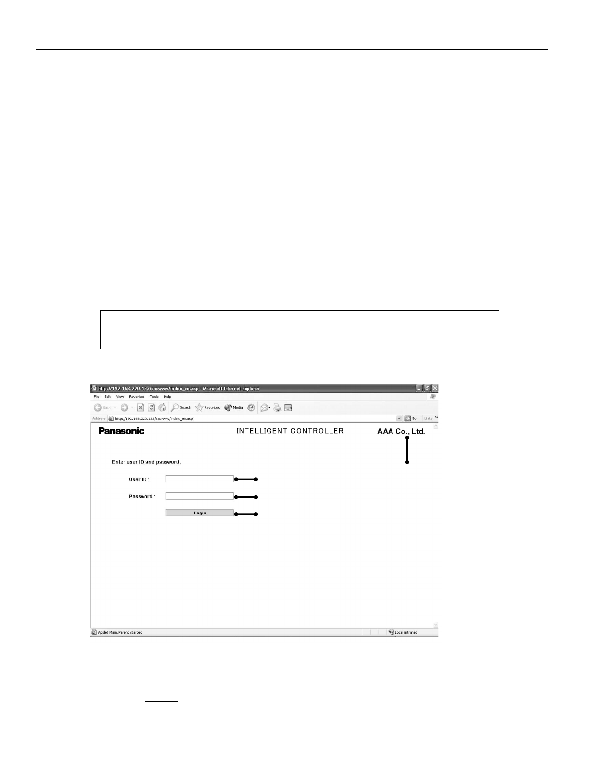
This will cause the web browser to connect to the Intelligent Controller, and a screen such as shown below appears.
Enter the user ID and password set for the Intelligent Controller to log in.
Shows the site name that was set for Intelligent Controller.
Enter the user ID that was set for Intelligent Controller.
Enter the password that was set for Intelligent Controller.
Click the Login button.
1
Page 4
SCREEN DISPLAY AND OPERATION
3. SCREEN DISPLAY AND OPERATION
3-1. [Each Tenant] Screen
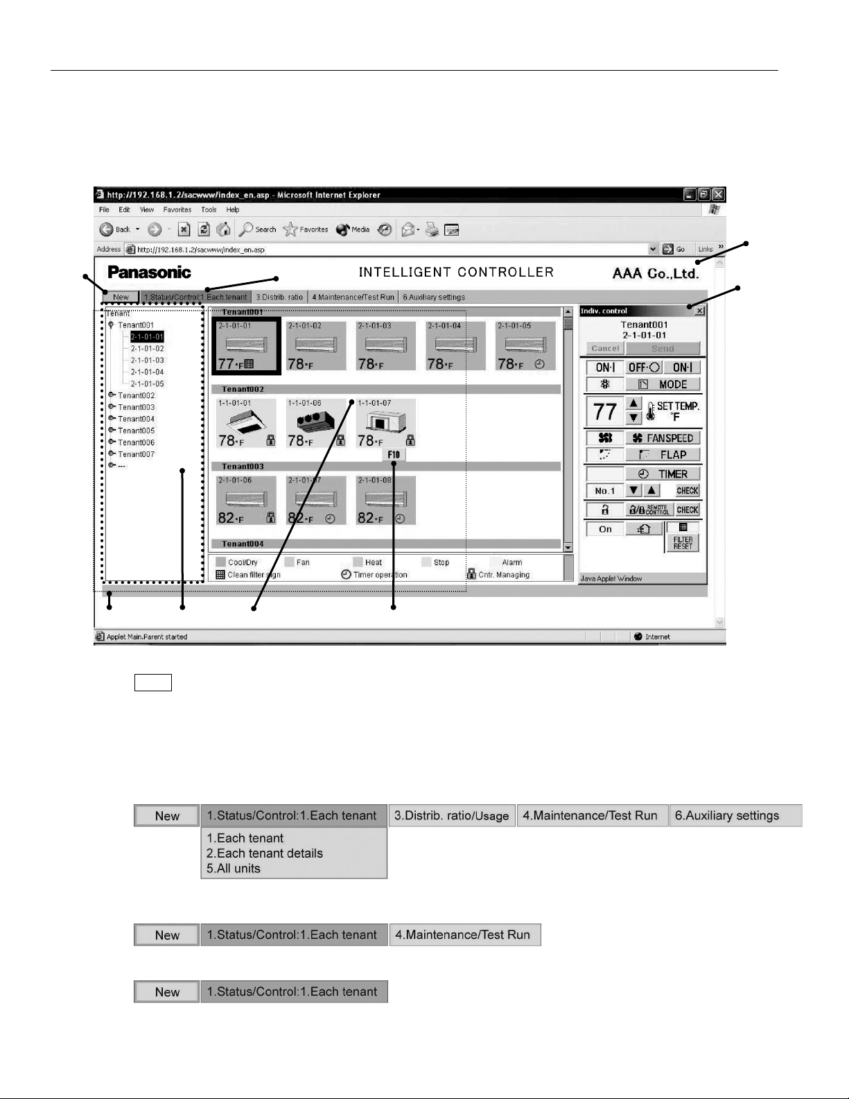
After you log in to the Intelligent Controller, or when you use the menu to select [1. Status/Control :
1. Each tenant], a screen such as shown below appears. (Screen details may differ depending on the user logged in.)
New button
Updates the screen to the latest information.
Menu
(The menu may differ depending on the user logged in. The following menu appears when logged in as an administrator.)
Lets you select one of the following screens.
★Administrator Menu
★Special User Menu
★General User Menu
2
Page 5
SCREEN DISPLAY AND OPERATION
Tenant list
Shows the indoor unit and tenant structure currently accessed by the Intelligent Controller in a list. Select indoor units by
clicking different parts of the list.
Clicking on the part highlighted in the screen example above will select the individual indoor unit, while clicking on the tenant
name (Tenant001, Tenant002, etc. in the example) will select all indoor units for that tenant. Clicking on the top of the list
(Tenant in the example) will select all indoor units of the site.
Only the tenants that can be operated by the user permission used to log in (administrator, special, general) are displayed.
Icon display area
Shows icons for indoor units connected to the Intelligent Controller.
Clicking on an icon whose frame is shown in reverse will select that unit. Clicking on a tenant name will select that tenant.
If an interface adaptor is used, the icon display becomes light purple during the ON operation.
Notification column
Shows information about the connection status of web browser and Intelligent Controller, etc.
Alarm code display
Shows the alarm code as a tooltip when the cursor is moved over the icon of the indoor unit for which the alarm is occurring.
Site name
The “Site name” set in the Intelligent Controller appears.
⑧ Remote control window
Shows the Remote control window. When this window has been closed, clicking on the indoor unit or
making another selection will bring it up again.
A
D C B
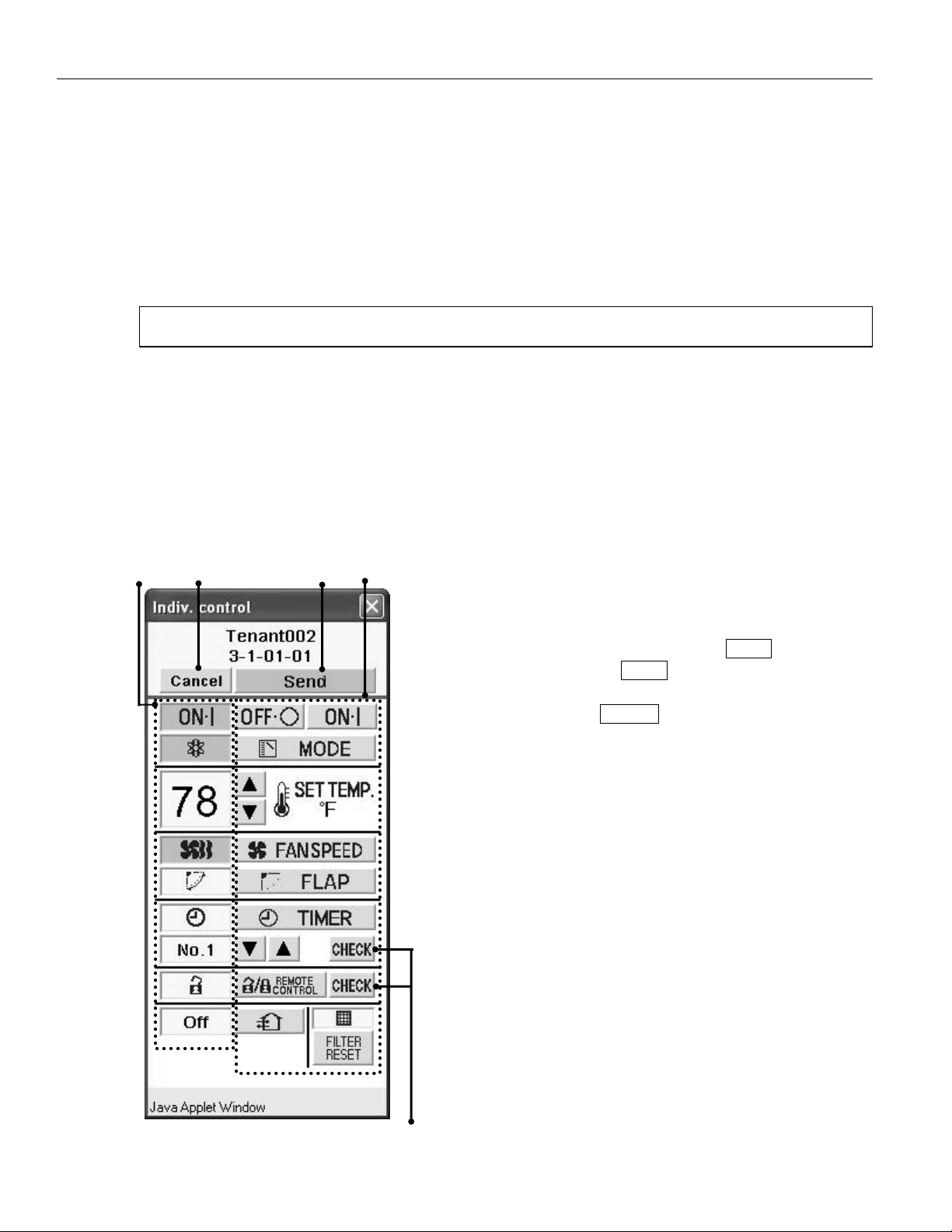
A Status/Control screen section
Shows the status of the indoor unit and the operation condition.
When a control operation is performed, the background color of
the respective field changes and the Send button becomes
available. Clicking the Send button will send all operation
steps performed up to this point to the Intelligent Controller. If
you instead click the Cancel button or perform a step such as
selecting another indoor unit, operation steps performed up to
this point will be canceled.
Remote control window
E
3
Page 6

Remote control window for general user
SCREEN DISPLAY AND OPERATION
B Control section
Shows controls for possible operation steps such as start/stop
switching, operation mode selection, temperature selection, fan
speed setting, fan direction setting etc.
If the logged in user has only general user privileges, buttons for
restricted operation steps will be grayed out (inactive).
The REMOTE CONTROL and CHECK buttons will not be
displayed.
C Send button
Sends the changes made to the
Intelligent Controller.
D Cancel button
Cancels the changes made.
E CHECK buttons
Used to check the timer setting and remote control prohibition
setting status.
(See “3-7. Program Timer Screen” and “3-9. Prohibit Remote
Control Screen”.)
Clicking the Return button will return the display to the
previous screen.
4
Page 7
SCREEN DISPLAY AND OPERATION
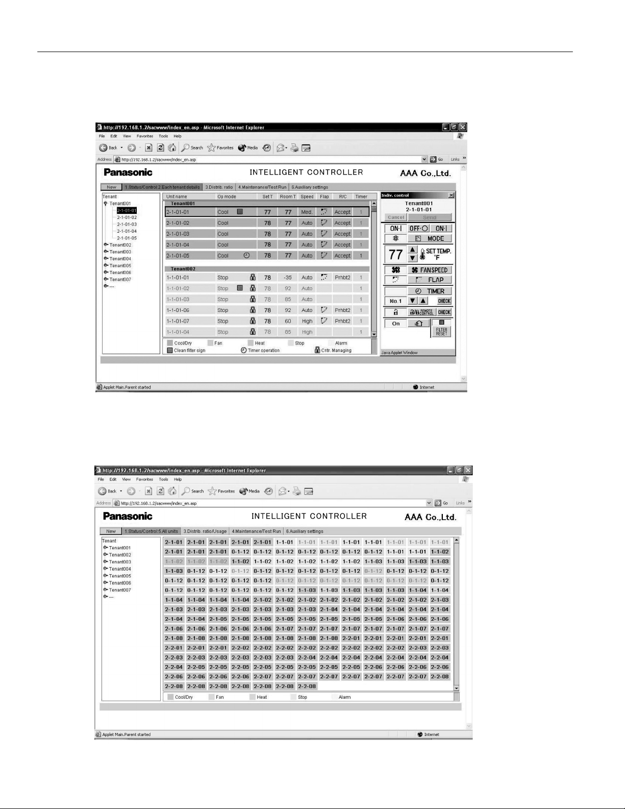
3-2. [Each Tenant Details] Screen
When you use the menu to select [1. Status/Control : 2. Each tenant details], a screen such as shown below
appears. (Screen details may differ depending on the user logged in.) Operation principles for this screen are
similar to those of the “3-1. [Each tenant] screen”.
3-3. [All Units] Screen
When you use the menu to select [1. Status/Control : 5. All units], a screen such as shown below appears.
(Screen details may differ depending on the user logged in.) A maximum of 256 indoor units are displayed in
1 screen. Operation principles for this screen are similar to those of the “3-1. [Each tenant] screen”.
5
Page 8
SCREEN DISPLAY AND OPERATION
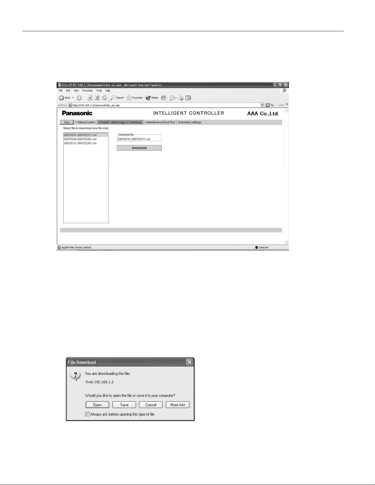
3-4. Distribution Ratio/Usage: Data Download Screen
When you use the menu to select [3. Distrib. ratio/Usage : 3. Download] while logged in as an administrator,
a screen such as shown below appears.
You can download files by selecting them and clicking the “Download” button.
A cut-off data file appears for each piece of cut-off data that appears on the Intelligent Controller unit. Be
aware, however, that the dates that appear on the Intelligent Controller unit appear as file names on this
screen.
For example, cut-off data that appears as “01/Apr-30/Apr” on the Intelligent Controller will appear as
“20070401-200704301.csv” on this screen.
When the following message appears after clicking the “Download” button, select “Open” or “Save”.
• “Open” ........ Open the selected CSV file using spreadsheet software.
• “Save” ......... Select a folder and save the CSV file.
6
Page 9

SCREEN DISPLAY AND OPERATION
3-5. Alarm Log Screen
When you use the menu to select [4. Maintenance/Test Run : 2. Alarm log] while logged in as an
administrator or special user, a screen such as shown below appears.
When an indoor unit is selected in the tree section, the previous 14 occurrences are displayed.
(Same as the display on the Intelligent Controller.)
“I/D alarm log”, “O/D comm. error log”, and “Adaptor alarm log” can be selected from the drop-down list.
7
Page 10

SCREEN DISPLAY AND OPERATION
[O/D comm. error log] logs the history of errors in communication between
the outdoor unit and the Intelligent Controller or the communication
adaptor.
[Adaptor alarm log] logs the history of warnings as determined by the Intelligent Controller or the
communication adaptor.
(Duplicate adaptor addresses, communication error between the Intelligent Controller and adaptor, etc.)
8
Page 11

SCREEN DISPLAY AND OPERATION
3-6. Mail Send Log Screen
When you use the menu to select [4. Maintenance/Test Run : 4. Sent mail log] while logged in as an
administrator, a screen such as shown below appears.
⑧
No.
The entry numbers for the sent mail log. With a maximum of 20 (No. 1 to 20) possible entries, the newest entries
appear at the top of the list. When the number of entries exceeds 20, entries are deleted starting with the oldest.
As up to three mail recipients can be specified, up to three log entries can be recorded for one alarm occurrence.
Rslt
“OK” appears when an alarm mail is sent properly, and “NG” appears when sending fails.
Send T.
The date and time the alarm mail was sent (or sending was attempted).
To
The recipient address the alarm mail was sent to. If the address is too long, only part of the address may
appear.
Unit name
The name of the indoor unit for which the alarm occurred.
Alarm code
The code for the alarm that occurred.
Stat
“Occurrence” appears when a notification of an alarm occurrence is sent, and “Restoration” appears
when a notification of an alarm restoration is sent.
Address
The address of the indoor unit for which the alarm occurred.
The address follows the format, “adaptor number - link number - system (outdoor) number - indoor number”.
When a test mail is sent, “TEST_MAIL” appears.
9
Page 12

SCREEN DISPLAY AND OPERATION
3-7. Program Timer Screen
When you use the menu to select [6. Auxiliary settings : 3. Program timer] while logged in as an
administrator, or use the “CHECK” button for timer operation in the remote control window, a screen such as
shown below appears. (As non-administrator users can only confirm settings and not configure them, the
“Cancel” and “Send” buttons only appear when logged in as an administrator.)
Tree section
“Cancel”/”Send” buttons
When the daily timer number is selected in the tree section, the current setting status is displayed.
Click the desired setting item, and you can select the setting from the drop-down list as shown below.
Drop-down lists are also displayed for the weekly timer in the same way as the daily timer number.
10
Page 13

SCREEN DISPLAY AND OPERATION
You can only configure daily timer settings one number (D1, D2, etc.) at a time. If you attempt to switch to D2
settings in the middle of configuring D1 settings, for example, the message “Send for each daily timer.”
appears.
In such a case, apply or cancel the current settings by clicking the “Send” or “Cancel” button, respectively,
before configuring the next daily timer number.
For details on the settings, refer to the operation manual for the Intelligent Controller.
The “Check RC prohib.” button appears in the previous page when logged in as an administrator or special
user. When you click on this button, a screen such as shown below appears.
11
Page 14

SCREEN DISPLAY AND OPERATION
3-8. Tenant Holiday/Timer Special Day Screen
When you use the menu to select [6. Auxiliary settings : 4. Ten.Ho/TimerSp.Day] while logged in as an
administrator, a screen such as shown below appears.
Tree section “Cancel”/”Send” buttons
“Copy” button
You can only configure tenant holiday/timer special day settings one tenant at a time. If you attempt to switch
to Tenant002 settings in the middle of configuring Tenant001 settings, for example, the message “Send for
each tenant.” appears.
In such a case, apply or cancel the current settings by clicking the “Send” or “Cancel” button, respectively,
before configuring the next tenant.
To copy changed settings, click the “Send” button and apply the settings before copying.
For details on the settings, refer to the operation manual for the Intelligent Controller.
12
Page 15

SCREEN DISPLAY AND OPERATION
3-9. Prohibit Remote Control Screen
When you use the menu to select [6. Auxiliary settings : 5. Prohibit R/C] while logged in as an administrator,
or click the “CHECK” button for prohibit remote control in the remote control window, a screen such as
shown below appears. (As non-administrator users can only confirm settings and not configure them, the
“Cancel” and “Send” buttons only appear when logged in as an administrator.)
For details on the settings, refer to the operation manual for the Intelligent Controller.
13
Page 16

SCREEN DISPLAY AND OPERATION
3-10. WEB Settings Screen
When you use the menu to select [6. Auxiliary settings” : 10. WEB settings] while logged in as an
administrator, a screen such as shown below appears.
“Cancel”/”Send” buttons
To [3.10.1. Server
details] screen
For details on the settings, refer to the operation manual for the Intelligent Controller.
Input values have the following restrictions.
Setting Item Input Range Input Character Limitations
Site name Up to 40 characters One-byte “=” is prohibited
IP address(each block)
Subnet mask
Default Gateway
DNS (Primary, Secondary)
WINS (Primary, Secondary)
Device Name
Sender's SMTP Symbols are “@” “.” “_” “:“ only
Sender's account “=“ is prohibited
Recipient account 1 to 3
Numbers 0 to 255
Numbers 0 to 255 “0.0.0.0” is prohibited
Alphanumeric characters,
“–”, and “_”
Up to 15 characters
Up to 40 alphanumeric
characters and symbols
“0.0.0.0” and “255.255.255.255” are
prohibited
First character must be alphabetic character.
“-” and “_” are prohibited as ending
characters
14
Page 17

SCREEN DISPLAY AND OPERATION
If a value that is outside the input range or input limitations is set, the window below appears.
If the network settings have been changed when the “Send” button is clicked, the window below appears.
Always check there is no problem restarting the Intelligent Controller unit.
When “YES” is clicked for submission, the screen changes as shown below, and the Intelligent Controller unit restarts.
15
Page 18

SCREEN DISPLAY AND OPERATION
When a mail test is sent, the window below appears when the mail settings have been changed.
In this case, either click the “Send” button to enable the mail setting changes or click the “Cancel” button to
disable the changes, and then send the mail test again.
If the Intelligent Controller unit is processing (check configuration, cut-off, backup, etc.), this screen cannot
be displayed or updated, mail test cannot be sent, and setting change “Send” cannot be performed.
If the Intelligent Controller unit is displaying the initial setting screen (main menu 5) or the Settings screen
(main menu 6), setting change “Send” cannot be performed. In either case, the following window appears.
3-10-1. Server details
When you click the “Server details” button from the [WEB settings] screen, a screen such as shown below appears.
To [3-10-1-1 Receiving
server settings] screen
For details on the settings, refer to the operation manual for the Intelligent Controller.
16
Page 19

Input values have the following restrictions.
Setting Item Input Range Input Character Limitations
Port number Numbers 0 to 999999
SCREEN DISPLAY AND OPERATION
User ID
Password
Up to 50 alphanumeric
characters and symbols
3-10-1-1. Receiving server settings
When you click the “Receiving server settings” button from the [Server details] screen, a screen such as
shown below appears.
For details on the settings, refer to the operation manual for the Intelligent Controller.
Input values have the following restrictions.
Setting Item Input Range Input Character Limitations
Recv. server address
(POP3)
User ID
Password
Port number Numbers 0 to 999999
Up to 40 alphanumeric characters
Symbols are “@” “.” “_” “:” only
and symbols
Up to 50 alphanumeric characters
and symbols
17
Page 20

SUPPLEMENTARY INFORMATION
4. SUPPLEMENTARY INFORMATION
■ When connecting the Intelligent Controller via Internet, consider implementing network security
measures, such as a firewall.
■ Error Messages
System configuration change!
(when logged in with Administrator
privileges)
Intelligent Controller is now
processing, please wait.
Please try later.
Error Cause Remedy
The system configuration
of the Intelligent Controller
has changed.
The Intelligent Controller
is applying settings.
Access from the Web is
heavy.
This is a warning message.
Wait a moment and resume operation.
If configuring settings with the
Intelligent Controller, switch to a
non-settings screen (such as screen
1-n).
Wait a moment and resume operation.
Communication error
Invalid user ID
Wrong password
All Stop!
All units were forced to stop.
Do not operate until unit operation
resumes.
The Intelligent Controller
was turned off while
connected, or a cable was
unplugged or the network
failure.
The entered user ID is
different from the user ID
registered on the
Intelligent Controller.
The entered password is
different from the
password registered on
the Intelligent Controller.
The external all stop input
is switched on for the
Intelligent Controller unit.
Try the operation again.
Verify that the Intelligent Controller is
turned on, and that the network wiring
connections are correct.
Verify the user ID that was registered
to the Intelligent Controller.
Verify the password that was
registered to the Intelligent Controller.
When the external all stop input is
changed to OFF, the message
disappears. After changing to OFF,
wait for the message to disappear.
18
Page 21

SUPPLEMENTARY INFORMATION
19
Page 22

SUPPLEMENTARY INFORMATION
20
Page 23

SUPPLEMENTARY INFORMATION
21
Page 24

DC1011-11111
Printed in Japan
 Loading...