

Panasonic CS-A28BKP5, CU-A28BKP5 Service Manual
Order No:
Room Air Conditioner
CS-A28BKP5/CU-A28BKP5
CONTENTS
Page Page
1 Features 2
2 Functions
3 Product Specifications
4 Dimensions
5 Refrigeration Cycle Diagram
6 Block Diagram
7 Wiring Diagram
8 Operation Details
9 Operating Instructions
10 Installation Instructions
11 3-way Valve 51
3
12 Servicing Information
6
13 Troubleshooting Guide
14 Technical Data
8
9
15 Exploded View
16 Replacemen t Parts List
10
11
17 Exploded View
12
18 Replacemen t Parts List
19 Electronic Parts List
22
42
20 Electronic Circuit Diagram
© 2002 Matsushita Air-Conditioning Corp. Sdn. Bhd.
(183914D) All rights reserved. Unauthorized copying
and distribution is a violation of law.
58
62
64
67
68
69
70
71
72

CS-A28BKP5/CU-A28BKP5
1 Features
• High Efficiency
High Efficiency Airflow Circuit
•
Compact Design
•
Auto Restart after Power Failure
•
Long Piping up to 30m
•
• Catechin Deodorizing Air Filter
Deodorizing Control during operation
•
Cold draught Control
•
2
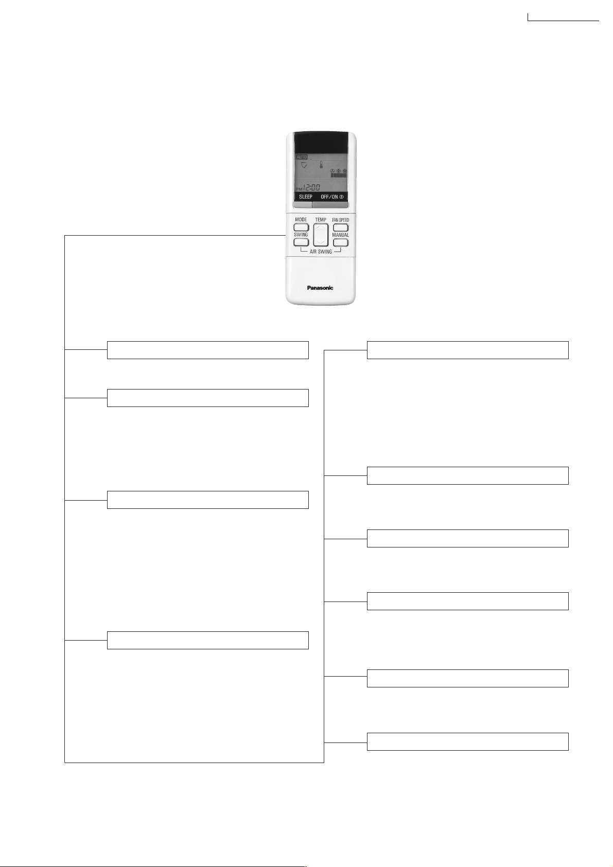
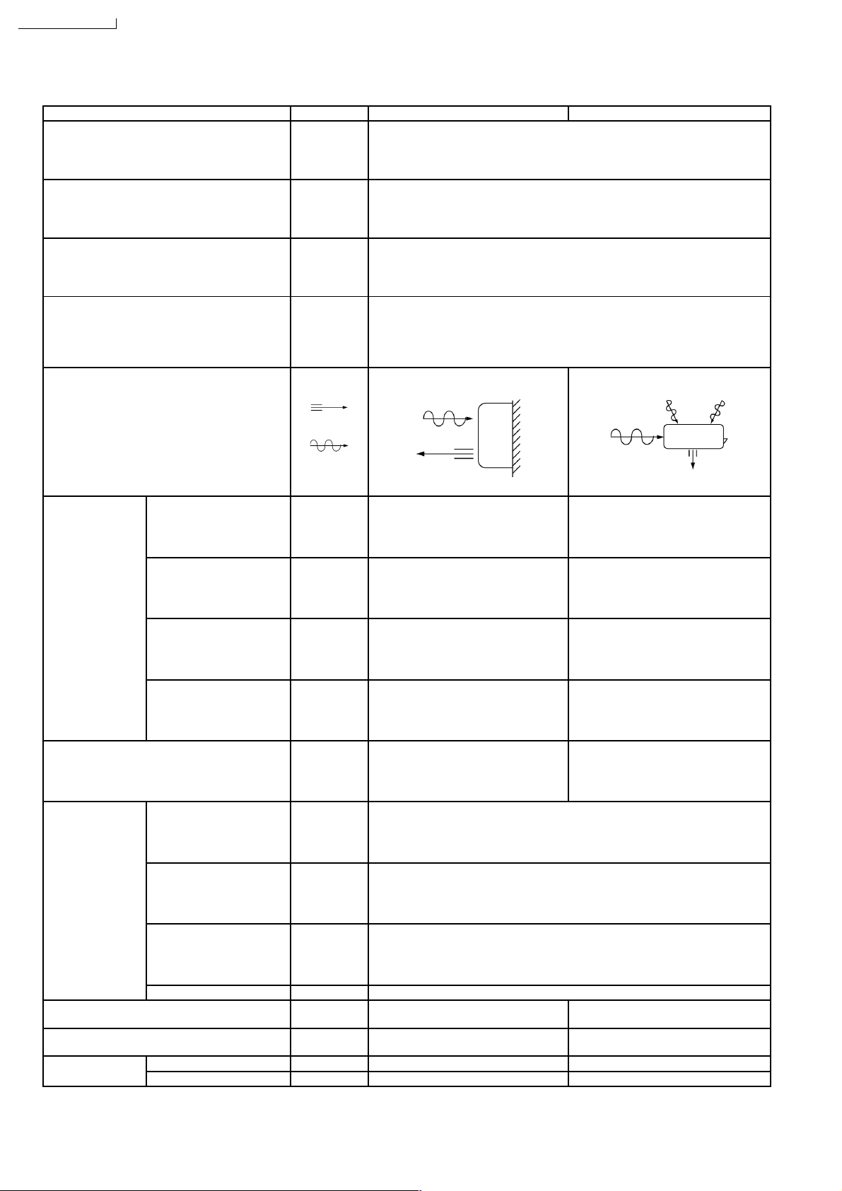
2 Functions
Remote Control
CS-A28BKP5/CU-A28BKP5
OFF / ON I
MODE
FAN SPEED
AIR SWING
Operation OFF / ON
Operation Mode Selection
•
•
•
•
AUTO
HEAT
COOL
DRY
Automatic Operation Mode
Heating Operation Mode
Cooling Operation Mode
Soft Dry Operation Mode
Indoor Fan Speed Selection
• h j k Low Speed
l
• h j k Medium Speed
lll
• h j k High Speed
lllll
•
AUTOFAN
Automatic Fan Speed
Airflow Direction Control
•
SWING
•
MANUAL
Automatic Airflow Direction
Control
Airflow Direction Manual
Control
TEMP.
ON-TIMER
OFF-TIMER
TIME
SET
CANCEL
CLOCK
(q)
Room Temperature Setting
• Temperature Setting (16˚C to 30˚C)
• Automatic Operation
m / n
n
n - o
2˚C lower than standard
Standard
2˚C higher than standard
Timer Operation Selection
• 24-hour, OFF / ON Real Timer Setting.
Time / Timer Setting
• Hours and minutes setting.
Timer Operation Set / Cancel
• ON Timer and OFF Timer setting and
cancellation.
Clock Setting
• Current time setting.
3
SLEEP
Sleep Mode Operation OFF / ON
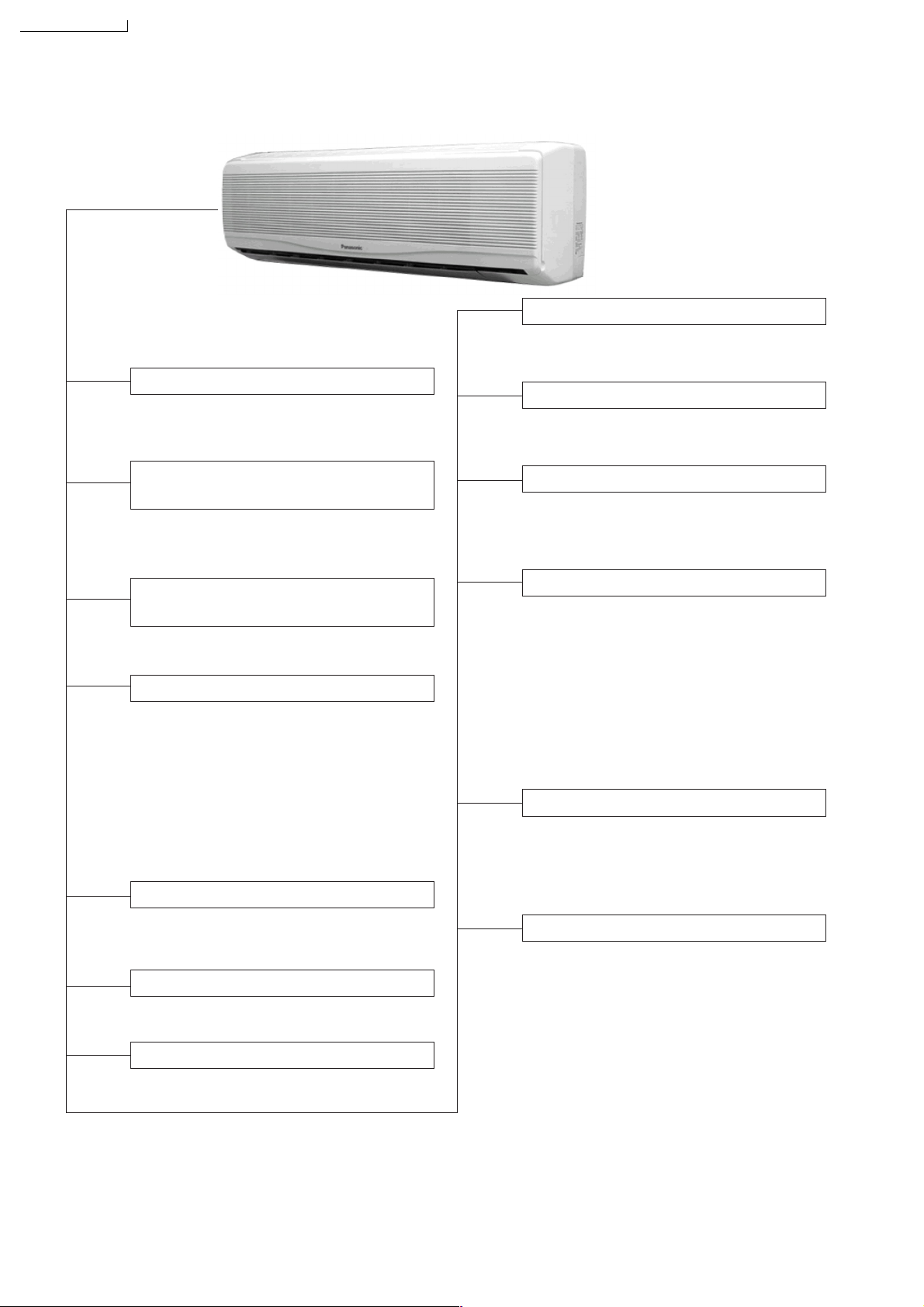
CS-A28BKP5/CU-A28BKP5
Indoor Unit
AUTO
OFF / ON
Auto Operation Switch
• Used when the remote control cannot be
used.
Auto Restart Control
• Operation is restarted after power failure
at previous setting mode.
Anti-Freezing Control
• Anti-Freezing control for indoor heat
exchanger. (Cooling and Soft Dry)
TEST RUN
OFF / ON
Remote Control Signal Receiving
Sound Control
• It can be controlled by pressing Auto
Operation Switch for 10 seconds.
Operation Test Running / Pump
Down Switch
• Used when test running or servicing.
Operation Indication Lamps (LED)
•
POWER
(Red)........ Lights up in operation,
blinks in Automatic
Operation Mode judging
and Hot Start operation.
•
SLEEP
(Orange).... Lights up in Sleep
Mode Operation.
•
TIMER
(Orange).... Lights up in Timer
Setting.
Operation Mode
• Heating, Cooling, Soft Dry, and Automatic
Mode.
Time Delay Safety Control
• Restarting is inhibited for appro. 3 minutes.
7 Minutes Time Save Control
• Cooling Operation only.
Sleep Mode Auto Control
• Indoor Fan operates at Low fan
speed.
• Operation stops after 8 hours.
Indoor Fan Speed Control
• High, Medium and Low.
• Automatic Fan Speed Mode
– Heating : Fan speed varies from Hi
➝
SLo in accordance with
indoor heat exchanger.
– Cooling : Fan rotates at Hi and Me
speed. Deodorizing control
is available.
– Soft Dry: Fan rotates at Lo speed.
Airflow Direction Control
• Automatic air swing and manual adjusted
by remote control for vertical airflow.
• Manually adjusted by hand for horizontal
airflow.
Hot-Start Control
• The indoor fan stops until the indoor heat
exchanger temperature over 30°C.
• The indoor fan operates at SLo and Lo
when indoor heat exchanger temperature
reaches 30°C ~ 42°C.
• Hot start is completed when indoor heat
exchanger reaches 42°C.
4
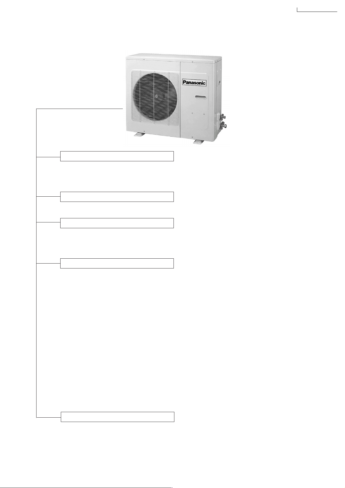
Outdoor Unit
4-Way Valve Control
• When the unit is switched to “OFF”
during Heating operation, 4-way valve
stays at Heating Position for 5 minutes.
CS-A28BKP5/CU-A28BKP5
Overload Protector
• Inner protector (Compressor, Fan Motor).
60 Secs. Forced Operation Control
• Once the compressor is activated, it
does not stop for 60 secs. (Stops immediately with remote control stop signal.)
Outdoor Fan Operation Control
•
4-pole induction motor (2-speed)
• For Cooling or Soft Dry Operation
Hi-speed … when outdoor temperature
reaches to 31°C
Lo-speed … when outdoor temperature
reaches to 29°C
• For Heating Operation
Hi-speed ... when outdoor temperature
reaches to 13.5°C.
Lo-speed ... when outdoor temperature
reaches to 15.5°C.
• For Over-heating Protection, the Fan is
switched ON or OFF depending on the
piping temperature and the outdoor
temperature.
Deice Control
•
To prevent frosting at outdoor heat
exchanger during Heating Operation.
5
CS-A28BKP5/CU-A28BKP5
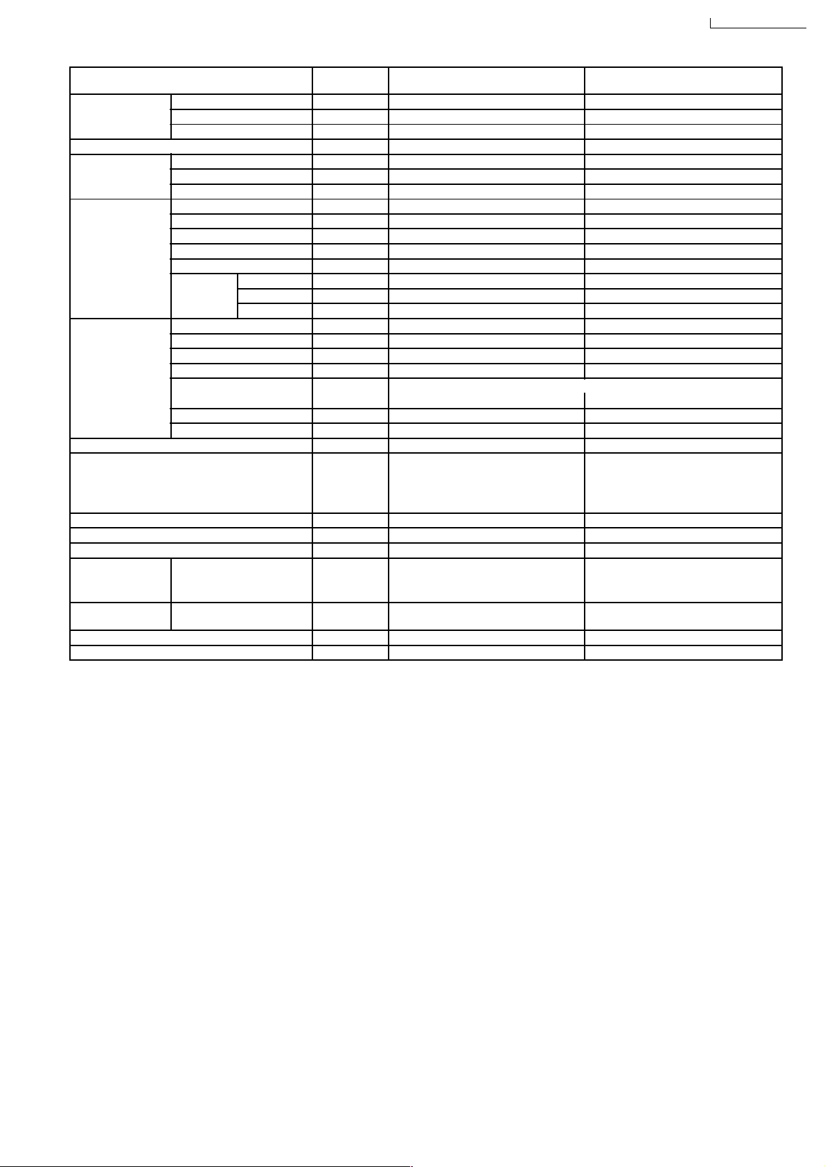
3 Product Specifications
Unit CS-A28BKP5 CU-A28BKP5
Cooling Capacity kW
Heating Capacity kW
Moisture Removal l/h
Power Source Phase
Airflow Method OUTLET
Air Volume Indoor Air (Lo) m3/min (cfm) Cooling; 14.2 (501) —
Btu/h
Btu/h
Pint/h
V
Cycle
SIDE VIEW TOP VIEW
INTAKE
Heating; 15.6 (551)
7.92 - 7.80
27,000 - 26,600
8.35 - 8.25
28,500 - 28,200
4.6
9.7
Single
230 - 220
50
Indoor Air (Me) m3/min (cfm) Cooling; 15.0 (530) —
Heating; 16.4 (579)
Indoor Air (Hi) m3/min (cfm) Cooling; 16.3 (575) —
Heating; 17.7 (625)
Outdoor Air m3/min (cfm) — Cooling; 59.0 (2,083)
Heating; 59.2 (2,090)
Noise Level dB (A) Cooling; 48/46/44 Cooling; 63/55
Heating; 48/44 Heating; 63/55
Electrical Data Input kW Cooling; 2.62 -2.60
Heating; 2.88 - 2.85
Running Current A Cooling; 12.2 - 12.5
Heating; 13.2 - 13..5
COP W/W Cooling; 3.0 - 3.0
Heating; 2.9 - 2.9
Starting Current A 76
Piping Connection Port
(Flare piping)
Pipe Size
(Flare piping)
Drain
Hose
Inner diameter mm 14 —
Length m 0.73 —
inch
inch
inch
inch
G ; Half Union 5/8”
L ; Half Union 1/4”
G (gas side); 5/8”
L (liquid side); 1/4”
6
G ; 3-way valve 5/8”
L ; 3-way valve 1/4”
G (gas side); 5/8”
L (liquid side); 1/4”
CS-A28BKP5/CU-A28BKP5
Power Cord Length
Number of core-wire
m 2.1
3 (2.5 mm
2
)
—
—
Dimensions Height inch (mm) 14 - 9/16 (370) 26 - 31/32 (685)
Width inch (mm) 48 - 1/32 (1,220) 34 - 21/32 (880)
Depth inch (mm) 8 - 21/32 (220) 13 - 19/32 (345)
Net Weight lb (kg) 40 (18) 150 (68)
Compressor Type — Scroll type
Motor Type — Induction (2-poles)
Rated Output kW — 2.11
Air Circulation Type Cross-flow Fan Propeller Fan
Material AS + Glass Fiber 30% AS + Glass Fiber 20%
Motor Type Induction (4-poles) Induction (4-poles)
Input W — —
Rated Output W 40 100
Fan Speed Low rpm Cooling; 1,262 Heating; 1,250 920 - 880
Medium rpm Cooling; 1,322 Heating; 1,328 —
High rpm Cooling; 1,418 Heating; 1,420 1,200 - 1,170
Heat Exchanger Description Evaporator Condenser
Tube material Copper Copper
Fin material Aluminium Aluminium
Fin Type Louver Louver
Row / Stage (Plate fin configuration, forced draft)
2×10 2×26
FPI 18 18
Size (W × H × L) mm 966.5 × 254 × 44 826 × 663.9 × 44
Refrigerant Control Device — Capillary Tube
Refrigeration Oil (cm3) — SONTEX
200 LT (1,242)
Refrigerant (R-22) g (oz) — 1,800 (63.5)
Thermostat Electronic Control Electronic Control
Protection Device Inner Protector Inner Protector
Capillary Tube Length mm — Cooling; 850, Heating; 1,200
Flow Rate l/min — Cooling; 21.8, Heating; 23 (1/2 ATM)
Inner Diameter mm — Cooling; 2.0, Heating; 2.4
Air Filter Material
Style
A.B.S
Honeycomb
—
Compressor Capacitor µF, VAC — 50 µF, 370VAC
Fan Motor Capacitor µF, VAC 2.0 µF, 450VAC 3.0 µF, 450VAC
•
Specifications are subject to change without notice for further improvement.
7
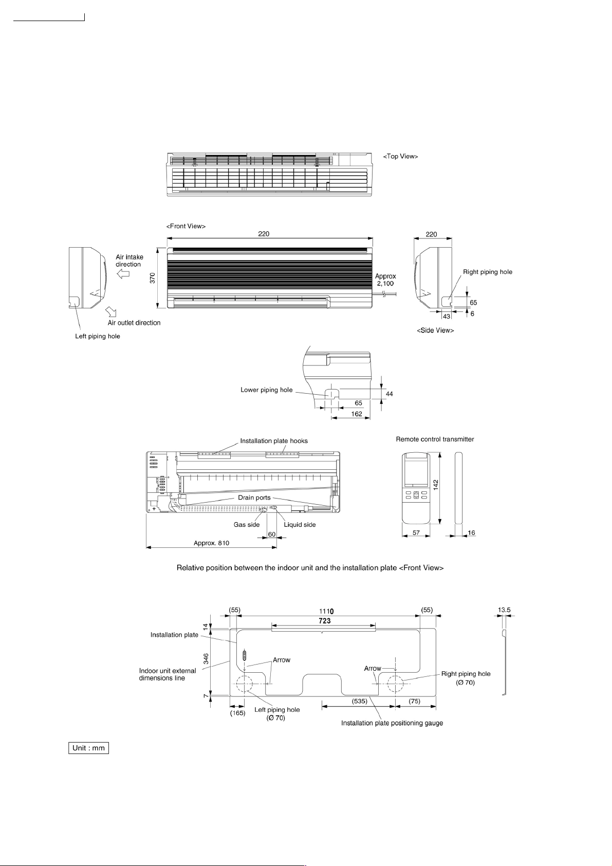
CS-A28BKP5/CU-A28BKP5
4 Dimensions
CS-A28BKP5/ CU-A28BKP5
8
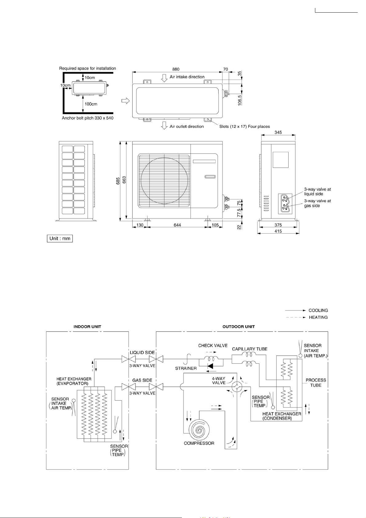
Dimensions
CS-A28BKP5/CU-A28BKP5
CS-A28BKP5/CU-A28BKP5
5 Refrigeration Cycle Diagram
CS-A28BKP5/CU-A28BKP5
CS-A28BKP5/CU-A28BKP5
9
CS-A28BKP5/CU-A28BKP5
6 Block Diagram
CS-A28BKP5/CU-A28BKP5
10
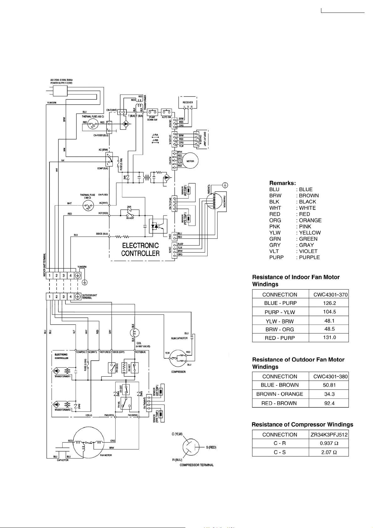
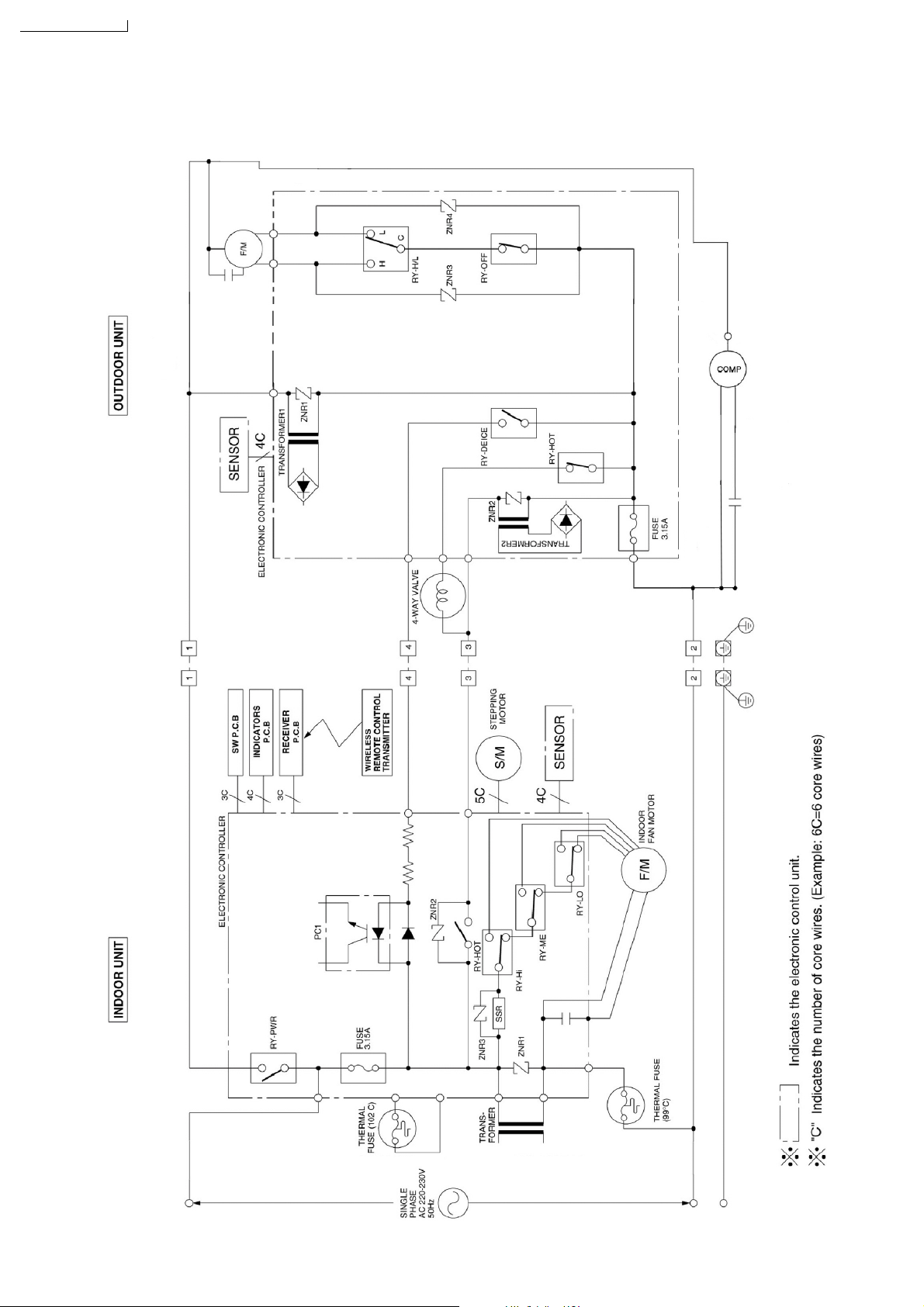
7 Wiring Diagram
CS-A28BKP5 / CU-A28BKP5
CS-A28BKP5/CU-A28BKP5
11
CS-A28BKP5/CU-A28BKP5
8 Operation Details
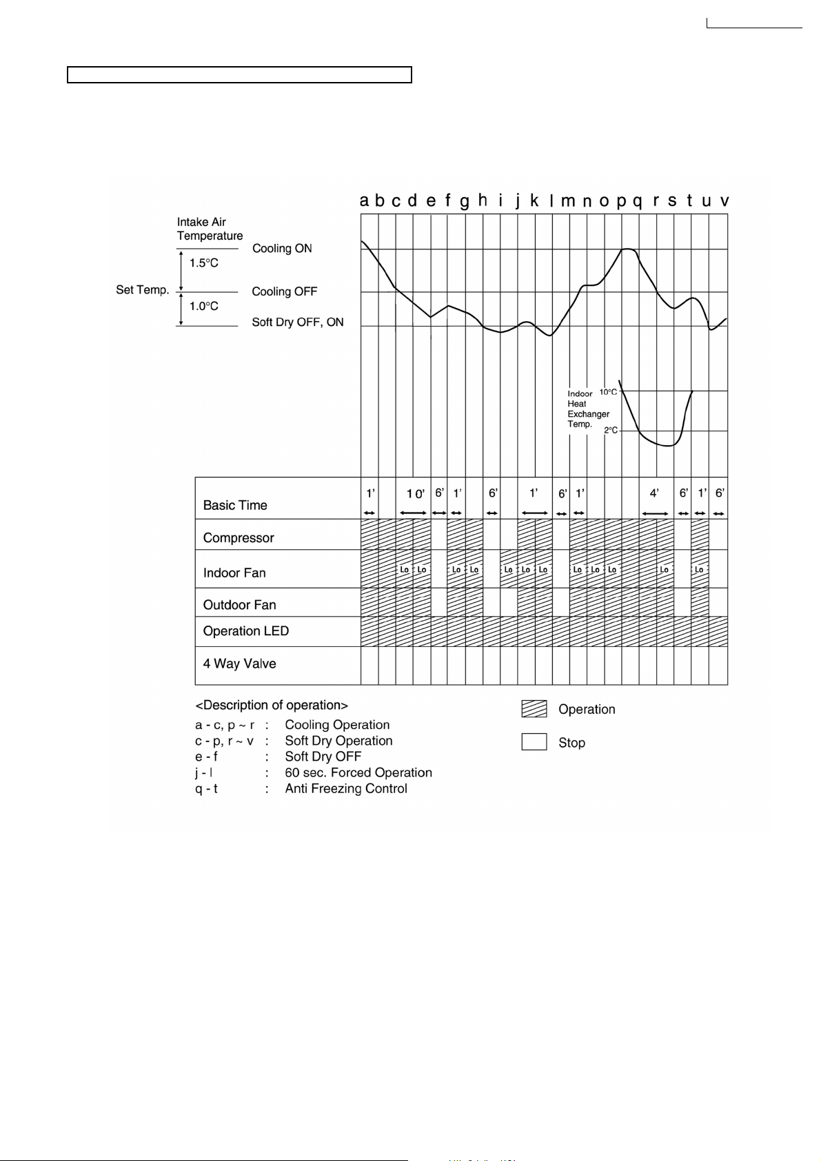
8.1. Cooling Mode Operation
Cooling in operation according to Remote Control setting.
Time Delay Safety Control (3 minutes)
When the compressor is stopped by Power Switch, Remote Control or there is a power failure, it restarts after 3 minutes when
•
the Power Switch, Remote Control is turned ON or the power supply is resumed.
When the setting temperature is reached during cooling operation, the compressor stops and it will not start for 3 minutes.
•
7 minutes Time Saved Control
The compressor will start automatically if it has stopped for 7 minutes even if the room temperature is below the compressor
•
ON temperature.
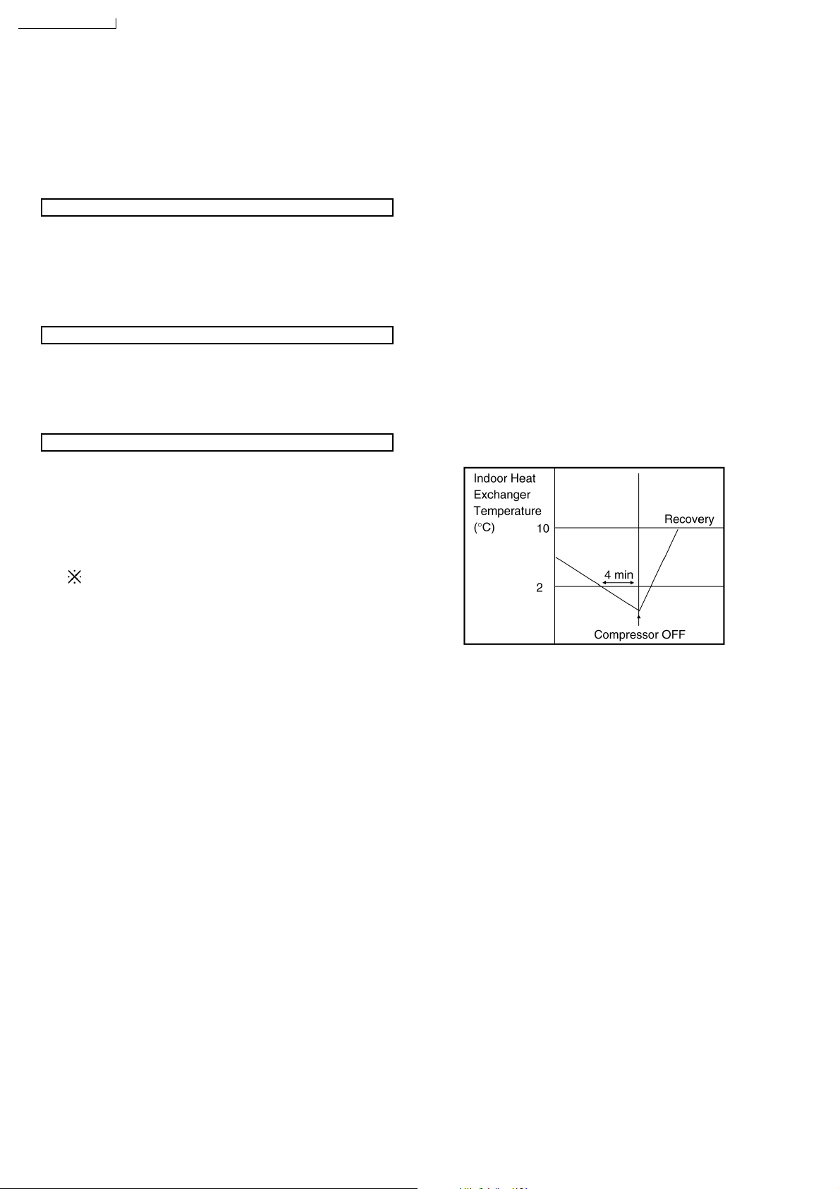
Anti-Freezing Control
If the temperature of the indoor heat exchanger falls
•
continuously below 2°C for 4 minutes, the compressor turns
off to protect the indoor heat exchanger from freezing. The
fan speed setting remains the same.
Compressor recommences when the indoor heat
•
exchanger temperature rises to 10°C (Recovery).
3 minutes waiting of Time Delay Safety Control is
valid for Cooling Operation.
12
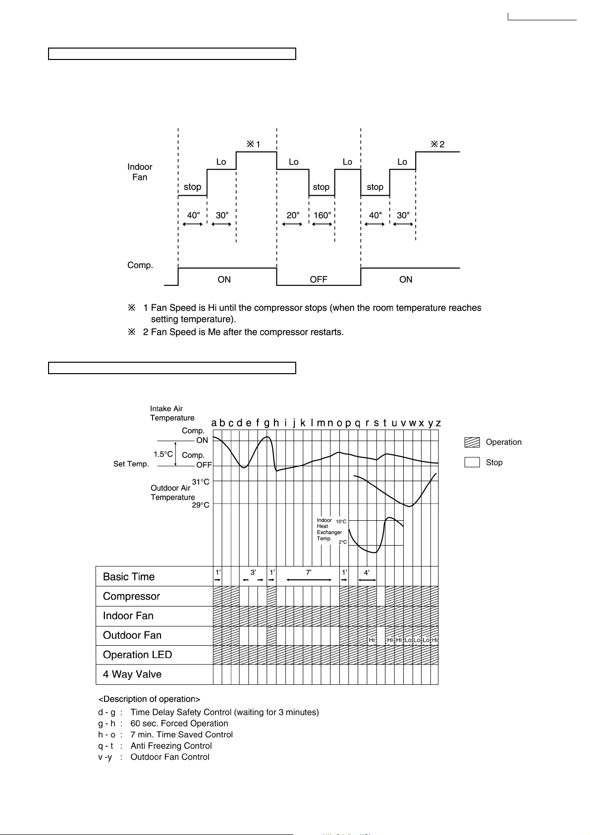
Automatic Fan Speed Mode
When Automatic Fan Speed is selected at Remote Control during cooling operation.
Fan speed rotates in the range of Hi to Me.
•
Deodorizing Control.
•
CS-A28BKP5/CU-A28BKP5
Cooling Operation Time Diagram
13
CS-A28BKP5/CU-A28BKP5
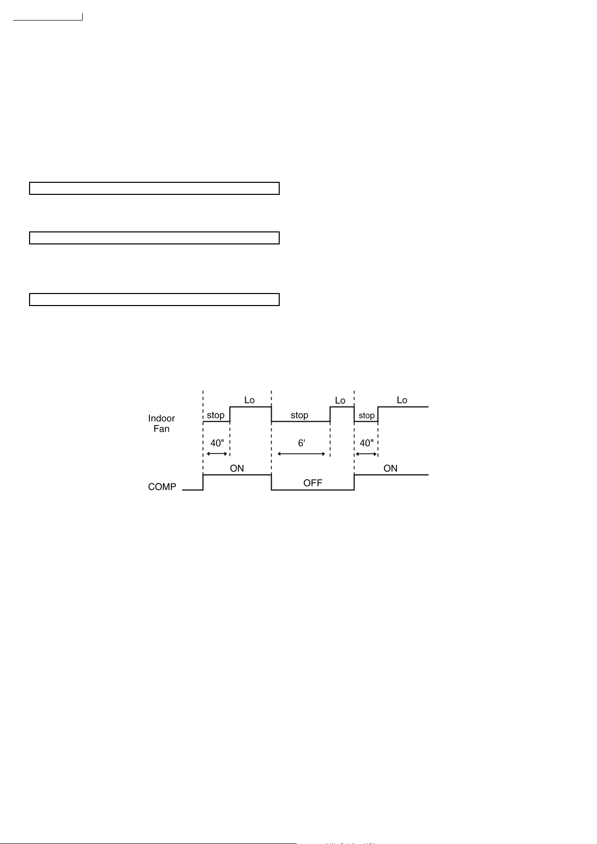
8.2. Soft Dry Mode Operation
The unit starts cooling operation until the room temperature reaches the setting temperature set on the Remote Control, and
•
then Soft Dry operation will start.
During Soft Dry operation, the Indoor Fan operates with Lo speed.
•
Once room temperature reaches below Soft Dry OFF temperature, Indoor Fan, Compressor and Outdoor Fan Stop for 6
•
minutes.
Time Delay Safety Control
Once the compressor stops, it will not start for 3 minutes during Cooling operation.
•
Anti-Freezing Control
Same as Anti-Freezing Control for Cooling Mode operation. (For Soft Dry region, 6 minutes waiting is valid during compressor
•
stops.)
Automatic Fan Speed Mode
When Automatic Fan Speed is selected at Remote Control during Soft Dry operation.
Fan speed rotates at Lo speed.
•
Deodorizing Control.
•
14
Soft Dry Operation Time Diagram
CS-A28BKP5/CU-A28BKP5
15
CS-A28BKP5/CU-A28BKP5
8.3. Heating Mode Operation
Heating in operation according to Remote Control setting.
•
Time Delay Safety Control
When the compressor is stopped by Power Switch, Remote Control or there is a power failure, it restarts after 3 minutes when
•
the Power Switch, Remote Control is turned ON or the power supply is resumed.
When the setting temperature is reached during heating operation, the compressor stops and it will not start for 4 minutes.
•
30 minutes Time Saved Control
The compressor will start automatically if it has stopped for 30 minutes even if the room temperature is below the compre ssor
•
OFF temperature.
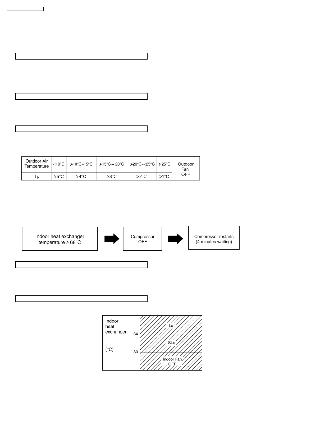
Overload Protection Control
If the temperature of the Outdoor Heat Exchanger less than -3°C, Outdoor Fan is ON. The Outdoor Fan stop, when Outdoor
•
Heat Exchanger temperature is T
or more according to Outdoor Air Temperature region as table below:
b
During starting of Heating mode and after deice, Outdoor Fan ON for 90 sec. (Hi).
If the Indoor heat exchanger becomes 68°C or more, the compressor will stop and restart automatically.
•
(Time Delay Safety Control - 4 minutes waiting)
4-way Valve Control
4-way valve ON during Heating operation, except deicing operation.
•
When the unit is switched to “OFF” during Heating operation, 4-way valve stay at Heating position for 5 minutes.
•
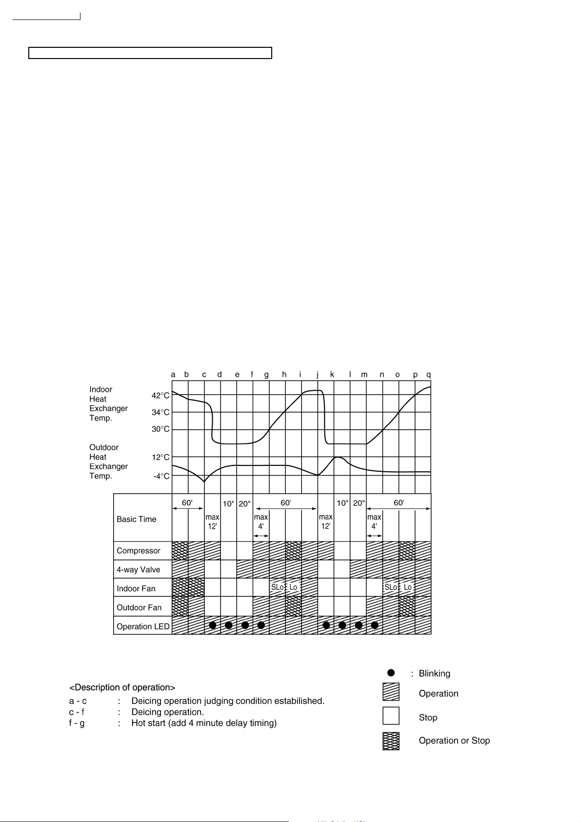
Hot Start Control
When Heating operation starts, Indoor Fan will not start until the indoor heat exchanger reaches 30°C as diagram shown.
Hot Start is completed when indoor heat exchanger reaches
42°C.
Maximum Hot start duration = 4 minutes. After 4 minutes, Hot
start operation will be shifted to normal Heating operation.
16
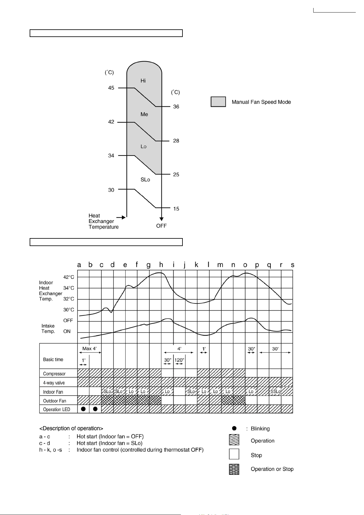
Automatic Fan Speed Mode
When Automatic Fan Speed is selected at Remote Control during heating operation.
Fan speed rotates in the range of Hi→SLo according to the heat exchanger temperature.
•
CS-A28BKP5/CU-A28BKP5
Heating Operating Time Diagram
17
CS-A28BKP5/CU-A28BKP5
Deicing Control
Deice starts to prevent frosting at outdoor heat exchanger.
Normal Deicing
•
Deice operations detection commences in Heating operation starts or 60 minutes after previous deice operation. If the
outdoor piping temperature drops to -4°C for 50 sec. continuously during compressor is in operation, deice will start.
(There is no detection during Outdoor Fan stops.)
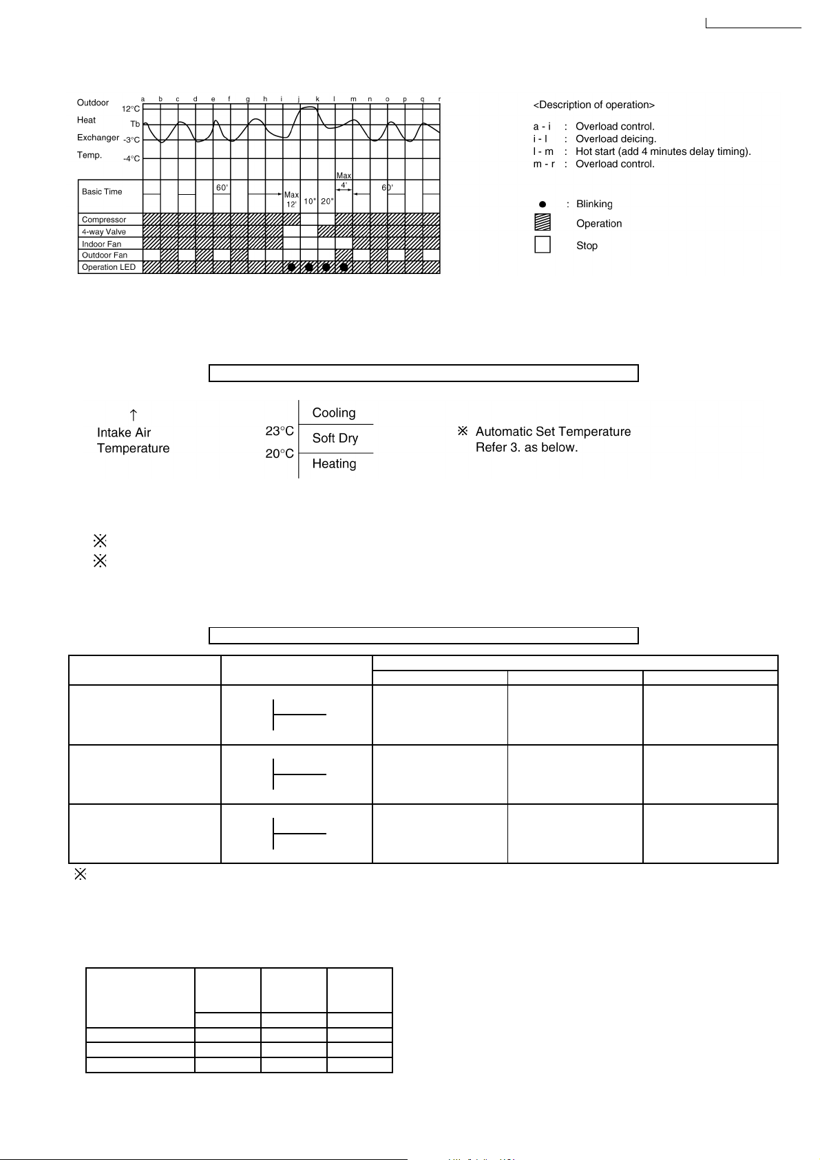
Overload Deicing
•
During heating operation, if the outdoor Fan OFF duration (due to overload control) is accumulated up to 60 minutes and
after compressor starts for 1 minute, deicing starts.
Deicing ends when
•
(a) 12 minutes after deicing operation starts;
(b) The outdoor piping temperature rises to about 12°C.
After deicing operation, compressor stops for 30 seconds and 4-way valve stays at cooling position for 10 seconds.
•
a) Normal Deicing Time Diagram
18
CS-A28BKP5/CU-A28BKP5
b) Overload Deicing Time Diagram
8.4. Automatic Mode Operation
1. When the Automatic Mode Operation is selected, the indoor fan operates at SLo fan speed for 20 seconds to sense intake air
temperature and determine the 1st operation mode.
Standard for Determining Operation Mode 1st Judgement
2. Operation mode will be determine again after 1 hour of operation, if the room temperature reaches to set temperature and
compressor off time is over 7 minutes 30 seconds continuously.
Indoor intake air is less than 16°C, Heating mode will immediate operate. (only in the first time judgement)
The present operation mode will be continued, if the room temperature does not reach to set temperature (Compressor
keeps running) eventhough after 1 hour from automatic operation mode started.
For 2nd judgement onwards, indoor fan will operate for 20 seconds to sense the intake air temperature for determining
operation mode.
Standard for Determining Operation Mode 2nd Judgement onwards
Present Judgement Next Mode
Mode Cooling Soft Dry Heating
O O
Cooling 23°C Cooling (Judgement: Not Applicable (Judgement:
Heating 23°C & Above) Below 23°C)
O O
Soft Dry 20°C Soft Dry Not Applicable (Judgement: (Judgement:
Heating 20°C & Above) Below 20°C)
O O
Heating Cooling (Judgement: Not Applicable (Judgement:
25°C Heating 25°C & Above) Below 25°C)
Automatic Set Temperature Refer 3. as below.
3. Automatic Set Temperature
For each operation, set temperature will automatically set as shown below.
However it can be selected 2°C higher or 2°C lower from standard set temperature by pressing the “Room Temperature Setting
button”.
Operation Higher Standard Lower
Mode
(+2°C) (±0°C) (-2°C)
Cooling 27°C 25°C 23°C
Soft Dry 24°C 22°C 20°C
Heating 23°C 21°C 19°C
19
CS-A28BKP5/CU-A28BKP5
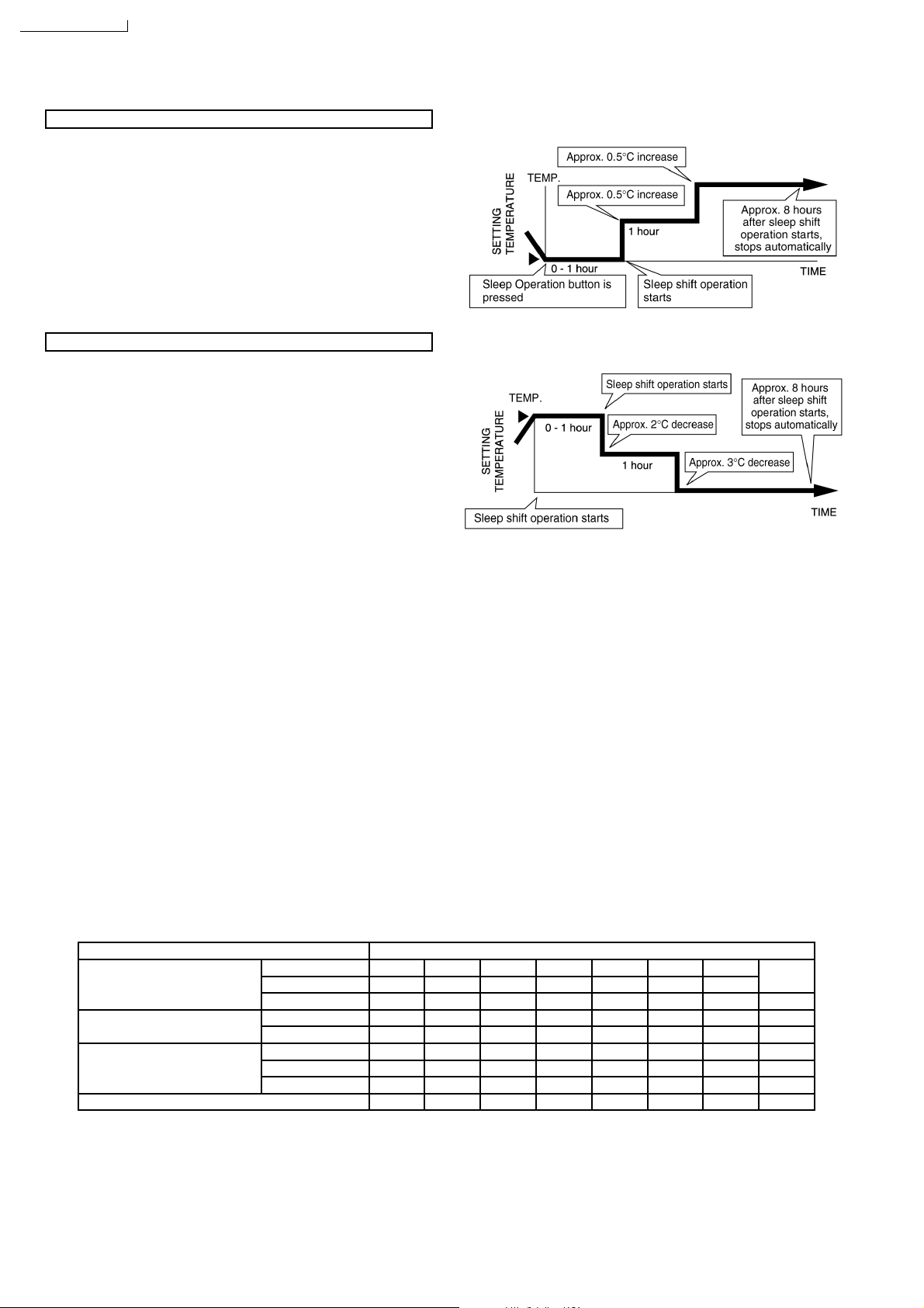
8.5. Sleep Mode Auto Operation
Cooling or Soft Dry Operation
When you press the SLEEP Mode, the following movement will
start to avoid overcooling.
The fan speed refer to Indoor Fan Motor Control.
•
The setting temperature will be risen by
•
operation and by
The operation will stop after8hours.
•
When using together with the Timer, the ON-Timer has
•
0.5
°C one hour later.
priority.
Heating Operation
When you press the SLEEP Mode, the following movement will
start to avoid overheating.
The fan speed refer to Indoor Fan Motor Control.
•
The setting temperature will be descented by 2°C at the start
•
of operation and by 3°C one hour later.
The operation will stop after8hours.
•
When using together with the Timer, the ON-Timer has
•
priority.
0.5
°C at the start of
8.6. Auto Restart Control
If there is a power failure, operation will be automatically restarted when the power is resumed.
•
It will start with previous operation mode and airflow direction.
(Time Delay Safety Control is valid)
Auto Restart Control is not available when Timer or Sleep Mode is set.
•
This control can be omitted by cutting the jumper wire J2. (Refer Circuit Diagram)
•
8.7. Indoor Fan Speed Control
Auto Fan Speed Control
•
When set to Auto Fan Speed, the fan speed is adjusted between maximum and minimum setting as shown in the table.
Manual Fan Speed Control
•
Basic fan speed adjustment (3 settings, from Lo to Hi) can be carried out by using the Fan Speed selection button.
Fan Speed High Speed
Manual O O O
Cooling Auto O O O O
Sleep O
Soft Dry Manual, Auto O
Sleep O
Manual O O O
Heating Auto O O O O O O
Sleep O O O
Hi Me Lo SLo SSLo STOP
O
←→
Low Speed
20
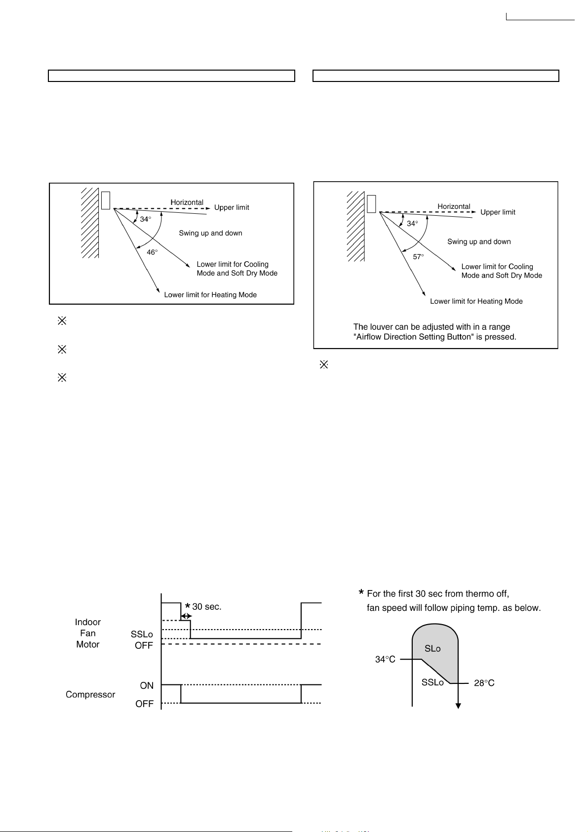
8.8. Airflow Direction Control
CS-A28BKP5/CU-A28BKP5
Airflow Direction Auto-Control
When set a Airflow Direction Auto-Control with remote
•
control, the louver swings up and down as shown in the
diagram.
The louver does not swing when the Indoor Fan stops
•
during operation.
When stopped with remote control, the discharge vent is
•
closed with the louver.
The left and right airflow direction louvers can be adjusted
manually.
1 There is no swinging while indoor fan is stopped during
Cooling and Soft Dry operation.
2 In Heating operation, when the indoor heat exchanger
temperature rises to 38°C, the airflow direction is changed
from upper limit to lower limit. When the indoor heat
exchanger temperature falls to 35°C, the air flow direction
is changed from lower limit to upper limit.
Airflow Direction Manual Control
When the airflow direction set button is pressed, the
•
automatic airflow is released and the airflow direction louver
move up and down in the range shown in the diagram.
The louver can be stopped by releasing the button at the
desired louver position.
When the remote control is used to stop the operation, the
•
discharge vent is closed with airflow direction louver.
The left and right airflow direction louvers can be adjusted
manually.
8.9. Delay ON Timer Control
When the Delayed ON Timer is set by using the remote control, the unit will start operate slightly before the set time, so that
•
the room will reach nearly to the set temperature by the desired time.
For Cooling and Soft Dry mode, the operation will start 15 minutes before the set time.
•
For Heating mode, the operation will start 30 minutes before the set time.
•
For Automatic mode, the indoor fan will operate at SLo speed for 20 seconds, 30 minutes before the set time to detect the
•
intake air temperature to determine the operation mode. The operation indication lamp will blink at this time.
8.10. Cold Draught Control
When COMP = Thermal OFF, indoor fan speed immediately changed to SLo for 30 sec., followed by SSLo speed until COMP
•
= ON.
During cold draft c/m operation, fan speed will be SSLo only.
SSLo: Fan will be running at Lo speed with SSR ON for 0.6 sec. and OFF for 5.0 sec.
21
CS-A28BKP5/CU-A28BKP5
9 Operating Instructions
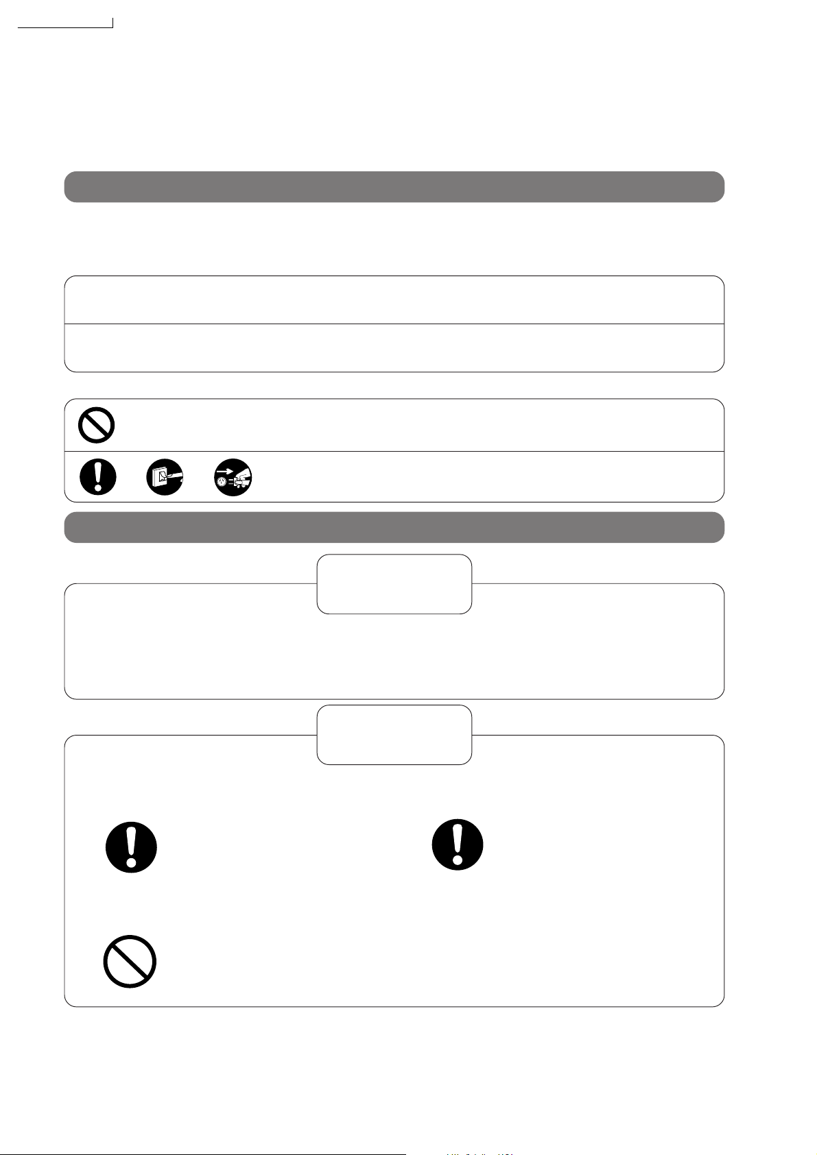
Safety Precautions
Before operating, please read the following “Safety Precautions” carefully.
To prevent personal injury, injury to others and property damage, the following instructions must be followed.
■ Incorrect operation due to ignoring of instructions will cause harm or damage, the seriousness of which is
classified as follows :
Warning
:
This sign warns of death or serious injury.
!
!
■ The instructions to be followed are classified by the following symbols :
Caution
OFF
This sign warns of injury or damage to property only.
:
This symbol (with a white background) denotes an action that is
PROHIBITED.
These symbols (with a black background) denote an action that is
COMPULSORY.
Installation precautions
Warning
!
■ Do not install, remove and reinstall the unit yourself.
Improper installation will cause leakage, electric shock or fire. Please consult an authorized dealer or
specialist for the installation work.
!
■ This room air conditioner must be
earthed.
Improper grounding could cause
electric shock.
■ Do not install the unit in a place where
there may be explosive gas leaks.
Gas leaks near the unit could
cause fires.
Caution
■ Ensure that drainage piping is connected
properly.
Otherwise, water will leak out.
22
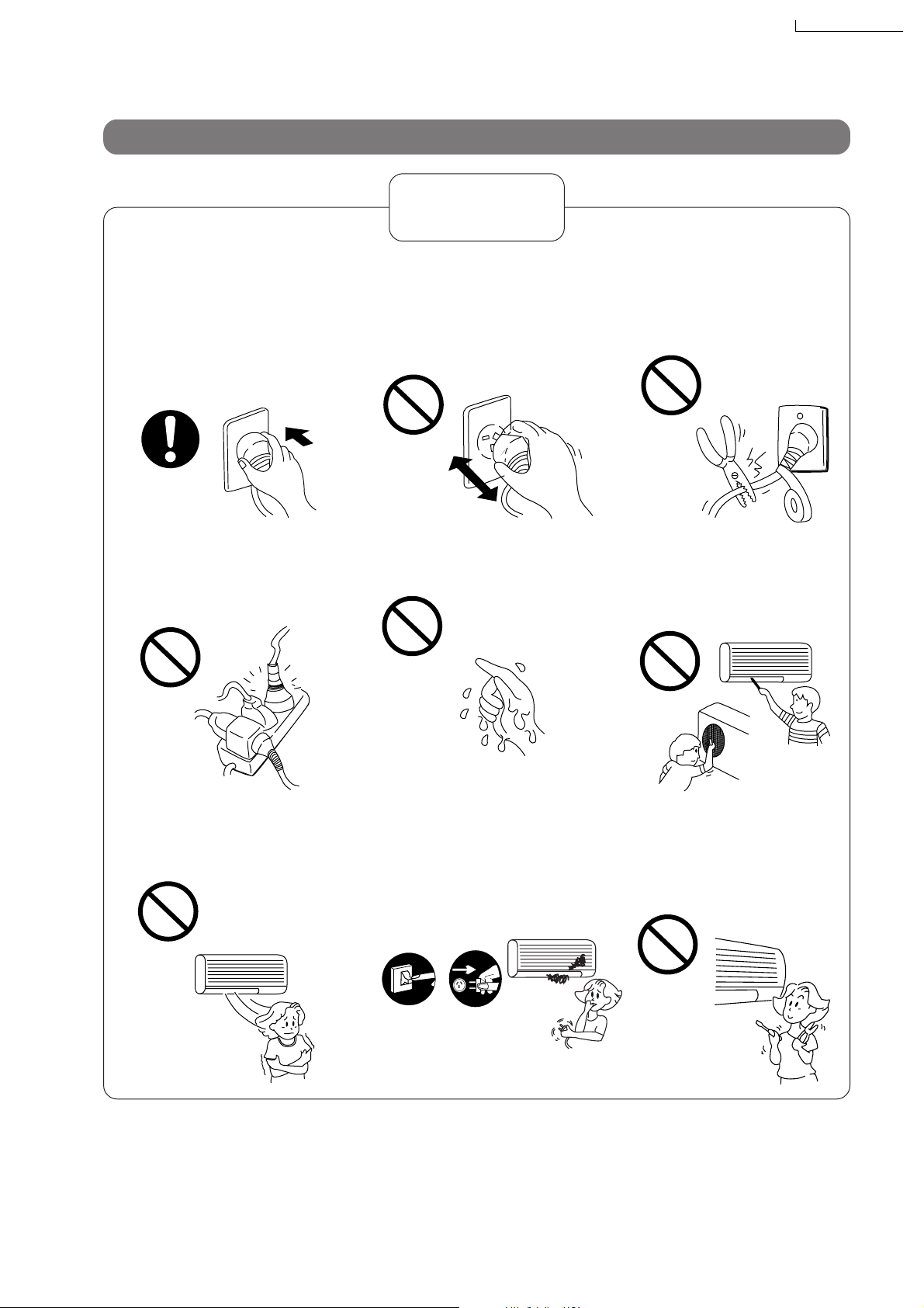
Operation precautions
Warning
!
CS-A28BKP5/CU-A28BKP5
■ Insert the power plug
properly.
Heat generated by a loose
power plug could cause electric
shock or fire.
Electrical outlet and power plug
shall be easily accessible.
■ Do not modify the length of
the power cord or use an
extension cord.
It could cause electric shock or
fire.
■ Do not operate or stop the
unit by inserting or pulling
out the power plug.
It could cause electric shock or
fire.
■ Do not operate the unit with
wet hands.
It could cause an electric shock.
■ Do not damage or use an
unspecified power cord.
It will cause electrical shock or
fire.
■ Do not insert finger, sticks
or other objects into the
units.
It could lead to physical injury
and cause damage to the units.
■ Do not be directly exposed
to the cold airstream for
too long.
It could lead to health problems.
■
If there is a smell of burning,
stop the air conditioner and
disconnect the power supply.
The heat generated could cause
electric shock or fire. Please consult an authorized dealer or service centre.
F
F
O
Switch off
the breaker.
Disconnect
the power
plug.
23
■ Do not try to repair the unit
yourself.
It could lead to fire or cause an
electric shock. Please call an
authorized dealer or service
centre.
CS-A28BKP5/CU-A28BKP5
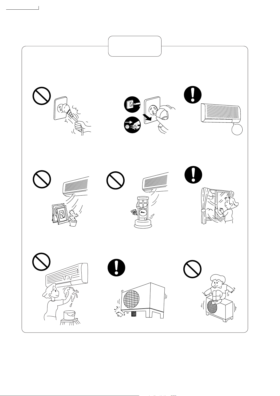
Caution
!
■ Do not remove the power
plug by pulling the cord.
Hold the plug when disconnecting the plug from the wall outlet.
■ Do not use for other pur-
poses.
Do not use for preservation purposes. It will affect food quality,
animals or plants.
■
Switch off the power supply if
the unit is not going to be
used for a long period of time.
If dust accumulates on the plug, it
will generate heat and this could
cause a fire.
Switch off
the breaker.
Disconnect
the power
plug.
OFF
■ Do not place combustor in
the path of the airflow from
the unit.
Incomplete combustion could
cause toxic gas (CO) poisoning.
■ When cleaning the unit, re-
move the plug.
This is to prevent injury due to
the rotating fan in the unit.
OFF
■
Ventilate the room regularly.
If not ventilated regularly, the
lack of oxygen could cause
headaches.
■ Do not wash the unit with
water.
It could cause an electric shock.
■ Inspect the unit for any
damage.
Ensure that the necessary repairs
are carried out.
■ Do not sit or place any-
thing on the outdoor unit.
You might fall off or the unit
might collapse.
24
 Loading...