

Page 1
Order No: PAPAMY1505100CE
Installation Manual
Air Conditioner
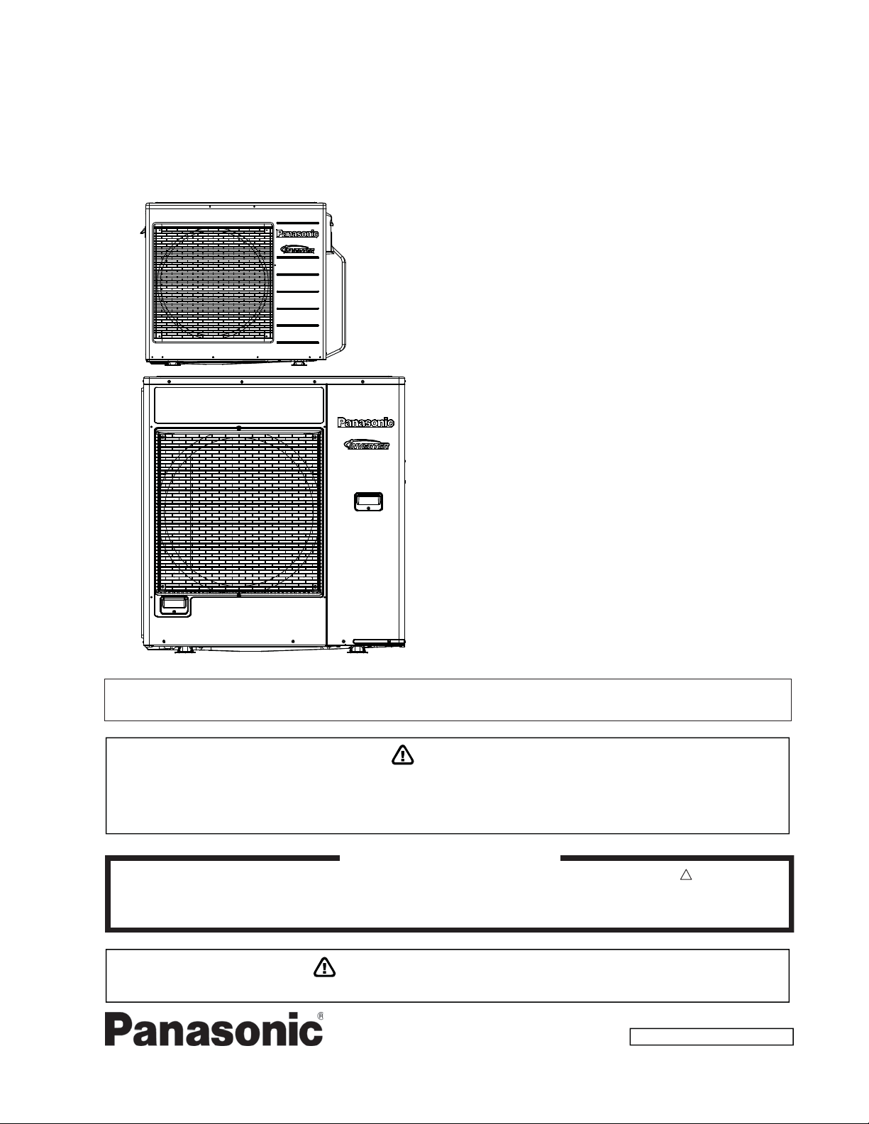
Outdoor Unit
CU-3E19RBU
CU-4E24RBU
Destination
U.S.A.
Canada
Please file and use this manual together with the service manual for Model No. CS-E9RKUAW CS-E12RKUAW CS-E18RKUAW,
CS-E24RKUAW, CS-ME7RKUA, CS-E12RB4UW, CS-E18RB4UW, CS-ME5RKUA, Order No. PAPAMY1501049CE,
PAPAMY1503094CE, PAPAMY1503095CE, PAPAMY1505112CE.
WARNING
This service information is designed for experienced repair technicians only and is not designed for use by the general public.
It does not contain warnings or cautions to advise non-technical individuals of potential dangers in attempting to service a product.
Products powered by electricity should be serviced or repaired only by experienced professional technicians. Any attempt to
service or repair the product or products dealt with in this service information by anyone else could result in serious injury or death.
IMPORTANT SAFETYNOTICE
There are special components used in this equipment which are important for safety. These parts are marked by in the Schematic
Diagrams, Circuit Board Diagrams, Exploded Views and Replacement Parts List. It is essential that these critical parts should be replaced
with manufacturer’s specified parts to prevent shock, fire or other hazards. Do not modify the original design without permission of
manufacturer.
PRECAUTION OF LOW TEMPERATURE
In order to avoid frostbite, be assured of no refrigerant leakage during the installation or repairing of refrigerant circuit.
© Panasonic Corporation 2015
!
Page 2
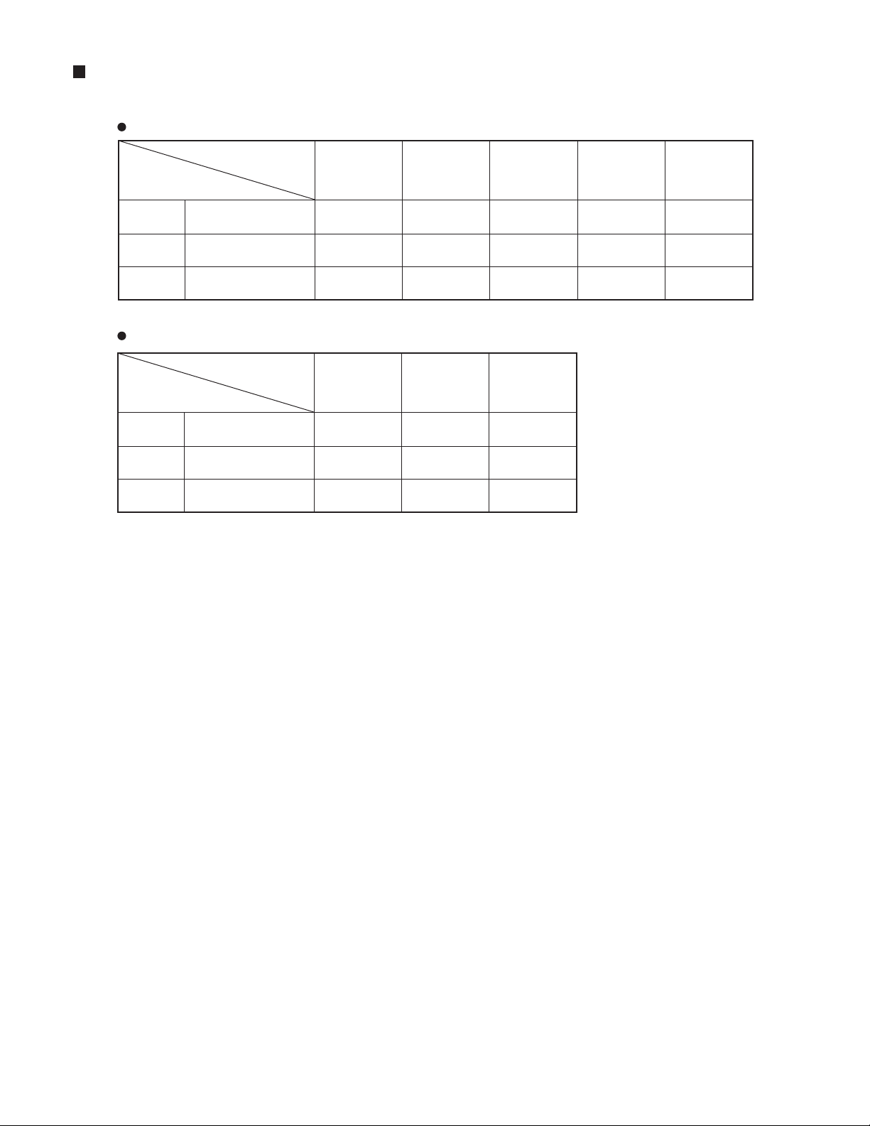
APPLICABLE INDOOR UNITS
Wall Mounted Type
Indoor Unit
CS-MKS7NKU
Multi-Outdoor Unit
CS-MKS9NKU CS-MKS12NKU CS-MKS18NKU CS-MKS24NKU
3-Room
4-Room
4-Room
CU-3KS19NBU
CU-4KS24NBU
CU-4KS31NBU
Semi-Concealed Type
Indoor Unit
Multi-Outdoor Unit
3-Room
4-Room
4-Room
CU-3KS19NBU
CU-4KS24NBU
CU-4KS31NBU
YES
YES
YES
CS-MKS9NB4U
&
CZ-18BT1U
YES
YES
YES
YES
YES
YES
CS-MKS12NB4U
&
CZ-18BT1U
YES
YES
YES
YES
YES
YES
CS-KS18NB4UW
&
CZ-18BT1U
YES
YES
YES
YES
YES
YES
NO
YES
YES
6
Page 3
9. Installation Information
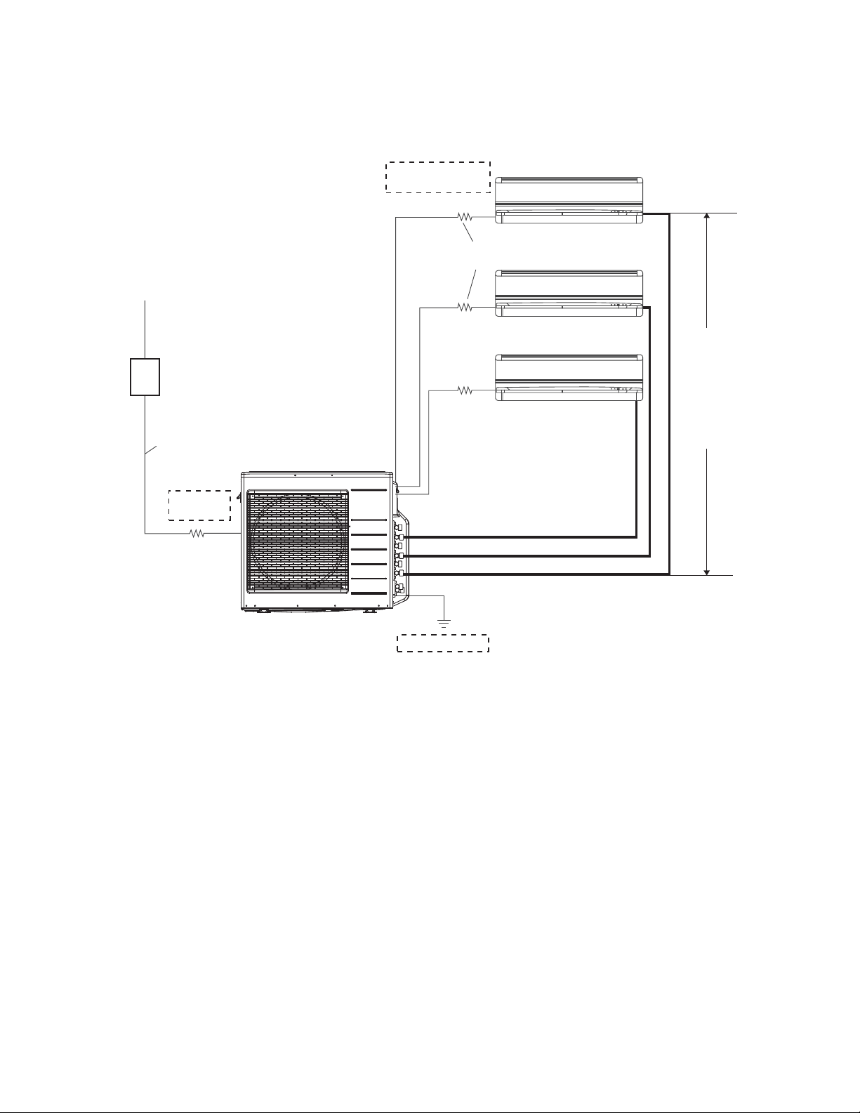
9.1 CU-3E19RBU
9.1.1 Check Points
Indoor/outdoor unit
connection cables
(Not included in the unit)
Outdoor unit power supply:
Single-phase 208-230V, 60Hz
30A switch
(circuit breaker)
(Not included in the unit)
Flexible cord x 3 core
(Not included in the unit)
Outside
wiring work
Unit C
Unit A Maximum pipe length: 25 m (82.0 ft)
Unit B Maximum pipe length: 25 m (82.0 ft)
Unit C Maximum pipe length: 25 m (82.0 ft)
Grounding work
Flexible cord x 4 core
(polychloroprene sheathed)
(Not included in the unit)
Unit B
Flexible cord x 4 core
(polychloroprene sheathed)
(Not included in the unit)
Unit A
Applicable connecting tube kit:
CZ-3F type
Total maximum pipe length: 50 m (164.0 ft)
Air purging: Air purging by vacuum pump.
Allowable
elevation:
15 m (49.2 ft) max.
The allowable
elevation between
each of the indoor
units and between
the indoor and
outdoor units.
29
Page 4
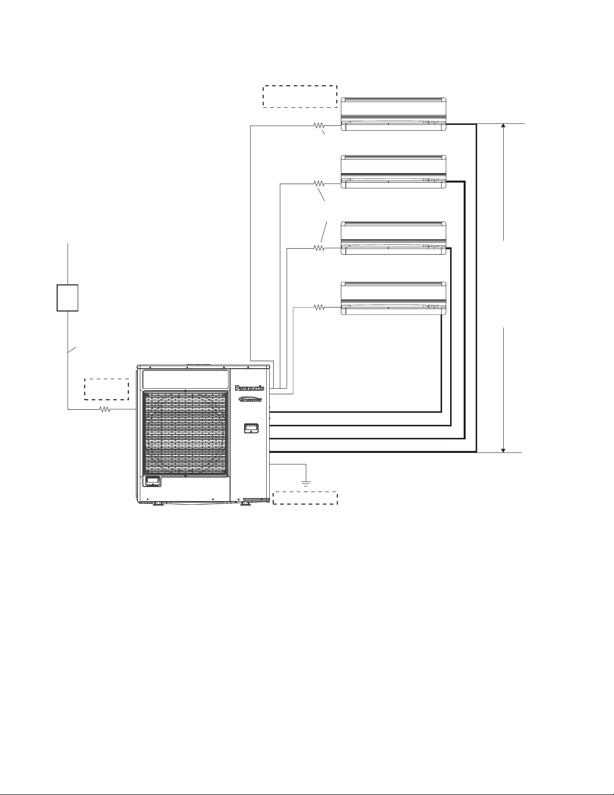
9.2 CU-4E24RBU
9.2.1 Check Points
Indoor/outdoor unit
connection cables
(Not included in the unit)
Flexible cord x 4 core
Unit D
(polychloroprene sheathed)
(Not included in the unit)
Outdoor unit power supply:
Single-phase 208-230V, 60Hz
45A switch
(circuit breaker)
(Not included in the unit)
Flexible cord x 3 core
(Not included in the unit)
Outside
wiring work
Unit C
Flexible cord x 4 core
(polychloroprene sheathed)
(Not included in the unit)
Unit B
Flexible cord x 4 core
(polychloroprene sheathed)
(Not included in the unit)
Unit A
Applicable connecting tube kit:
CZ-3F type
Unit A Maximum pipe length: 25 m (82.0 ft)
Unit B Maximum pipe length: 25 m (82.0 ft)
Unit C Maximum pipe length: 25 m (82.0 ft)
Unit D Maximum pipe length: 25 m (82.0 ft)
Total maximum pipe length: 70 m (229.6 ft)
Grounding work
Air purging: Air purging by vacuum pump.
Allowable
elevation:
15 m (49.2 ft) max.
The allowable
elevation between
each of the indoor
units and between
the indoor and
outdoor units.
30
Page 5
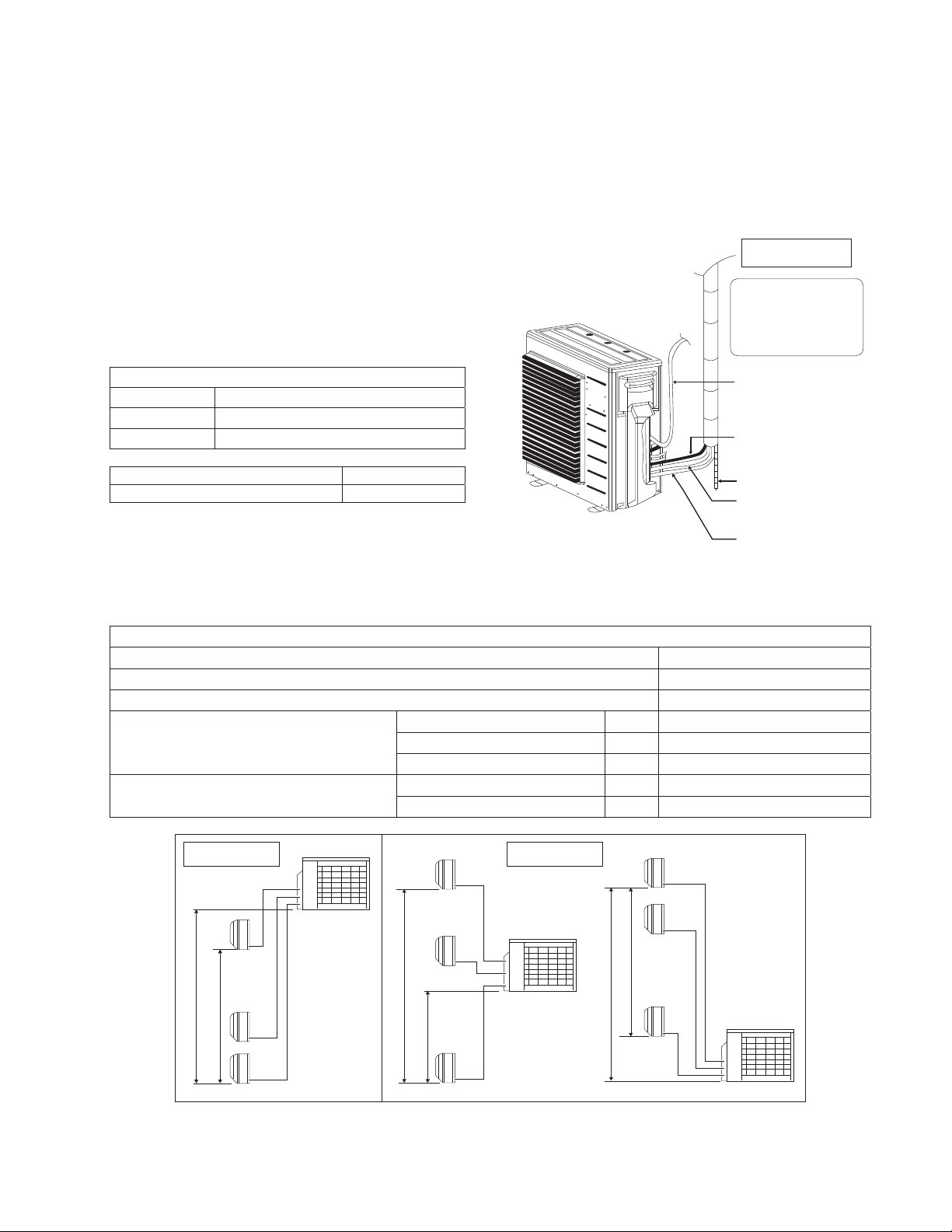
10. Installation Instruction
10.1 CU-3E19RBU
10.1.1 Select The Best Location
If an awning is built over the unit to prevent direct
sunli
ght or rain, be careful that heat radiat
the con
denser is not obstructed.
There should not be any animal or plant which
coul
d be affected by hot air discharged.
Keep the spaces indicated by arrows from
ceiling, fence or other obstacles.
Do not place any obstacles
rt circuit of the discharged air.
sho
which may cause a
Recommended installation height for outdoor un
sho
uld be above the seasonal snow
ion from
wall,
level.
10.1.1.1 Outdoor Unit Installation
Diagram
Installation parts you
should purchase (Ú)
It is advisable to avoid more
than 2 blockage directions.
For better ventilation &
it
multiple-outdoor installation,
please consult authorized
dealer/specialist.
Refrigerant piping size
Outdoor Unit CU-3E19**
Liquid - side ø1/4" (ø6.35 mm) thickness 1/32" (t0.8 mm)
Gas - side ø3/8" (ø9.52 mm) thickness 1/32" (t0.8 mm)
Outdoor Unit CU-3E19**
Min. total piping length for additional gas 98.4 ft (30 m)
If total piping length of all indoor units exceeds the
minimum len
with 0.2 oz (20g) of refrigerant (R410A) for ea
addition
Allowable piping length of each indoor unit (min. ~ max.) 9.8 ft ~ 82.0 ft (3 m ~ 25 m)
Allowable total piping length of all indoor unit 164.0 ft (50 m) or less
Height difference between indoor and outdoor unit
Height difference between indoor unit
gth listed above, additionally charge
al feet (meter) of piping.
Outdoor Unit CU-3E19***
ch
Allowable piping length
Outdoor unit located on upper side
Outdoor unit located otherwise
Outdoor unit located otherwise
Outdoor unit located on upper side
Outdoor unit located otherwise
This illustration is for explanation purposes only.
•
* Note:
Respective indoor unit installation procedure shall refer to
instruction manual provided in the indoor unit packaging.
g
h
k
i
j
Power supply cord (Ú)
(Conduit)
Connection cable (Ú)
(Conduit)
Additional drain hose (Ú)
1
/4" (6.35 mm)
Liquidsidepiping(Ú)
3
/8"(9.52mm)
Gas side piping (Ú)
49.2 ft (15 m) or less
24.6 ft (7.5 m) or less
49.2 ft (15 m) or less
24.6 ft (7.5 m) or less
49.2 ft (15 m) or less
Outdoor unit located
on upper side
g
i
Outdoor unit
j
h
tinuroodnItinuroodnI
31
Outdoor unit located
otherwise
Outdoor unit
k
Indoor unit
j
Outdoor unit
Page 6
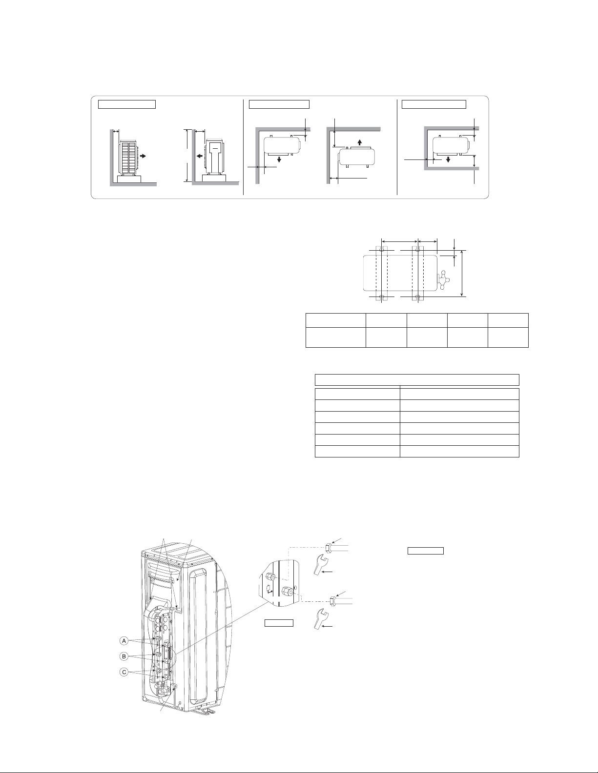
Outdoor Unit Installation Guidelines
U
n
nch(mm)
Where a wall or other obstacle is in the path of outdoor unit’s intake or exhaust airflow, follow the installation
guidelines below.
For any of the below installation patterns, the wall height on the exhaust side should be 47-1/4" (120
0 mm) or
less.
Wall facing one side
More than 315/16" (100)
471/4" (1200)
or less
More than
393/8" (1000)
Walls facing two side Walls facing three side
10.1.2 Install The Outdoor Unit
After selecting the best location, start installation
to Indoor/O
Fix the unit on concrete or rigid fram
1.
and ho
(ø10 mm
2.
When installing on a roof, please consid
stron
Please fasten the installation stand firmly
3.
utdoor Unit Installation Diag
rizontally by bolt nut (ø13/32
)).
g winds and earthquakes
ram.
e firmly
"
er
.
with
bolt or nails.
10.1.3 Connect The Piping
Remove the control board cover (resin) from the
outdoo
r unit by loosening three scre
ecting The Piping To Outdoor Unit
Conn
Decide piping length and then cut by using pipe cutter.
Remove burrs from cut edge. Make flare after
inserting the flare nut (locate at valve) onto the copper
pipe.
Align center of piping to valves and then tighten with
torque wrench to the specified torque as stated in the
table.
ws.
More than
315/16" (100)
More than
315/16" (100)
More than
393/8" (1000)
More than
1113/16" ( 300)
weivpoTweivediS
More
than
315/16"
(100)
AB
More than
315/16" (100)
More than
393/8" (1000)
To p v i ew
C
it : i
D
Model A B C D
CU-3E19***
24-1/8"
(613 mm)
5-5/32"
(131 mm)
5/8"
(16 mm)
14-3/16"
(360.5 mm)
Do not over tighten, over tightening may cause gas leakage
Piping size Torque
1/4" [6.35 mm] 13.3 Ibf•ft [18 N•m (1.8 kgf•m)]
3/8" [9.52 mm] 31.0 Ibf•ft [42 N•m (4.3 kgf•m)]
1/2" [12.7 mm] 40.6 Ibf•ft [55 N•m (5.6 kgf•m)]
5/8" [15.88 mm] 47.9 Ibf•ft [65 N•m (6.6 kgf•m)]
3/4" [19.05 mm] 73.8 Ibf•ft [100 N•m (10.2 kgf•m)]
Gas Le
ak Checking
Pressure test to system to 400 PSIG with dry nitrogen,
in stages. Thoroughly leak check the system.
If the pressure holds, release the nitrogen and
proceed to section 10.1.4.
Screws
Screw
Control Board Cover (Resin)
Liquid side
Gas side
Male side
Flare Nut
(Connection Pipe)
Torque Wrench for Flare Nut
Flare Nut
(Connection Pipe)
Torque Wrench for Flare Nut
Female side
Applicable to
Liquid and Gas side of
CS-ME5*** CS-E12***
CS-ME7*** CS-E18***
CS-E9***
32
Page 7
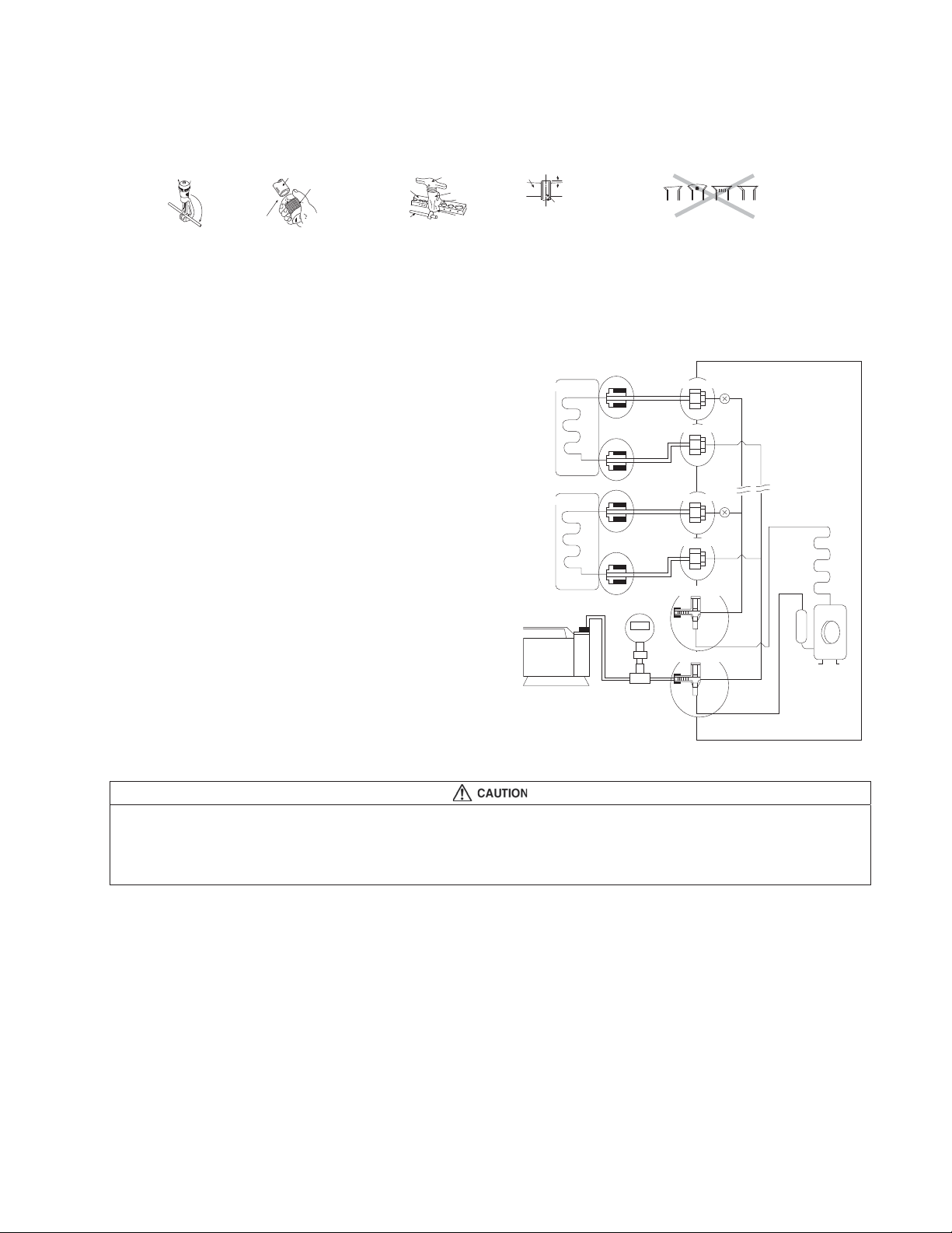
CUTTING AND FLARING THE PIPING
0
–1/
Please cut using pipe cutter and then remove the burrs.
1.
2. Remove the burrs by using reamer. If burrs is not removed, gas leakage may be caused.
s.
32
"
Copper pipe
pe.
ŶImproper flaringŶ
Inclined Surface
When properly flared, the internal surface
of the flare will evenly shine and be of
even thickness. Since the flare part
comes into contact with the connections,
carefully check the flare finish.
damaged
Cracked Un even
thickness
Turn the piping end down to avoid the metal powder entering the pi
3.
Please make flare after inserting the flare nut onto the copper pipe
1. To cut
Poin t dow n
2. To remove burrs
Pipe
Reamer
Bar
Clamp handle
3. To flare
Handle
Yo k e
Core
Red arrow mark
Bar
(0-0.5 mm)
10.1.4 Evacuation Of The Equipment
WHEN INSTALLING AN AIR CONDITIONER, BE SURE TO EVACUATE THE AIR INSIDE THE INDOOR UNIT AND
PIPES in the following procedure.
Connect a charging hose with a push pi
1.
the Low
port of the ga
2.
Connect the micron gauge between
pump an
side of a charging set and the
3-way valve.
s side
vacuum
d service port of outdoor units.
3. Turn on the power switch of the vacuum pump
and ma
ke sure that connect digital micron
gauge and to pull down to a value of 50
microns.
4.
To make sure micron gauge a value 500
microns and close the lo
rging set and turn off the vacuum pu
cha
Disconnect the vacuum pump house from
5.
ce port of
servi
Tighten the service port caps of gas side
6.
the 3-way valve.
w side valve of the
3-way valve at a torque of 13.3 Ibf•ft (18 N•m)
with a torque wrench.
Remove the valve caps
7.
of both of the 2-way
valve and 3-way valve. Position both of the
valves to “Open” using a hexagonal wrench
(5/32" (4 mm)).
Mount valve caps onto the 2-way valve and
8.
way valve.
3-
o
Be sure to check for gas leakage.
n to
service
0
mp.
the
Indoor Unit
Indoor Unit
Vacuum
pump
Tube connector
Liquid side
Tube connector
Gas
side
Tube connector
Liquid side
Tube connector
Gas
side
Liquid side 3-way valve
Gas side 3-way valve
Close
Close
Outdoor unit
If micron gauge value does not descend 500 microns, take the following measures:
If the leak stops when the piping connections are tightened further, continue working from step e
-
-
If the leak does not stop when the connections are retightened, re
-
Do not release refrigerant during piping work for installation and reinstallation.
Take care when handling the liquid refrigerant, it may cause frostbit
-
pair location of leak.
e.
.
33
Page 8
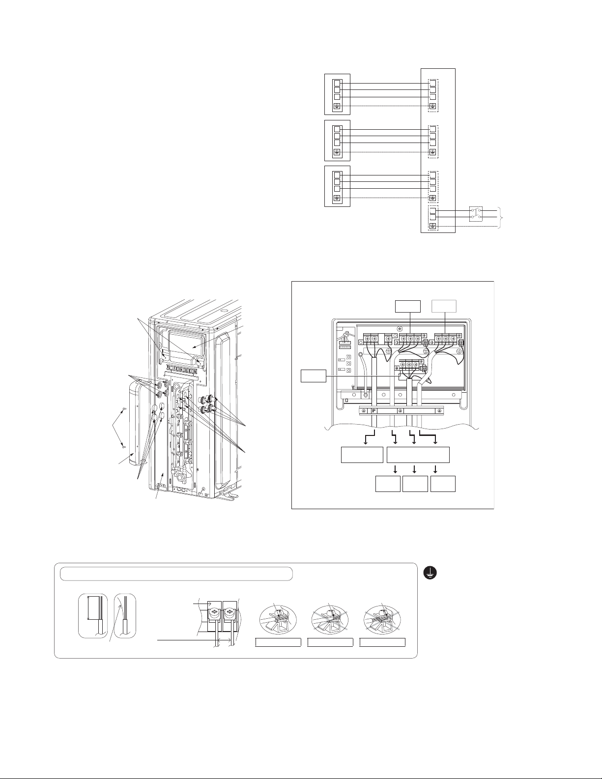
10.1.5 Connect The Cable To The Outdoor Unit
1. Remove Control Board Cover (Metal) by
loosening 2
Remove Valve Cover (Metal) by looseni
2.
rews.
sc
3.Remove Plugs
4. Fix the conduit connectors to the knock
s with lock-nuts, then secure them.
hole
5. Connecting wire between indoor unit and
outdoo
r unit should be UL listed or
approved 4 condu
in accordance with local electric codes.
6. Wire Connection to the power supp
30V 60Hz) through circuit breake
(208/2
o Connect the UL liste
wire
s minimum AWG12 to
board, and co
s to circuit breaker.
wire
7.
Connect the power supply cord a
con
necting wires between indoor unit an
r unit according to the diagram as
outdoo
shown.
ws.
scre
.
ctor wires minimum AWG1
d or CSA approved
nne
ct to other end of the
ng 2
out
CSA
6
ly
r.
the terminal
nd
d
Terminal
1
2
Indoor
Unit A
3
Terminal
1
2
Indoor
3
Unit B
Terminal
1
Indoor
2
Unit C
3
Each indoor unit must have its ownconduit for the
wires between the indoor andoutdoor unit but the
power supply for the outdoor unitmust be in a separate
conduit to prevent potential communicationproblems.
208/230V min AWG16
208/230V min AWG16
208/230V min AWG16
Grounding wire min AWG16
208/230V min AWG16
208/230V min AWG16
208/230V min AWG16
Grounding wire min AWG16
208/230V min AWG16
208/230V min AWG16
208/230V min AWG16
Grounding wire min AWG16
Outdoor Un it
Terminal
1
2
3
1
2
3
1
2
3
L1
L2
Unit A
Unit B
Unit C
Disconnect
Switch
Field supply
Grounding wire
Power Supply
Single Phase
208/230V 60Hz
min AWG12
Top panel
Screws
Lock Nuts
Screws
Val ve
Cover
(Metal)
Plugs
Side Panel
8.
For wire stripping and connection requirement, refer to the diagram below.
9.
Secure the power supply cord and connection cables onto the control board with the holde
Attach the control board cover (metal and resin) and valve cover back to the original position with screw.
10.
Control Board
Cover (Metal)
Connectors
Knock Out
Holes
WIRE STRIPPING AND CONNECTING REQUIREMENT
Wire stripping
"
16
/
1
"±
32
(10±1 mm)
/
13
Noloosestrandwheninserted
Indoor/outdoor
connecting
terminal board
7
/32" (5 mm)
or more
(gap between
wires)
Conductor fully
CU-3E19***
Unit C
Power Supply
Cord
Indoor
Unit A
inserted
ACCEPT PROHIBITED PROHIBITED
Conductor over
inserted
Conductor not
fully inserted
Unit A
Indoor & outdoor
connection cable
Indoor
Unit C
Ground wire must be Yellow/
•
Green (Y/G) in colour and
longer than other AC wires for
safety reasons.
Unit B
Indoor
Unit B
r.
This equipment must be
properly earthed.
34
Page 9
10.1.6 Heat Insulation
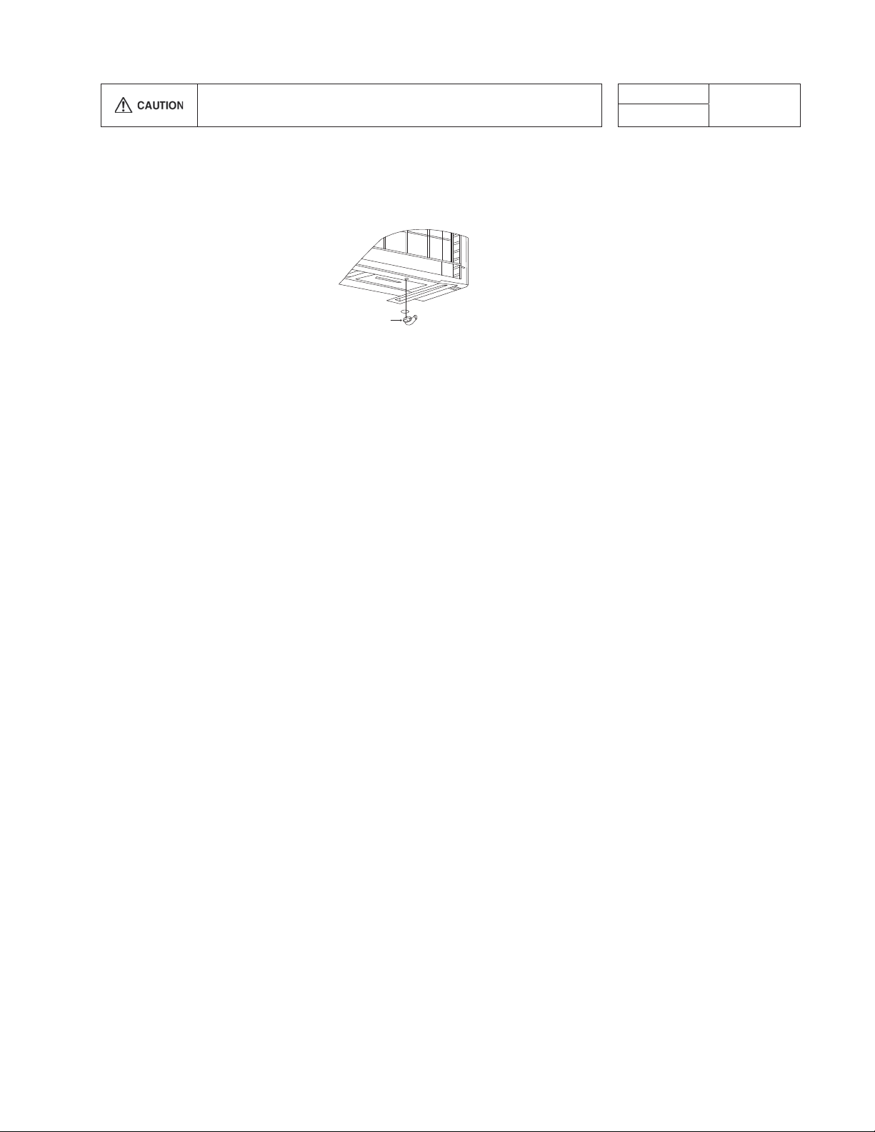
Use a material
pipes. Be sure to insulate both the gas-side and liquid-side pipes. If the pipes are
not adequately insulated, condensation or water leakages may occur.
with good heat-resistant properties as the heat insulation for the
Liquid-side pipes
Gas-side pipes
10.1.7 Disposal Of Outdoor Unit Drain Water
If a drain elbow is used, the unit should be placed on a stand which is taller than 1-31/32" (50 mm).
If the unit is used in an area where temperature falls below 32°F (0°C) for 2 or 3 days in successi
recomme
nded not to use a drain elbow, for the drain water freezes and the fan will not rotate
Drain elbow
Install the hose at an angle so that
the water smoothly flows out.
on, it is
.
Material shall
withstand 248°F
(120°C) or higher
35
Page 10
10.2 CU-4E24RBU
n
str
u
anu
alp
r
dedinth
ein
doorunitp
ackagin
g
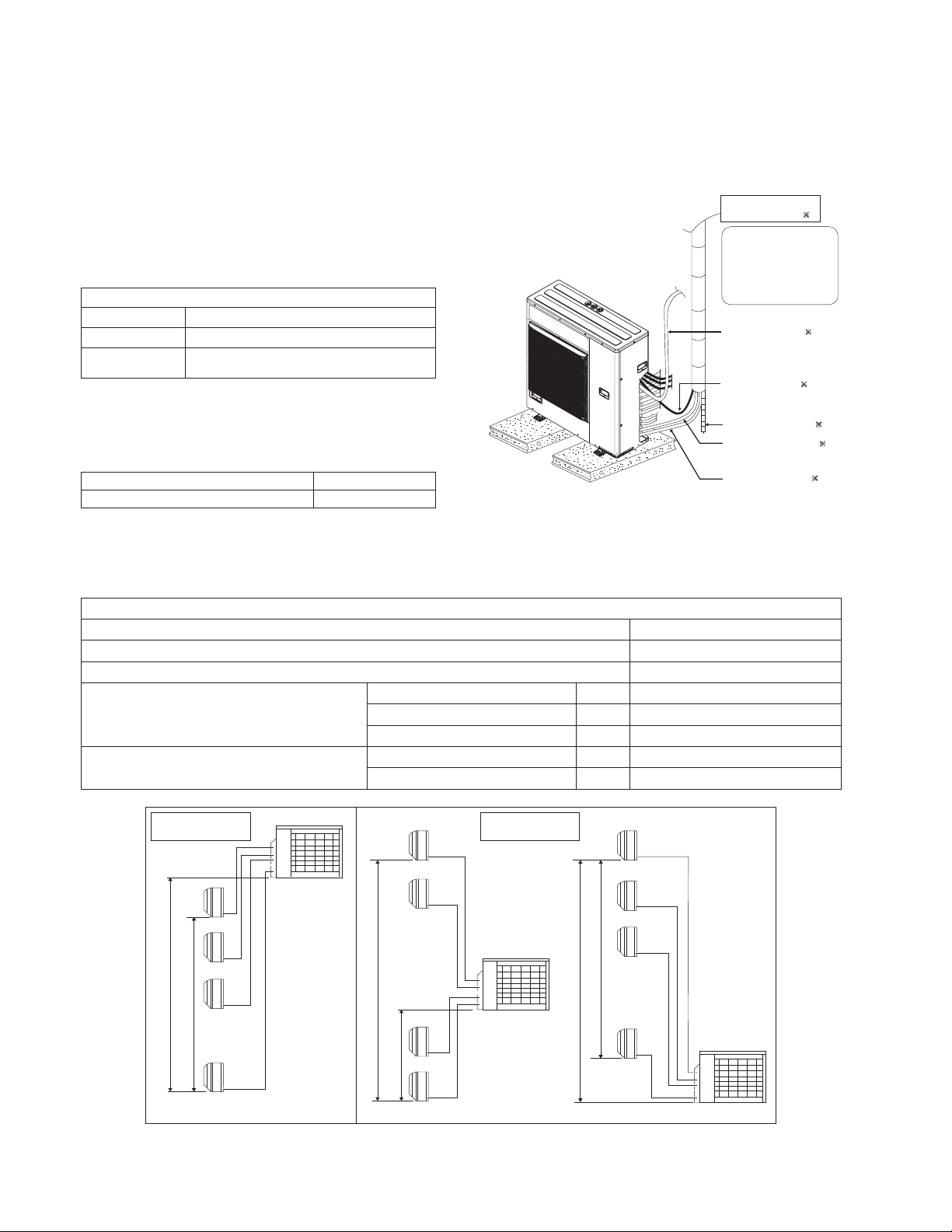
10.2.1 Select The Best Location
If an awning is built over the unit to prevent direct
sunli
ght or rain, be careful that heat radiat
the con
denser is not obstructed.
There should not be any animal or plant which
coul
d be affected by hot air discharged.
Keep the spaces indicated by arrows from
ceiling, fence or other obstacles.
Do not place any obstacles
rt circuit of the discharged air.
sho
Refrigerant piping size
Outdoor Unit CU-4E24***
Liquid - side ø1/4" (ø6.35 mm) thickness 1/32" (t0.8 mm)
Gas - side
ø3/8" (ø9.52 mm) thickness 1/32" (t0.8 mm)
(ø1/2" (ø12.7 mm) thickness 1/32" (t0.8 mm))
which may cause a
* In the case of indoor unit is CS-E24***, a gas-
pipe of ø1/2" (ø12.7 mm) thickness 1/32
(t0.8 mm) mu
(pipe size
st be used together
expand
er)
ion from
wall,
"
with CZ-MA2P
10.2.1.1 Outdoor Unit Installation
Diagram
Installation parts you
should purchase (
It is advisable to avoid
more than 2 blockage
directions. For better
ventilation & multipleoutdoor installation,
please consult authorized
dealer/specialist.
Power supply cord (
Connection cable (
Additional drain hose (
1/4" Liquid side piping (
)
)
)
)
)
Outdoor Unit CU-4E24***
Min. total piping length for additional gas 147.6 ft (45 m)
If total piping length of all indoor units exceeds the
minimum len
with 0.2 oz
addition
Outdoor Unit CU-4E24***
Allowable piping length of each indoor unit (min. ~ max.) 9.8 ft ~ 82.0 ft (3 m ~ 25 m)
Allowable total piping length of all indoor unit 229.6 ft (70 m) or less
Height difference between indoor and outdoor unit
Height difference between indoor unit
gth listed above, charge ad
(20g) of refrigerant (R410A) for ea
al foot (meter) of piping.
Outdoor unit located
on upper side
Outdoor unit
ditionally
ch
Allowable piping length
Outdoor unit located on upper side
Outdoor unit located otherwise
Outdoor unit located otherwise
Outdoor unit located on upper side
Outdoor unit located otherwise
Outdoor unit located
otherwise
This illustration is for explanation purposes only.
•
* Note:
Respective indoor unit installation procedure shall refer to
ctionm
i
ovi
g
h
k
i
j
Indoor unit
3/8" Gas side piping ( )
49.2 ft (15 m) or less
24.6 ft (7.5 m) or less
49.2 ft (15 m) or less
24.6 ft (7.5 m) or less
49.2 ft (15 m) or less
.
j
j
g
i
Outdoor unit
k
h
Outdoor unittinuroodnItinuroodnI
36
Page 11
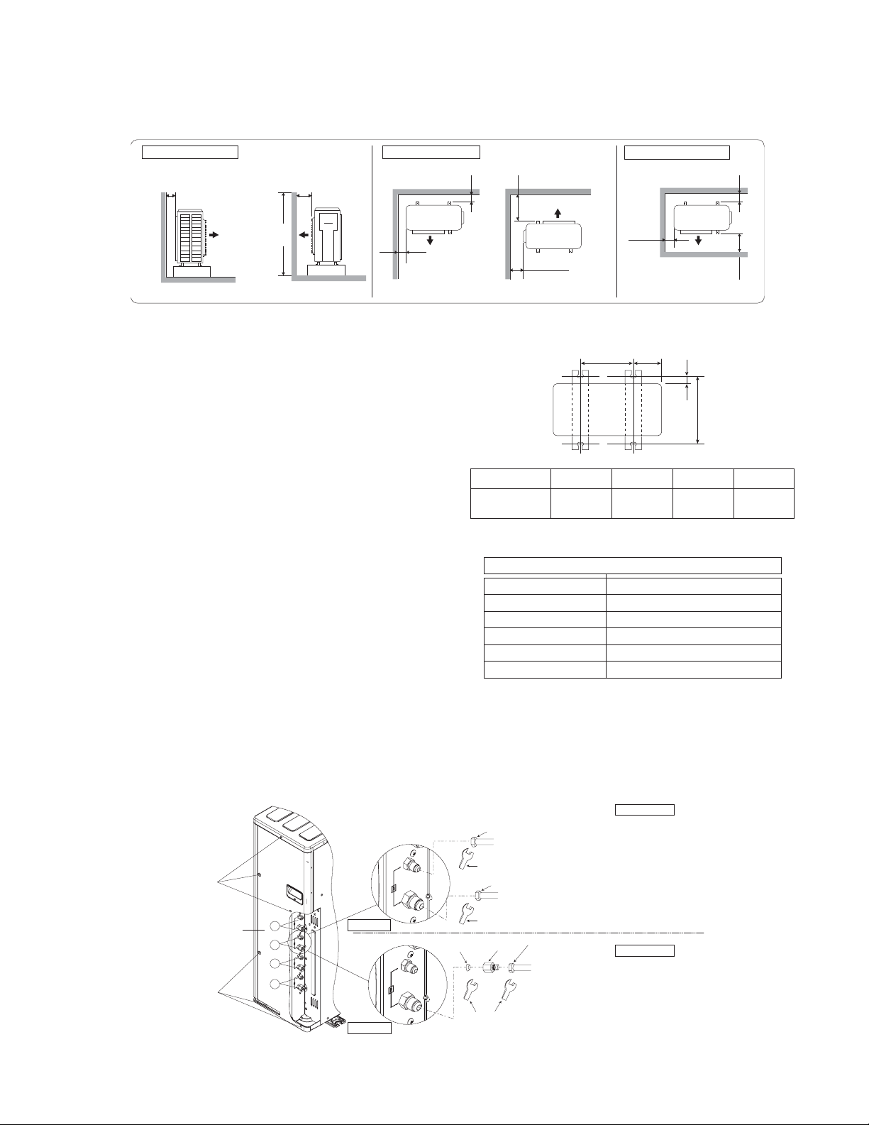
Outdoor Unit Installation Guidelines
(mm
)
C
Where a wall or other obstacle is in the path of outdoor unit’s intake or exhaust airflow, follow the installation
guidelines below.
For any of the below installation patterns, the wall height on the exhaust side should be 47-1/4" (120
0 mm) or
less.
Wall facing one side
More than 315/16" (100)
471/4" (1200)
or less
More than
3
/8" (1000)
39
Walls facing two side Walls facing three side
More than
3
10.2.2 Install The Outdoor Unit
After selecting the best location, start installation
to Indoor/O
1.
utdoor Unit Installation Diag
Firmly attach the unit horizontally to conc
or a rigi
d frame with bolts and nuts (ø13
ram.
rete
/32"
(ø10 mm)).
2.
When installing on a roof, please consid
g winds and earthquakes
stron
Please fa
bolts or n
sten the installation stand firmly
ails.
.
er
with
10.2.3 Connect The Piping
Remove the cabinet side plate (metal) from the
unit by loose
Connecting The Piping To Outdoor Unit
Decide piping length and then cut by using pipe cutter.
Remove burrs from cut edge. Make flare after
inserting the flare nut (locate at valve) onto the copper
pipe.
Align center of piping to valves and then tighten with
torque wrench to the specified torque as stated in the
table.
ning six screws.
More than
15
3
/16" (100)
15
/16" (100)
/16"
More than
315/16" (100)
More than
3
/8" (1000)
39
Top view
Unit : inch
C
D
weivpoTweivediS
More than
3
/8" (1000)
39
More than
13
/16" (300)
11
More
than
15
3
(100)
AB
Model A B C D
CU-4E24***
24-13/32"
(620 mm)
6-11/16"
(170 mm)
25/32"
(20 mm)
14-31/32"
(380.5 mm)
Do not over tighten, over tightening may cause gas leakage
Piping size Torque
1/4" [6.35 mm] 13.3 Ibf•ft [18 N•m (1.8 kgf•m)]
3/8" [9.52 mm] 31.0 Ibf•ft [42 N•m (4.3 kgf•m)]
1/2" [12.7 mm] 40.6 Ibf•ft [55 N•m (5.6 kgf•m)]
5/8" [15.88 mm] 47.9 Ibf•ft [65 N•m (6.6 kgf•m)]
3/4" [19.05 mm] 73.8 Ibf•ft [100 N•m (10.2 kgf•m)]
Gas Le
ak Checking
Pressure test to system to 400 PSIG with dry nitrogen,
in stages.
Thoroughly leak check the system.
If the pressure holds, release the nitrogen and
proceed to section 10.2.4.
Female side
Applicable to
Liquid and Gas side of
CS-ME5***,
CS-ME7***,
CS-E9***,
CS-E12***,
CS-E18***
Liquid side of
CS-E24***
Female side
Applicable to
Gas side of
CS-E24***
Screw
abinet side plate
Screw
Flare Nut
(Connection Pipe)
TorqueWrench for
Flare Nut
Flare Nut
(Connection Pipe)
A
B
C
D
Male side
Male side
TorqueWrench for
Flare Nut
Pipe Size
Expander
Packing
TorqueWrench for Flare Nut
and Pipe Size Expander
Flare Nut
(Connection Pipe)
37
Page 12
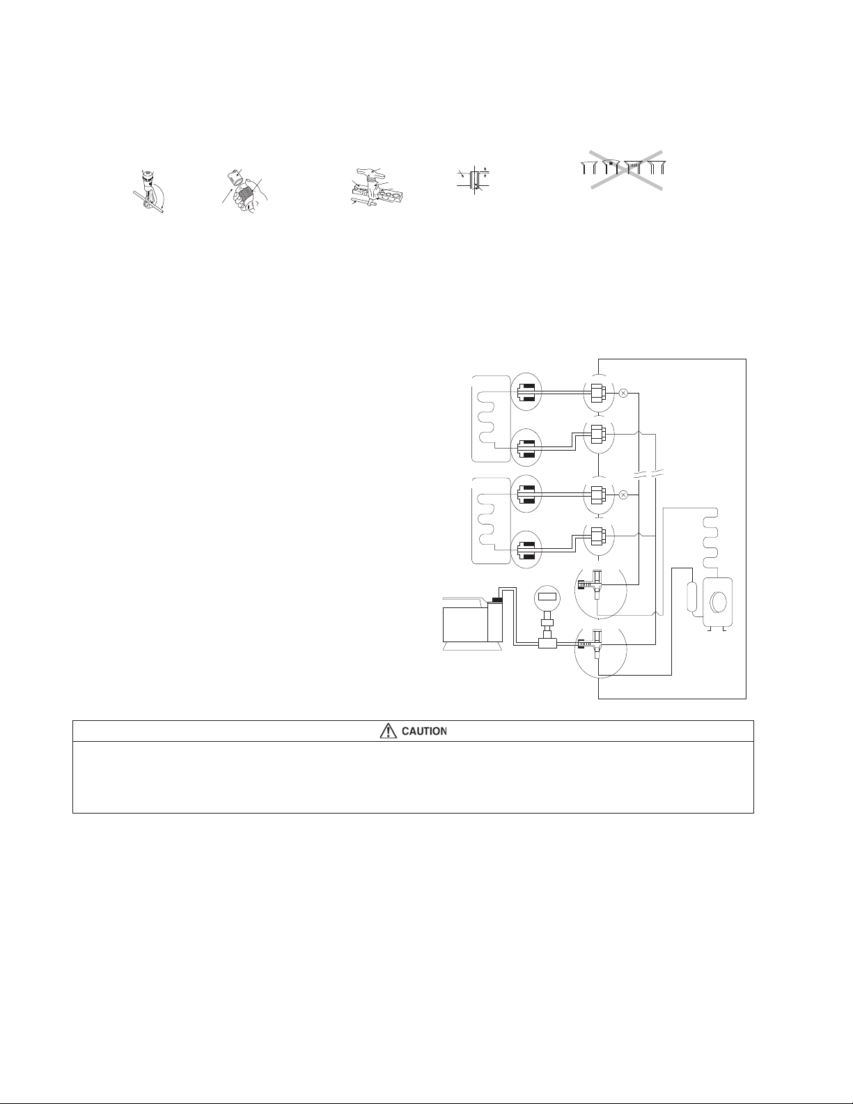
CUTTING AND FLARING THE PIPING
mproperfla
ring
are
d
Please cut using pipe cutter and then remove the burrs.
1.
2. Remove the burrs by using a reamer. If burrs are not removed, gas leakage may occur.
Turn the piping end down to avoid the metal powder entering the pi
3.
Please make flare after inserting the flare nut onto the copper pipe
pe.
s.
Ŷ
Cracked Uneven
thickness
1. To cut
Poin t down
2. To remove burrs
Pipe
Reamer
Bar
Clamp handle
3. To flare
Handle
Yo ke
Core
Red arrow mark
Bar
1
0–
/32"
(0-0.5 mm)
Copper pipe
ŶI
Inclined Surface
damaged
When properly flared, the internal
surface of the flare will shine evenly
and be of even thickness. Since the
flared part comes into contact with
the connections, carefully check the
finish.
fl
10.2.4 Evacuation Of The Equipment
WHEN INSTALLING AN AIR CONDITIONER, BE SURE TO EVACUATE THE AIR INSIDE THE INDOOR UNIT AND
PIPES in the following procedure.
Connect a charging hose with a push pi
1.
the Low
port of the ga
2.
Connect the micron gauge between
pump an
3.
Turn on the power switch of the vacuum
and ma
gaug
Make sure micron gauge indicates a value of
4.
500 micro
the cha
side of a charging set and the
3-way valve.
s side
d service port of outdoor units.
ke sure to conn
ect the digital micron
e and to lower to a value of 500 micron
ns and close the low side
rging set and turn off the vacuum
pump.
5.
Disconnect the vacuum pump house from
ce port of the 3-way valve.
servi
Tighten the service port caps of gas side
6.
3-way valve at a torque of 13.3 Ibf•ft (18 N•m)
with a torque wrench.
Remove the valve caps of both the 2-wa
7.
valve and 3-way valve. Position both of the
valves to “Op
en” using a hexagonal wren
(5/32" (4 mm)).
Mount valve caps onto the 2-way valve and
8.
way valve.
3-
o
Be sure to check for gas leakage.
n to
service
vacuum
pump
valve of
y
ch
the
Indoor Unit
s.
Indoor Unit
Vacuum
pump
Tube connector
Liquid side
Tube connector
Gas
side
Tube connector
Liquid side
Tube connector
Gas
side
Liquid side 3-way valve
Gas side 3-way valve
Close
Close
Outdoor unit
If micron gauge value does not descend 500 microns, take the following measures:
If the leak stops when the piping connections are tightened further, continue working from step e
If the leak does not stop when the connections are retightened, re
-
-
Do not release refrigerant during piping work for installation and reinstallation.
- Be careful when handling the liquid refrigerant, it may cause frostbite.
pair location of leak.
.
38
Page 13
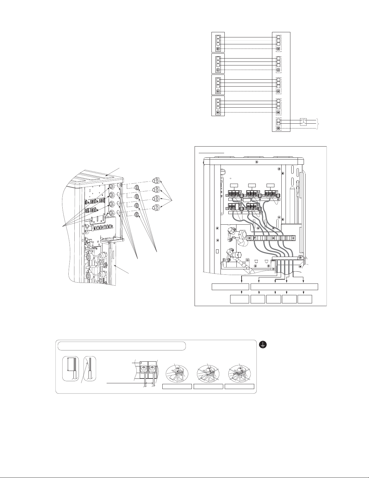
10.2.5 Connect The Cable To The Outdoor Unit
Outdoor
t
1. Remove Plugs.
2. Fix the conduit connectors to the knock
s with lock-nuts, then secure them.
hole
Connecting wire between indoor unit an
3.
outdoo
r unit should be UL listed or
approved 4 condu
in accordan
Wire Connection to the power supply
4.
(208/2
30V 60Hz) through circuit breake
Connect the UL liste
o
ctor wires minimum AWG1
ce with local electric code
d or CSA approved
wires minimum AWG12 to the terminal
board, and co
s to circuit breaker.
wire
Connect the power supply cord a
5.
con
necting wires between indoor unit an
r unit according to the diagram as
outdoo
ct to other end of the
nne
shown.
Top panel
out
d
CSA
6
s.
r.
nd
d
Terminal
1
2
Indoor
3
Unit A
Terminal
1
2
Indoor
Unit B
3
Terminal
1
Indoor
2
Unit C
3
Terminal
1
2
Indoor
3
Unit D
Each indoor unit must have its own conduit for the
wires between the indoor and outdoor unit but the
power supply for the outdoor unit must be in a separate
conduit to prevent potential communication problems.
208/230V min AWG16
208/230V min AWG16
208/230V min AWG16
Grounding wire min AWG16
208/230V min AWG16
208/230V min AWG16
208/230V min AWG16
Grounding wire min AWG16
208/230V min AWG16
208/230V min AWG16
208/230V min AWG16
Grounding wire min AWG16
208/230V min AWG16
208/230V min AWG16
208/230V min AWG16
Grounding wire min AWG16
CU-4E24***
Uni
Terminal
1
2
Unit A
3
1
2
Unit B
3
1
2
Unit C
3
1
2
Unit D
3
L1
L2
Unit CUnit A UnitB
Disconnect
Switch
Field supply
Grounding wire
Power Supply
Single Phase
208/230V 60Hz
min AWG12
Unit D
Lock
Nuts
Connectors
Plug
Knock Out
Holes
Rear panel
Indoor & Outdoor connection cablePower Supply Cord
Isolating
Devices
For wire stripping and connection requirement, refer to the diagram below.
6.
7.
Secure the power supply cord and connection cables onto the control board with the holde
8.
Fix the cabinet side plate (metal) back to the original position with screws.
Indoor
Unit A
WIRE STRIPPING AND CONNECTING REQUIREMENT
Wire stripping
"
16
/
1
"±
32
/
(10±1mm)
13
No loose strand when
inserted
Indoor/outdoor
connecting
terminal board
7
/32"(5mm)
or more
(gap between wires)
Conductor fully
inserted
Conductor over
inserted
Conductor not
fully inserted
ACCEPT PROHIBITED PROHIBITED
Ground wire shall be Yellow/
•
Green (Y/G) in colour and longer
than other AC wires for safety
reason.
Indoor
Indoor
Unit B
Indoor
Unit C
Unit D
r.
This equipment must be
properly ear thed.
39
Page 14
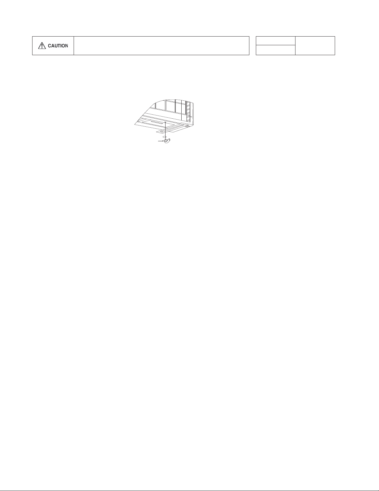
10.2.6 Heat Insulation
e
e
rsm
Use a material
pipes. Be sure to insulate both the gas-side and liquid-side pipes. If the pipes are
not adequately insulated, condensation or water leakages may occur.
with good heat-resistant properties as the heat insulation for the
Liquid-side pipes
Gas-side pipes
10.2.7 Disposal Of Outdoor Unit Drain Water
If a drain elbow is used, the unit should be placed on a stand which is taller than 1-31/32" (50 mm).
If the unit is used in an area where temperature falls below 32°F (0°C) for 2 or 3 days in successi
recomme
nded not to use a drain elbow, for the drain water freezes and the fan will not rotate
Drain elbow
Install the hose at an angle so that
wat
th
oothlyflows out.
.
Material shall
withstand 248°F
(120°C) or higher
on, it is
40
 Loading...