

Panasonic CS-A18DKD, CS-A24DKD, CU-A18DKD, CU-A24DKD Service Manual
Order No. MAC0501007C3
Air Conditioner
CS-A18DKD CU-A18DKD
CS-A24DKD CU-A24DKD
CONTENTS
Page Page
1 Features 2
2 Functions
2.1. Remote Control
2.2. Indoor Unit
2.3. Outdoor Unit
3 Product Specifications
3.1. CS-A18DKD CU-A18DKD
3.2. CS-A24DKD CU-A24DKD
4 Dimensions
4.1. Indoor Unit & Remote Control
4.2. Outdoor Unit
5 Refrigeration Cycle Diagram
6 Block Diagram
7 Wiring Diagram
8 Operation Details
10
10
11
12
13
14
15
3
3
4
5
6
6
8
8.1. Heating Operation 15
8.2. Cooling Operation
8.3. Soft Dry Operation
8.4. Automatic Operation
8.5. Operation Control
8.6. Indoor Fan Speed Control
8.7. Outdoor Fan Speed Control
8.8. Vertical Airflow Direction Control
8.9. Horizontal Airflow Direction Control
8.10. Powerful Operation
8.11. Quiet Operation
8.12. Ionizer Operation
8.13. Timer Control
8.14. Random Auto Restart Control
8.15. Remote Control Signal Receiving Sound
© 2004 Panasonic HA Air-Conditioning (M) Sdn Bhd
(11969-T). All rights reserved. Unauthorized copying
and distribution is a violation of law.
16
17
18
19
26
28
28
29
30
30
32
33
34
34
CS-A18DKD CU-A18DKD / CS-A24DKD CU-A24DKD
9 Operating Instructions 35
10 Installation Instructions
10.1. Safety Precautions
10.2. Indoor Unit
10.3. Outdoor Unit
11 2-way, 3-way Valve
11.1. Evacuation of the Equipment (For Europe & Oceania
Destination)
11.2. Air Purging of the Piping and Indoor Unit
12 Servicing Information
12.1. Indoor Electronic Controllers Removal Procedures
12.2. Cross Flow Fan and Indoor Fan Motor Removal
Procedures
12.3. Remote Control Reset
12.4. Auto OFF/ON Button
13 Troubleshooting Guide
13.1. Refrigeration cycle system
41
41
44
48
51
52
58
64
64
65
66
67
68
68
1 Features
• High efficiency.
• Compact design.
• Wider range of horizontal discharge air.
• Air Filter with function to reduce dust and smoke.
• Automatic air swing and manual adjusted by Remote
Control for horizontal and vertical airflow.
• Long installation piping up to 25 meter.
• Supersonic Air Purifying System with SUPER alleru-buster.
− Inactive various harmful airbone elements including
allergens, viruses and bacteria.
− Generated supersonic waves enhance the ability to
collect dust and dirt in the air.
14 Technical Data 70
14.1. Thermostat characteristics
14.2. Operation characteristics
15 Exploded View (Indoor Unit)
15.1. CS-A18DKD CS-A24DKD
16 Replacement Parts List (Indoor Unit)
16.1. CS-A18DKD CS-A24DKD
17 Exploded View (Outdoor Unit)
17.1. CU-A18DKD CU-A24DKD
18 Replacement Parts List (Outdoor Unit)
18.1. CU-A18DKD CU-A24DKD
19 Electronic Circuit Diagram
19.1. Indoor Unit & Outdoor Unit
19.2. Remote Control
19.3. Print Pattern Indoor Unit Printed Circuit Board
19.4. Print Pattern Indicator & Receiver Printed Circuit Board
19.5. Print PatternOutdoor Unit Printed Circuit Board
70
71
73
73
74
74
75
75
76
76
77
77
83
84
85
86
• Serviceability Improvement
− Removable and washable Front Panel.
• Quality Improvement
− Random auto restart after power failure for safety restart
operation.
− Gas leakage detection.
− Prevent Compressor reverse cycle.
− Inner protector to protect Compressor.
− Noise prevention during soft dry operation.
− Blue coated Condenser for high resistance to corrosion.
− Anti-dew formation control (Cooling & Soft Dry).
− Overload Protection Control (Heating).
− Outdoor Fan Control.
− Compressor High Pressure Control.
• Operation Improvement
− Quiet mode to provide quiet operation.
− Powerful mode to reach the desired room temperature
quickly.
− Ionizer control for generating negative ion in discharge
air.
− 24-hour timer setting.
2
2 Functions
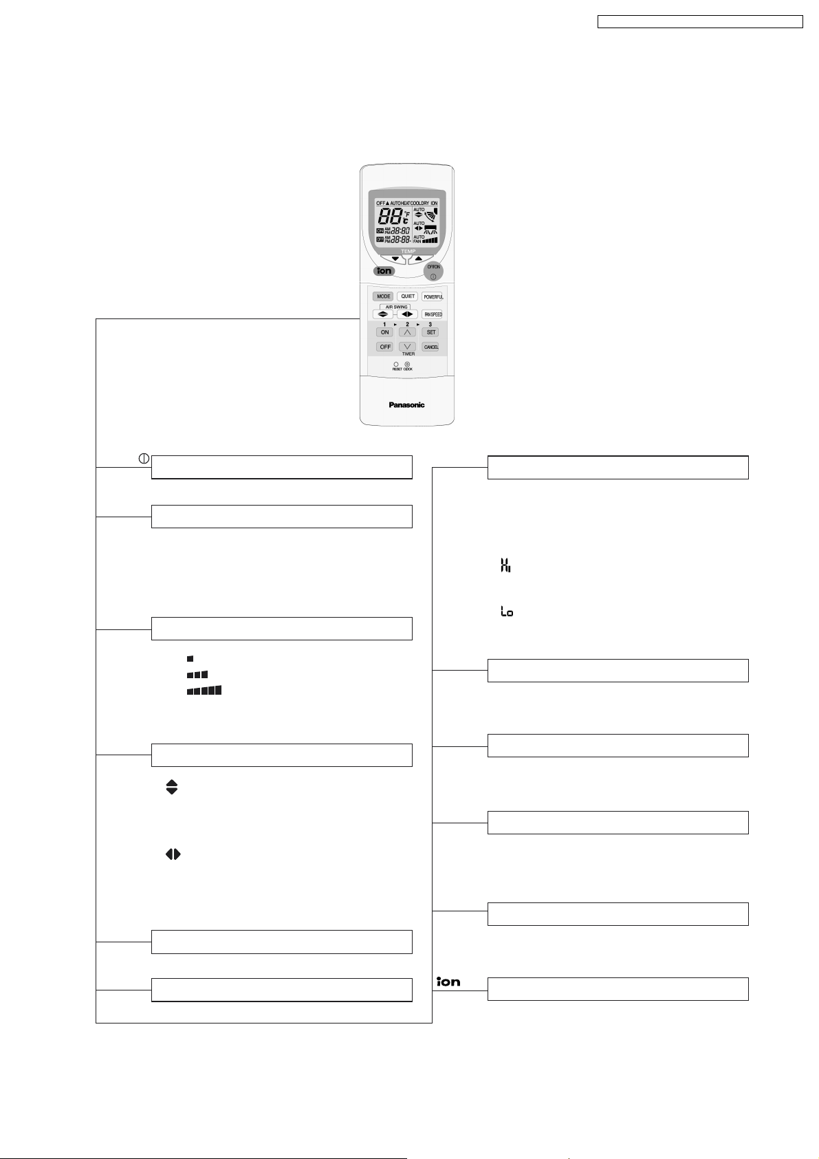
2.1. Remote Control
CS-A18DKD CU-A18DKD / CS-A24DKD CU-A24DKD
OFF / ON
MODE
FAN SPEED
AIR SWING
POWERFUL
Operation Start/Stop
Operation Mode Selection
•
•
•
•
AUTO
HEAT
COOL
DRY
Automatic Operation
Heating Operation Mode
Cooling Operation
Soft Dry Operation
Indoor Fan Speed Selection
• FAN Low Fan Speed
•
FAN Medium Fan Speed
•
FAN High Fan Speed
•
AUTO Automatic Fan Speed
FAN
Airflow Direction Control
• Vertical Automatic Airflow
Direction Control and Manual
Airflow Direction Control
(5 stages of adjustment).
•
Horizontal Automatic Airflow
Direction Control and Manual
Airflow Direction Control
(5 stages of adjustment).
Powerful Operation Start/Stop
TEMP.
ON-TIMER
OFF-TIMER
<
<
SET
CANCEL
CLOCK
Room Temperature Setting
Cooling, Soft Dry Operation.
• Increase or decrease set temperature
(16°C to 30°C)
Automatic Operation
Operation with 2°C higher than
•
standard temperature.
• Operation with standard temperature.
Operation with 2°C lower than
•
standard temperature.
Timer Operation Selection
• 24-hour, OFF / ON Real Timer Setting.
Time / Timer Setting
• Hours and minutes setting.
Timer Operation Set / Cancel
• ON Timer and OFF Timer setting and
cancellation.
Clock Setting
• Current time setting.
QUIET
Quiet Operation Start/Stop
Ionizer Operation Start/Stop
3
CS-A18DKD CU-A18DKD / CS-A24DKD CU-A24DKD
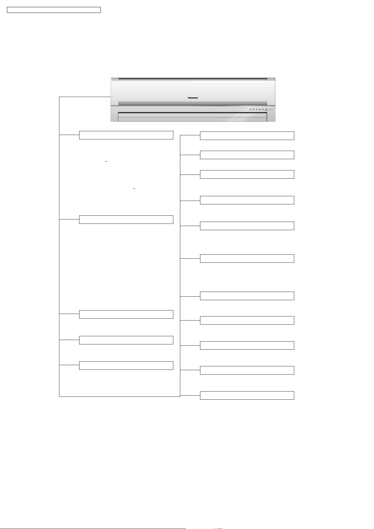
2.2. Indoor Unit
AUTO
OFF / ON
Automatic Operation Button
• Press for < 5 second to operate Automatic
operation mode.Use when the remote
control cannot be used.
• Press for > 5 second to operate Cooling
operation mode and compressor force
to on (“beep” sound will be heard). Used
when test running or servicing.
• Within 20 second of Cooling operation,
press continuously for > 5 second to enter
various setting mode. “beep, beep” sound
will be heard. (Used to toggle remote
control signal receiving sound or select
remote control transmission code.)
Operation Indication Lamps (LED)
• POWER (Green) ........ Lights up in operation,
TIMER (Orange) ....... Lights up in Timer
•
•
QUIET (Orange) ........ Lights up in Quiet
POWERFUL (Orange) .. Lights up in Powerful
•
ION (Green) ........... Lights up in Ionizer
•
SUPER
•
ALLERU-BUSTER
Operation Mode
•
Heating, Cooling, Soft Dry and Automatic
Operation.
Powerful Operation
• Reaches the desired room temperature
quickly.
Timer Operation
•
Delay OFF/ON Timer control.
(Blue)
blinks in Automatic
Operation judging.
Setting.
Operation.
Operation.
Operation.
...
Lights up in operation.
Quiet Operation
• To provide quiet operation.
Ionizer Operation
• Generate and discharge negative ion.
Random Auto Restart Control
• Unit will be restarted, when resume from
power failure, at previous setting.
Anti-Freezing Control
• To prevent indoor heat exchanger from
freezing.
Indoor Fan Speed Control
• Manual control fan speed
(High, Medium and Low).
• Automatic fan speed
Airflow Direction Control
••Vertical airflow control can be adjusted
automatically or manually by remote control.
Horizontal airflow control can be adjusted
automatically or manually by remote control.
Time Delay Safety Control
•
Restarting is inhibited for approximately
3 minutes.
7 Minutes Time Save Control
• To reduce the built up humidity inside
the room.
Anti-Dew Formation Control
• Anti-Dew Formation Control for indoor
unit discharge area.
Hot-Start Control
• To prevent cold air being discharge during
Heating operation starts.
Anti Cold Draft Control
• To prevent the cold draft during Heating
mode operation in thermo off condition.
4
2.3. Outdoor Unit
CS-A18DKD CU-A18DKD / CS-A24DKD CU-A24DKD
Compressor Reverse Rotation
Protection Control
• To protect compressor from reverse
rotation when there is an instantaneous
power failure.
Overload Protector
• Inner protector.
60 Secs. Forced Operation Control
• Once the compressor is activated, it
does not stop within the first 60 secs.
However, it stops immediately with
remote control stop signal.
Outdoor Fan Operation Control
• 6-pole induction motor (2 speed).
For Cooling or Soft Dry operation
•
Hi-speed ............. When outdoor
temperature reaches to 31°C.
Lo-speed ............. When outdoor
temperature reaches to 29°C.
For Heating operation
•
Hi-speed ............. When outdoor
temperature reaches to 13.5°C.
Lo-speed ............. When outdoor
temperature reaches to 15.5°C.
For Over-heating Protection, the Fan is
•
switched ON or OFF depending on the
piping temperature and the outdoor
temperature.
Deice Control
• To prevent frosting at outdoor heat
exchanger during Heating Operation.
4-Way Valve Control
• When the unit is switched to “OFF”
during Heating Operation, 4-way valve
stays at Heating position for 5 minutes.
5
CS-A18DKD CU-A18DKD / CS-A24DKD CU-A24DKD
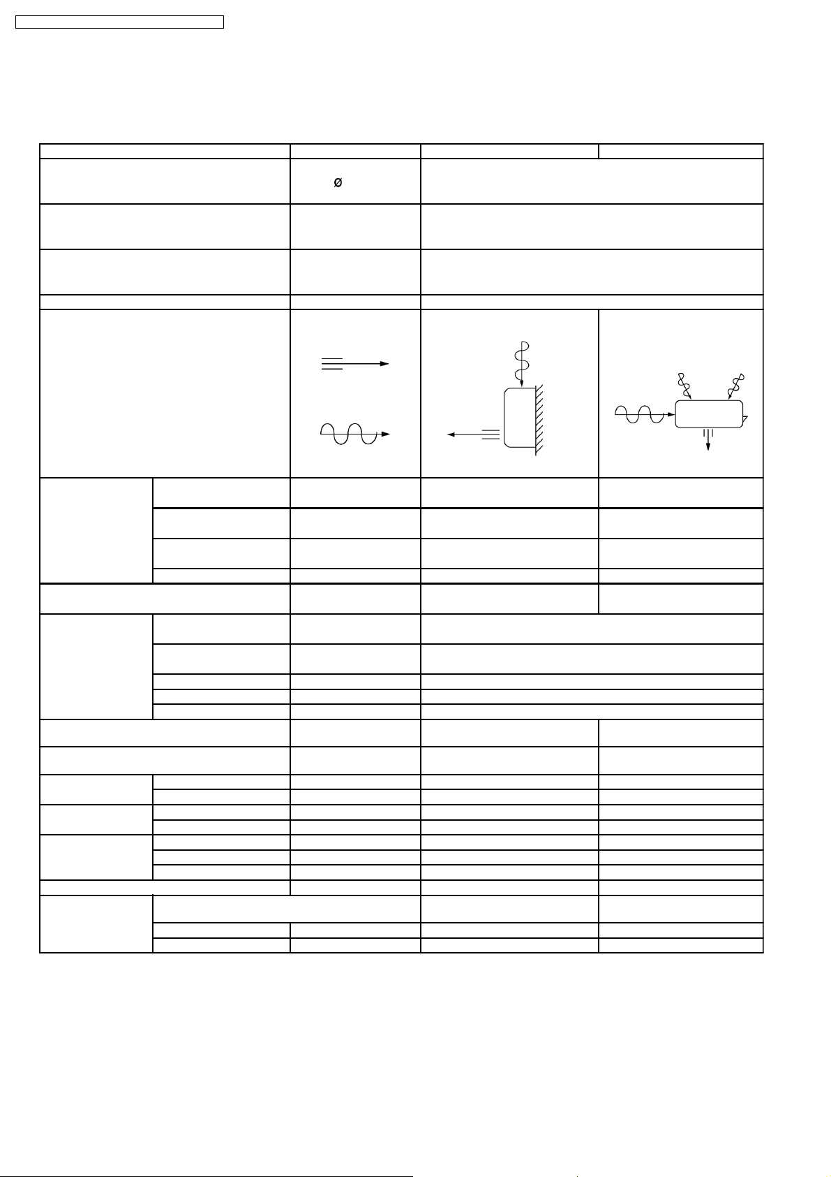
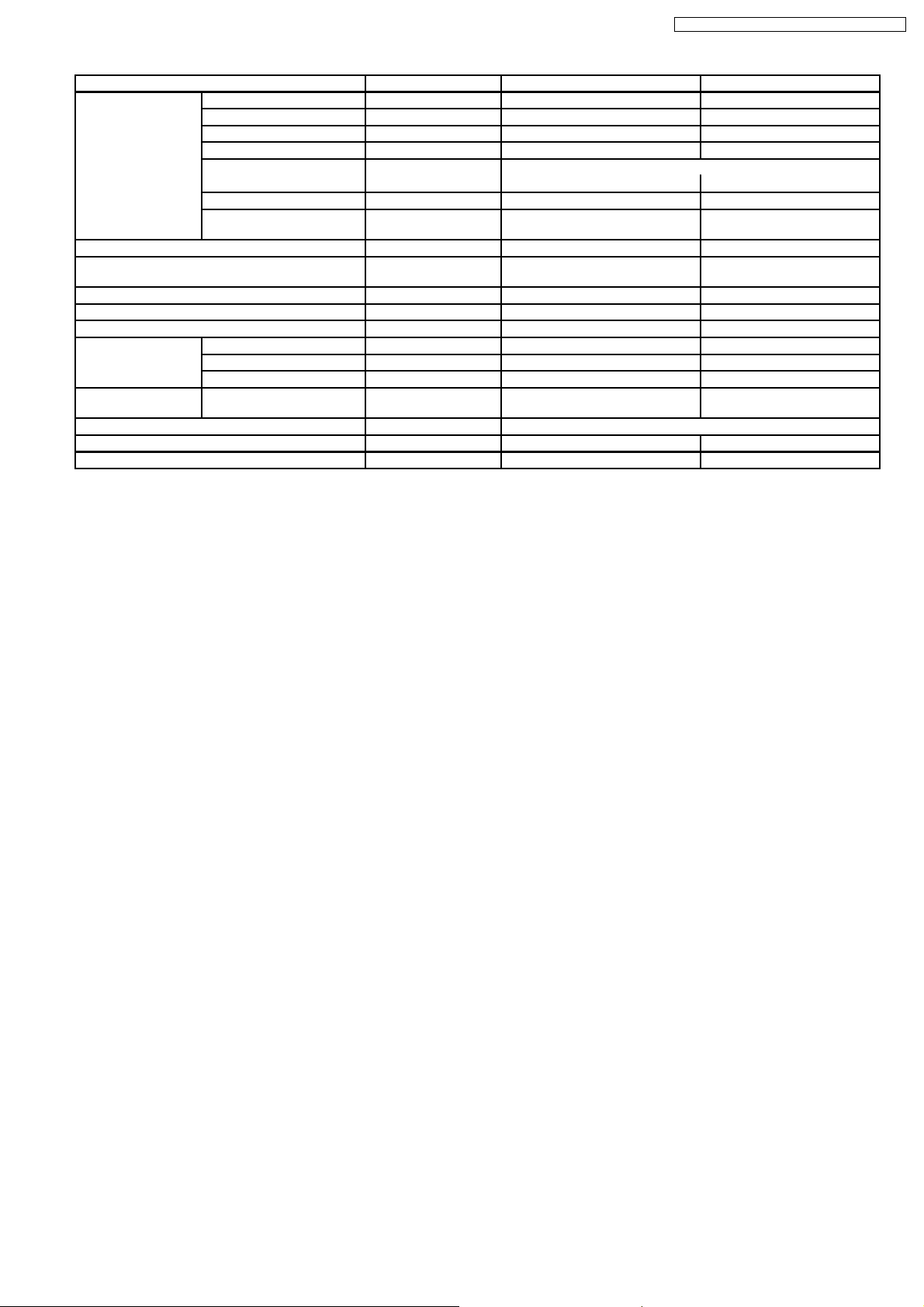
3 Product Specifications
3.1. CS-A18DKD CU-A18DKD
Unit CS-A18DKD CU-A18DKD
Power Source (Phase, Voltage, Cycle) ,V,Hz Single, 220 - 230, 50
Cooling Capacity kW (BTU/h) 5.30 (18,10 0) - 5.30 (18,100)
Heating Capacity kW (BTU/h) 5.65 (19,300) - 5.70 (19,400)
Moisture Removal l/h (Pint/h) 2.9 (6.1)
Airflow Method OUTLET
INTAKE
Air Volume Lo m3/min (cfm) Cooling; 13.1 (460) - 13.1 (460) 28.6 (1,010) - 31.1 (1,100)
Heating; 14.2 (500) - 14.2 (500)
Me m3/min (cfm) Cooling; 14.5 (510) - 14.5 (510) —
Heating; 14.7 (520) - 14.7 (520)
Hi m3/min (cfm) Cooling; 15.3 (540) - 15.3 (540) 50.7 (1,790) - 52.7 (1,860)
Heating; 16.0 (560) - 16.0 (560)
SHi m3/min (cfm) Cooling; 16.0 (560) - 16.0 (560) —
Noise Level dB (A) Cooling; High 43 - 43, Low 38 -38 Cooling; High 53 - 54
Heating; High 42 - 42, Low 38 -38 Heating; High 54 - 55
Electrical Data Input Power kW Cooling; 1.72 - 1.76
Running Current A Cooling; 8.0 - 7.8
EER W/W (BTU/hW) Cooling; 3.08 - 3.01 (10.52 - 10.28)
COP W/W (BTU/hW) Heating; 3.42 - 3.33 (11.70 - 11.35)
Starting Current A 44.5
Piping Conne ction Port
(Flare piping)
Pipe Size
(Flare piping)
Drain
Hose
Power Cord Length m 1.9 —
Dimensions Height inch (mm) 10 - 13/16 (275) 29 - 17/32 (750)
Net Weight lb (kg) 24 (11.0) 132 (60.0)
Compressor Description — Rotary (1 cylinder)
Inner diame ter mm 12 —
Length mm 650 —
Number of core-wire 3 (1.5 mm2) —
Width inch (mm) 39 - 9/32 (998) 34 - 7/16 (875)
Depth inch (mm) 9 - 1/16 (230) 13 - 19/32 (345)
Motor Type — Induction (2-poles)
Rated Output kW — 1.5
inch
inch
inch
inch
SIDE VIEW TOP VIEW
Heating; 1.65 - 1.71
Heating; 7.7 - 7.6
G ; Half Union 1/2”
L ; Half Union 1/4”
G ; (gas side) 1/2”
L ; (liquid side) 1/4”
G ; 3-way valve 1/2”
L ; 3-way valve 1/4”
G ; (gas side) 1/2”
L ; (liquid side) 1/4”
rolling piston type
6
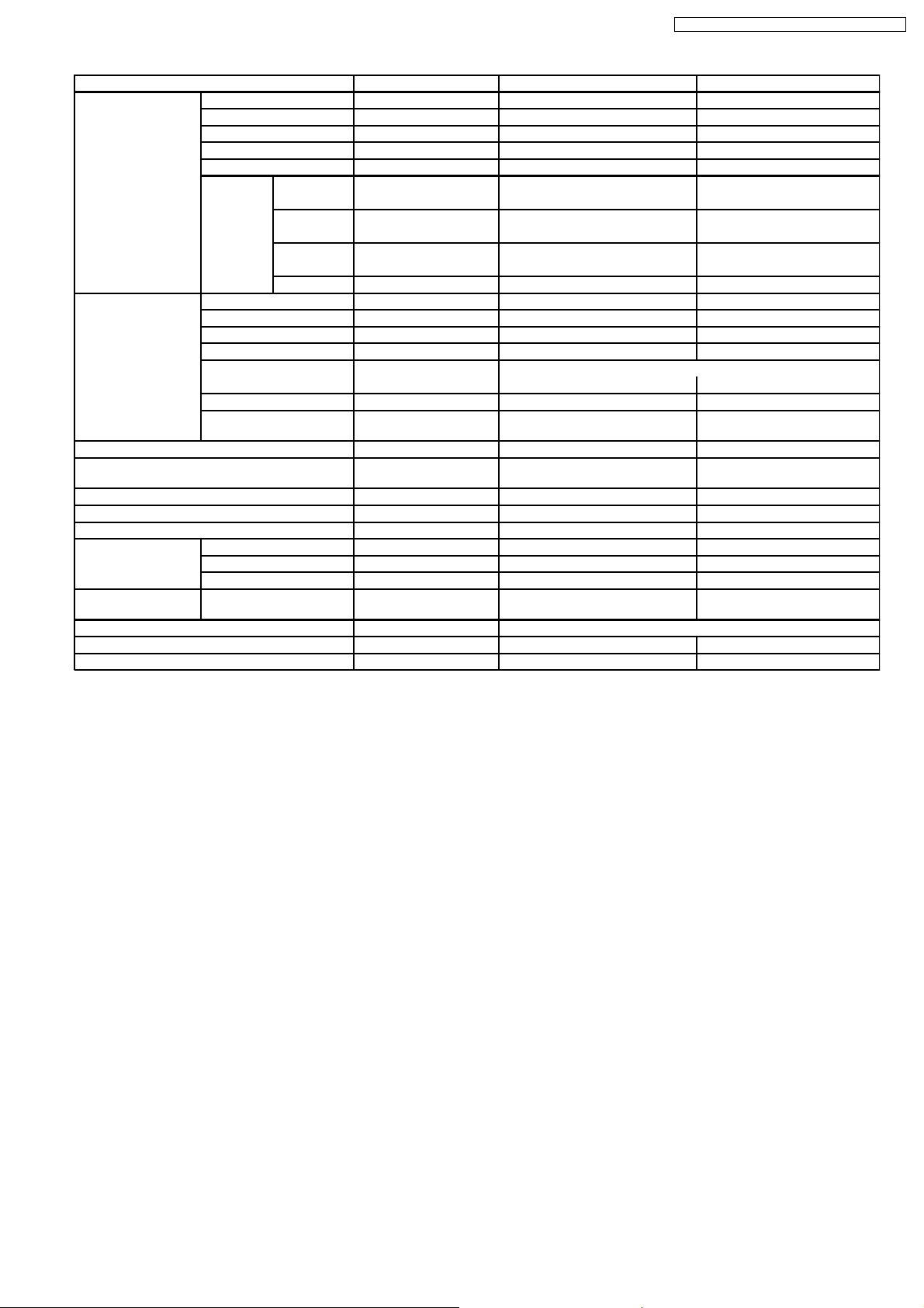
CS-A18DKD CU-A18DKD / CS-A24DKD CU-A24DKD
Unit CS-A18DKD CU-A18DKD
Air Circulation Description Cross-flow Fan Propeller Fan
Material ASHT-18 PP
Motor Type Transistor (8-poles) Induction (6-poles)
Input W 50.0 - 50.0 150.3 - 150.3
Rated Output W 30 80
Fan Speed Low rpm Cooling; 1,160 - 1,160 460 - 490
Heating; 1,240 - 1,240
Medium rpm Cooling; 1,290 - 1,290 —
Heating; 1,290 - 1,290
High rpm Cooling; 1,360 - 1,360 815 - 830
Heating; 1,400 - 1,400
SuperHigh rpm Cooling; 1,400 - 1,400 —
Heat Exchanger Description Evaporator Condenser
Tube material Copper Copper
Fin material Aluminium (Pre Coat) Aluminium
Fin Type Slit Fin Corrugated Fin
Row / Stage (Plate fin configuration, forced draft)
2×15 2×28
FPI 21 16
Size (W × H × L) mm 810 × 315 × 25.4 827.7
Refrigerant Control Device — Capillary Tube
Refrigeration Oil (cm3) — SUNISO 4GDID or ATMOS
Refrigerant (R-22) g (oz) — 1,710 (60.4)
Thermostat — —
Protection Device — Inner Protector
Capillary Tube Length mm — Cooling; 970, Heating; 820
Flow Rate l/min — Cooling; 11.0, Heating; 27.0
Inner Diameter mm — Cooling; 1.6, Heating; 2.2
Air Filter Material
Style
Capacity Control Capillary Tube
Compressor Capacitor µF, VAC — 45 µF, 400/440VAC
Fan Motor Capacitor µF, VAC — 3.5 µF, 440VAC
P.P.
Honeycomb
× 711.2 × 44
862.2
M60 or ATMOS 56M
—
Note:
• Specifications are subject to change without notice for further improvement.
7
CS-A18DKD CU-A18DKD / CS-A24DKD CU-A24DKD
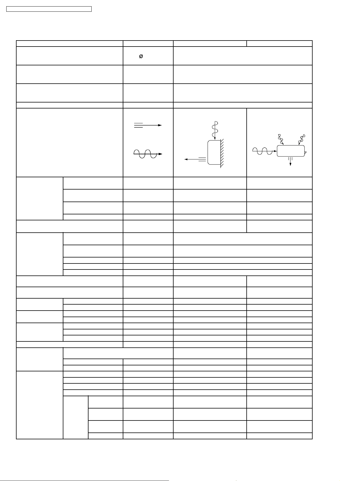
3.2. CS-A24DKD CU-A24DKD
Unit CS-A24DKD CU-A24DKD
Power Source (Phase, Voltage, Cycle) ,V,Hz Single, 220 - 230, 50
Cooling Capacity kW (BTU/h) 7.03 - 7.03 (24,00 0 - 24,000)
Heating Capacity kW (BTU/h) 7.80 - 7.80 (26,600 - 26,600 )
Moisture Removal l/h (Pint/h) 4.0 (8.5)
Airflow Method OUTLET
INTAKE
Air Volume Lo m3/min (cfm) Cooling; 13.7 (480) - 13.7 (480) 28.1 (990) - 29.9 (1,055)
Heating; 14.7 (520) - 14.7 (520)
Me m3/min (cfm) Cooling; 15.8 (560) - 15.8 (560) —
Heating; 15.8 (560) - 15.8 (560)
Hi m3/min (cfm) Cooling; 16.8 (590) - 16.8 (590) 49.7 (1,750) - 50.7 (1,790)
Heating; 17.6 (620) - 17.6 (620)
SHi m3/min (cfm) Cooling; 17.6 (620) - 17.6 (620) —
Noise Level dB (A) Cooling; High 47 - 47, Low 41 - 41 Cooling; High 53 - 54
Heating; High 46 - 46, Low 41 - 41 Heating; High 54 - 55
Electrical Data Input Power kW Cooling; 2.54 - 2.58
Running Current A Cooling; 12.3 - 12.2
EER W/W (BTU/hW) Cooling; 2.77 - 2.72 (9.45 - 9.30)
COP W/W (BTU/hW) Heating; 3.08 - 3.05 (10.51 - 10.39)
Starting Current A 65.0
Piping Conne ction Port
(Flare piping)
Pipe Size
(Flare piping)
Drain
Hose
Power Cord Length m 1.9 —
Dimensions Height inch (mm) 10 - 13/16 (275) 29 - 17/32 (750)
Net Weight lb (kg) 26 (12.0) 139 (63.0)
Compressor Description — Rotary (1 cylinder) rolling
Air Circulation Description Cross-flow Fan Propeller Fan
Inner diame ter mm 12 —
Length mm 650 —
Number of core-wire 3 (2.5 mm2) —
Width inch (mm) 39 - 9/32 (998) 34 - 7/16 (875)
Depth inch (mm) 9-1/16 (230) 13 - 19/32 (345)
Motor Type — Induction (2-poles)
Rated Output kW — 2.0
Material ASHT-18 PP
Motor Type Transistor (8-poles) Induction (6-poles)
Rated Output W 30 80
Fan Speed Low rpm Cooling; 1,280 - 1,280 460 - 490
Medium rpm Cooling; 1,480 - 1,480 —
High rpm Cooling; 1,570 - 1,570 815 - 830
SuperHigh rpm Cooling; 1,650 - 1,650 —
inch
inch
inch
inch
SIDE VIEW TOP VIEW
Heating; 2.53 - 2.56
Heating; 12.2 - 12.1
G ; Half Union 5/8”
L ; Half Union 1/4”
G ; (gas side) 5/8”
L ; (liquid side) 1/4”
Heating; 1,380 - 1,380
Heating; 1,480 - 1,480
Heating; 1,650 - 1,650
G ; 3-way valve 5/8”
L ; 3-way valve 1/4”
G ; (gas side) 5/8”
L ; (liquid side) 1/4”
piston type
8
CS-A18DKD CU-A18DKD / CS-A24DKD CU-A24DKD
Unit CS-A24DKD CU-A24DKD
Heat Exchanger Description Evaporator Condenser
Tube material Copper Copper
Fin material Aluminium (Pre Coat) Aluminium
Fin Type Slit Fin Corrugated Fin
Row / Stage (Plate fin configuration, forced draft)
2×15 2×28
FPI 21 18
Size (W × H × L) mm 810 × 315 × 25.4 827.7
Refrigerant Control Device — Capillary Tube
Refrigeration Oil (cm3) — SUNISO 4GDID or ATMOS
Refrigerant (R-22) g (oz) — 2,050 (72.4)
Thermostat — —
Protection Device — Inner Protector
Capillary Tube Length mm — Cooling; 730, Heating; 340
Flow Rate l/min — Cooling; 12.5, Heating; 21.0
Inner Diameter mm — Cooling; 1.6, Heating; 2.0
Air Filter Material
Style
Capacity Control Capillary Tube
Compressor Capacitor µF, VAC — 45 µF, 400/440VAC
Fan Motor Capacitor µF, VAC — 3.5 µF, 440VAC
P.P.
Honeycomb
× 711.2 × 44.0
862.2
M60 or ATMOS 56M
—
Note:
• Specifications are subject to change without notice for further improvement.
9
CS-A18DKD CU-A18DKD / CS-A24DKD CU-A24DKD
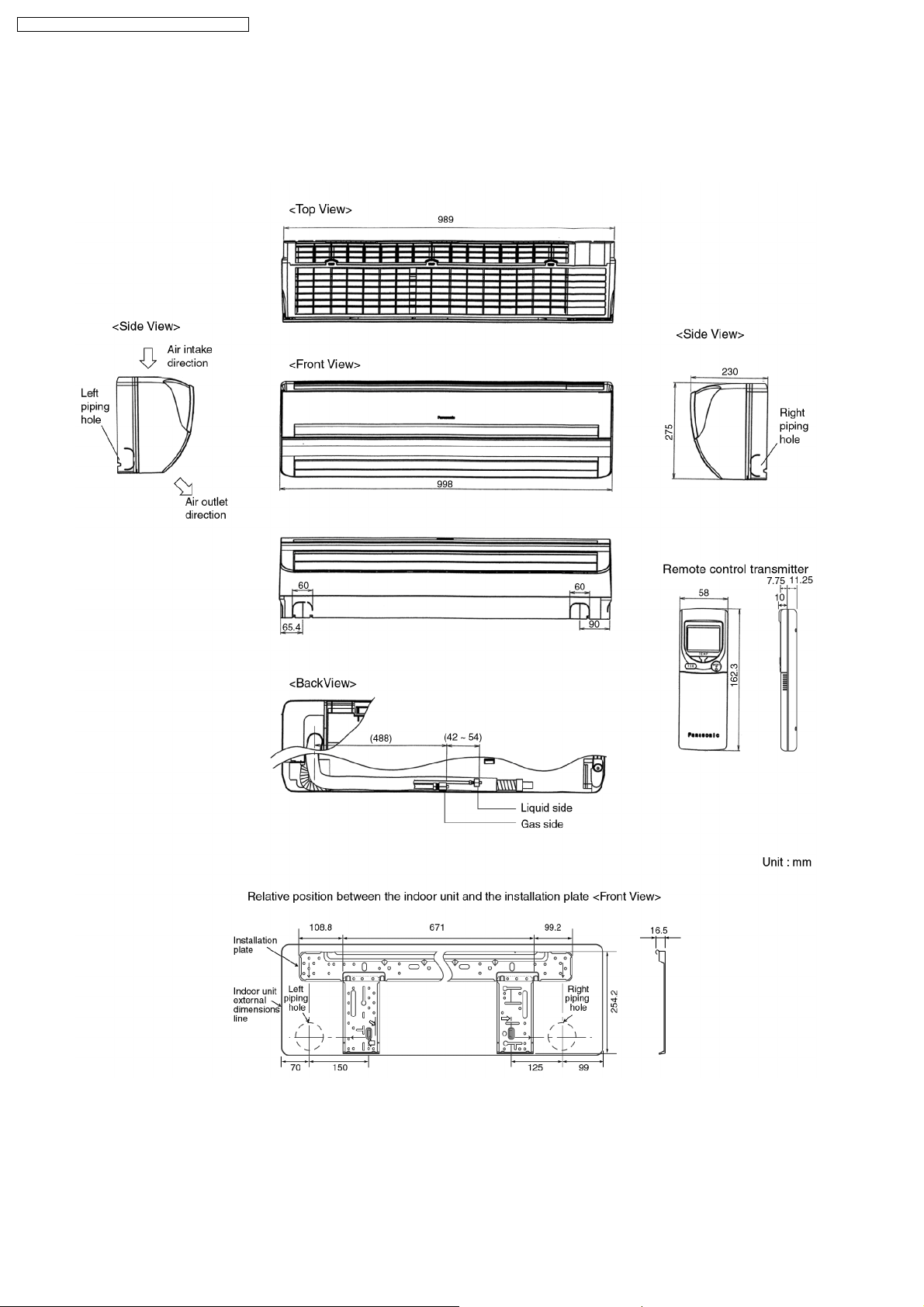
4 Dimensions
4.1. Indoor Unit & Remote Control
4.1.1. CS-A18DKD CS-A24DKD
10
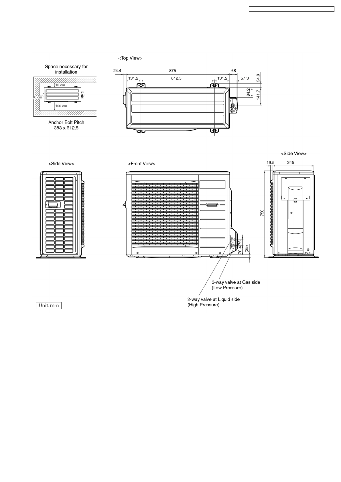
4.2. Outdoor Unit
4.2.1. CU-A18DKD CU-A24DKD
CS-A18DKD CU-A18DKD / CS-A24DKD CU-A24DKD
11
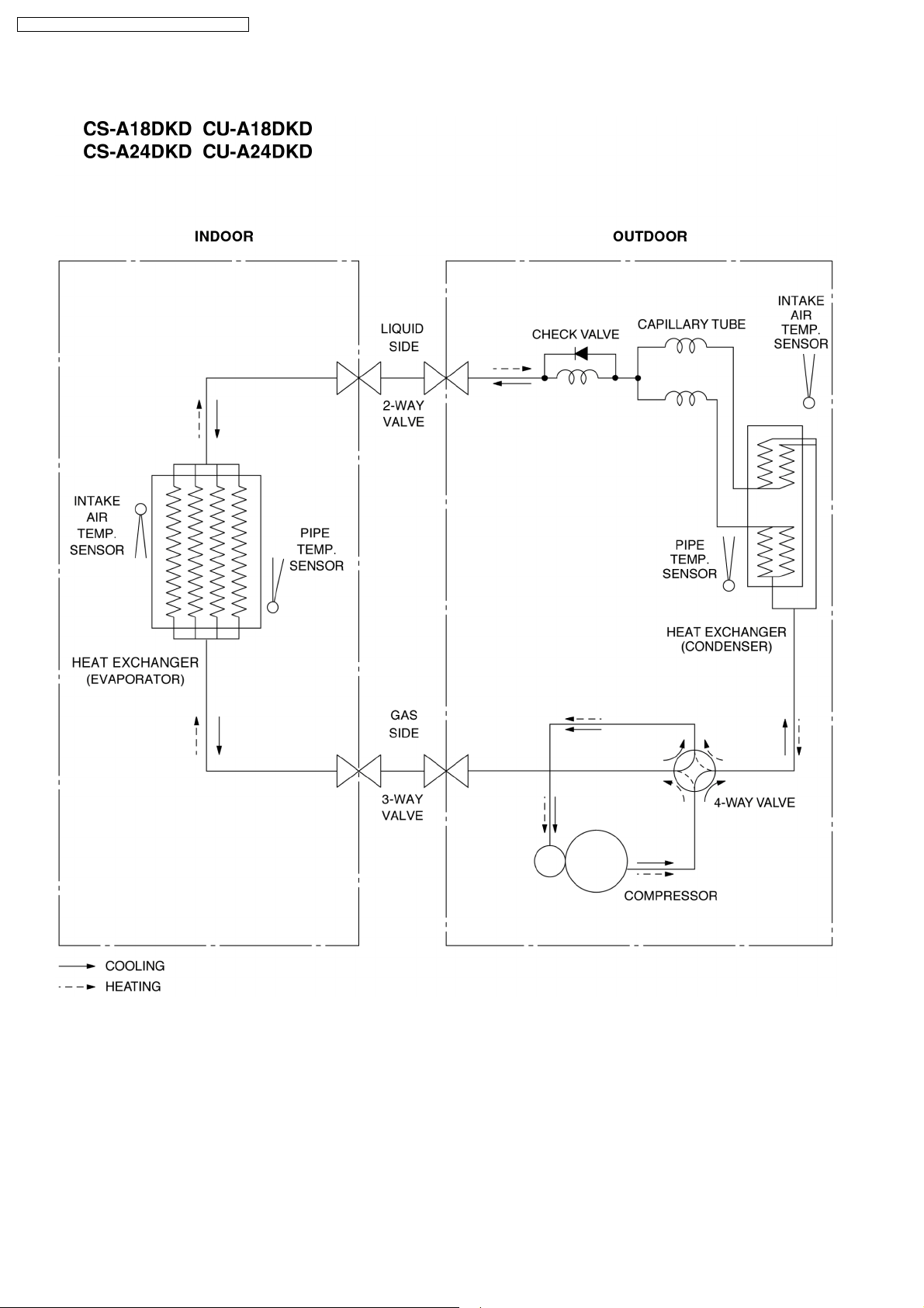
CS-A18DKD CU-A18DKD / CS-A24DKD CU-A24DKD
5 Refrigeration Cycle Diagram
12
6 Block Diagram
CS-A18DKD CU-A18DKD / CS-A24DKD CU-A24DKD
13
CS-A18DKD CU-A18DKD / CS-A24DKD CU-A24DKD
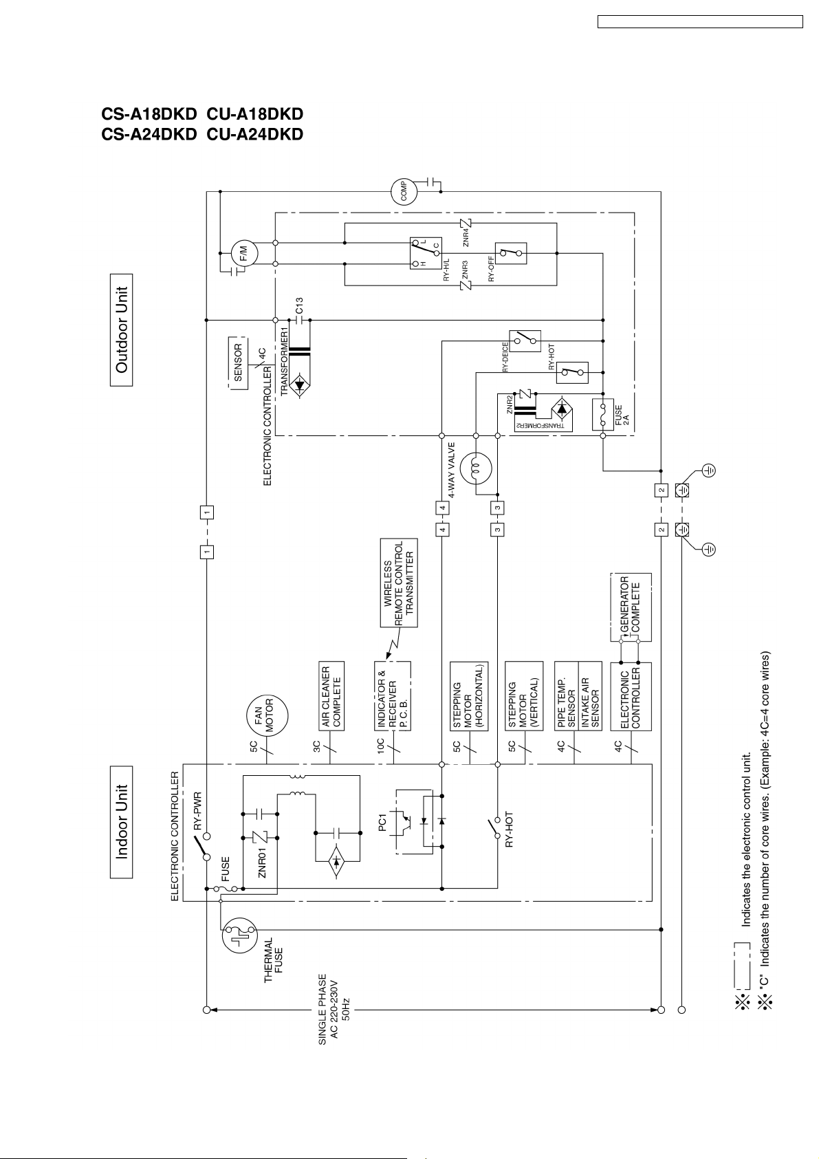
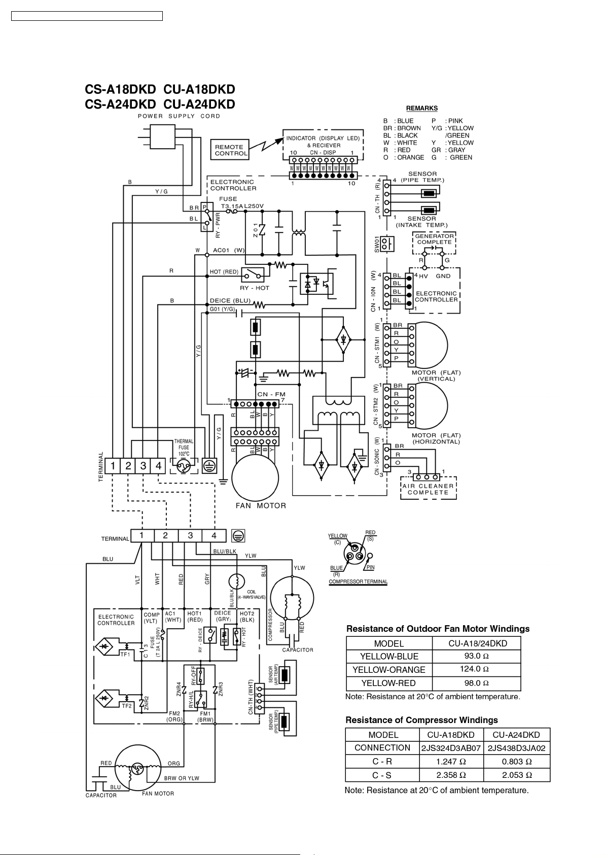
7 Wiring Diagram
14
CS-A18DKD CU-A18DKD / CS-A24DKD CU-A24DKD
8 Operation Details
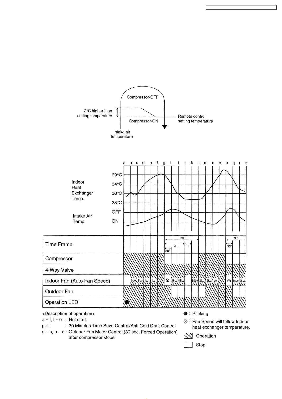
8.1. Heating Operation
• Heating operation can be set using remote control.
• This operation is applied to warm the room temperature reaches the setting temperature set on the remote control.
• The remote control setting temperature, which takes the reading of intake air temperature sensor, can be adjusted from 16°C
to 30°C.
• During Heating operation, the compressor will stop running and restart as shown in below figure.
8.1.1. Heating Operation Time Diagram
15
CS-A18DKD CU-A18DKD / CS-A24DKD CU-A24DKD
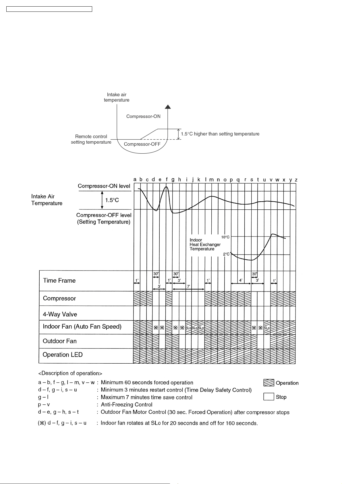
8.2. Cooling Operation
• Cooling operation can be set using remote control.
• This operation is applied to cool down the room temperature reaches the setting temperature set on the remote control.
• The remote control setting temperature, which takes the reading of intake air temperature sensor, can be adjusted from 16°C
to 30°C.
• During cooling operation, the compressor will stop running and restart as shown in below figure.
8.2.1. Cooling Operation Time Diagram
16
CS-A18DKD CU-A18DKD / CS-A24DKD CU-A24DKD
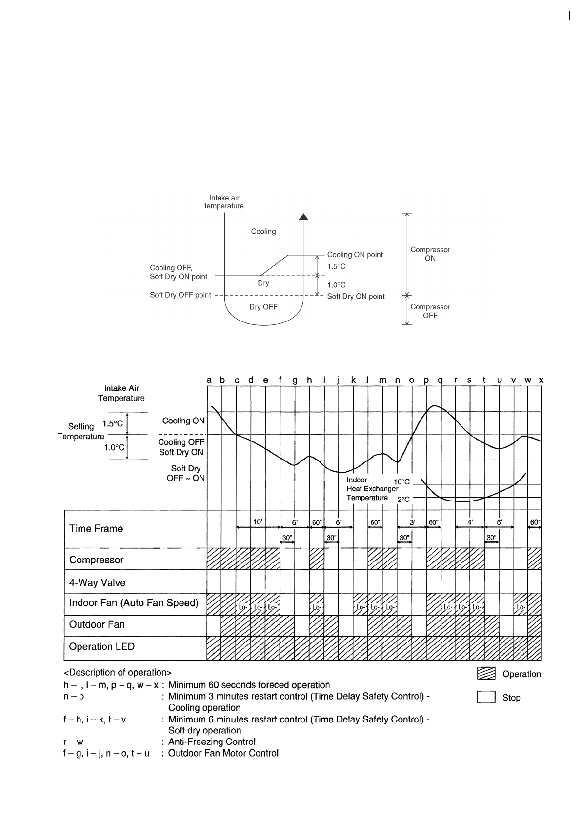
8.3. Soft Dry Operation
• Soft Dry operation can be set using remote control.
• Soft Dry operation is applied to dehumidify and to perform a gentle cooling to the room.
• This operation starts when the intake air temperature sensor reaches the setting temperature on the remote control.
• When operation begins, Soft Dry will be switched “ON” for a maximum 10 minutes, then Soft Dry operation will be turned “OFF”
for a minimum 6 minutes. After that, the Soft Dry operation will be “ON” and “OFF” based on the setting temperature as shown
in below figure.
• However after 3 minutes of compressor off, during Soft Dry “OFF” (within 6 minutes Soft Dry restart control), the indoor unit will
start to operate at normal Cooling mode if the intake temperature is higher than Cooling “ON” point.
8.3.1. Soft Dry Operation Time Diagram
17
CS-A18DKD CU-A18DKD / CS-A24DKD CU-A24DKD
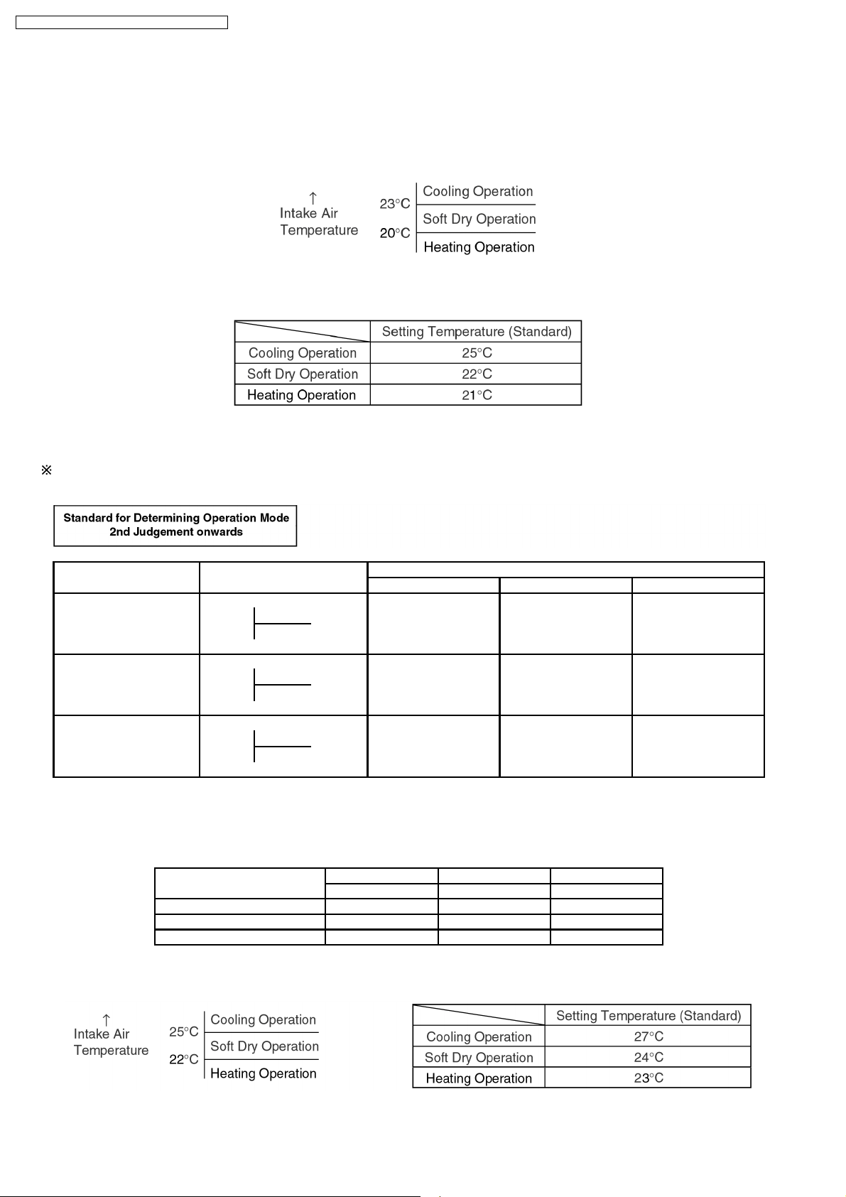
8.4. Automatic Operation
• Automatic operation can be set using remote control.
• This operation starts to operate with indoor fan at SLo speed for 25 seconds to judge the intake air temperature.
• After judged the temperature, the operation mode is determined by refering to the below standard.
• Then, the unit start to operate at determined operation mode, until it is switched off using remote control, with the setting
temperature as shown in below table.
• Operation mode will be determine again for judgement after 1 hour of operation, if the room temperature reaches to set
temperature and compressor off time is over 7 minutes 30 seconds continuously.
The present mode will be continued, if the room temperature does not reach to set temperature (Compressor keeps running) eventhrough after
1 hour from automatic operation mode started.
Present Judgement Next Mode
Mode Cooling Soft Dry Heating
O O
Cooling 23°C Cooling (Judgement: Not Applicable (Judgement:
Heating 23°C & Above) Below 23°C)
O O
Soft Dry 20°C Soft Dry Not Applicable (Judgement: (Judgement:
Heating 20°C & Above) Below 20°C)
O O
Heating Cooling (Judgement: Not Applicable (Judgement:
25°C Heating 25°C & Above) Below 25°C)
• Automatic Set Temperature
For each operation, set temperature will automaticlly set as shown below.
• The setting temperature for all the operations can be changed one level up or one level down from the standard temperature
as shown in below table by pressing on the temperature up or temperature down button at remote control.
Operation Hi (Standard) Lo
(+2°C) (±0°C) (-2°C)
Cooling 27°C 25°C 23°C
Soft Dry 24°C 22°C 20°C
Heating 23°C 21°C 19°C
• The operation mode judging temperature and standard setting temperature can be increased by 2°C permanently, by open the
circuit of JX1 at indoor electronic controller.
18
CS-A18DKD CU-A18DKD / CS-A24DKD CU-A24DKD
8.5. Operation Control
8.5.1. Restart Control (Time Delay Safety Control)
• When the thermo-off temperature (temperature which compressor stops to operate) is reached during:-
− Cooling/Heating operation - the compressor stops for 3 minutes (minimum) before resume operation.
− Soft Dry operation - the compressor stops for 6 minutes (minimum) before resume operation.
• If the operation is stopped by the remote control, the compressor will not turn on within 3 minutes from the moment operation
stop, although the unit is turn on again within the period.
• This phenomenon is to balance the pressure inside the refrigerant cycle.
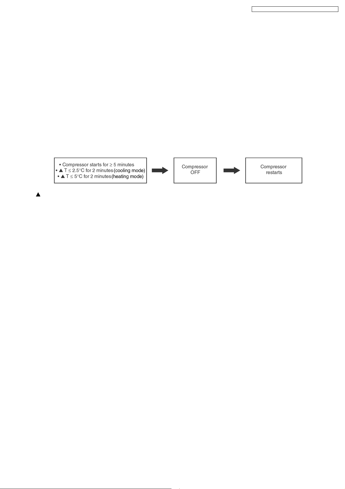
8.5.2. Compressor Reverse Rotation Protection Control
• If the compressor is operating continuously for 5 minutes or longer and the temperature difference between intake air and
indoor heat exchanger is 2.5°C (cooling mode)/5°C (heating mode) or less for continuous 2 minutes, compressor will stop and
restart automatically.
• Time Delay Safety Control is activated before the compressor restart.
T = Intake air temperature - Indoor heat exchanger temperature
• This is to prevent compressor from rotate reversely when there is an instantaneous power failure.
19
CS-A18DKD CU-A18DKD / CS-A24DKD CU-A24DKD
(For 8.5.3. to 8.5.7. information applies only to Cooling and Soft Dry Operation)
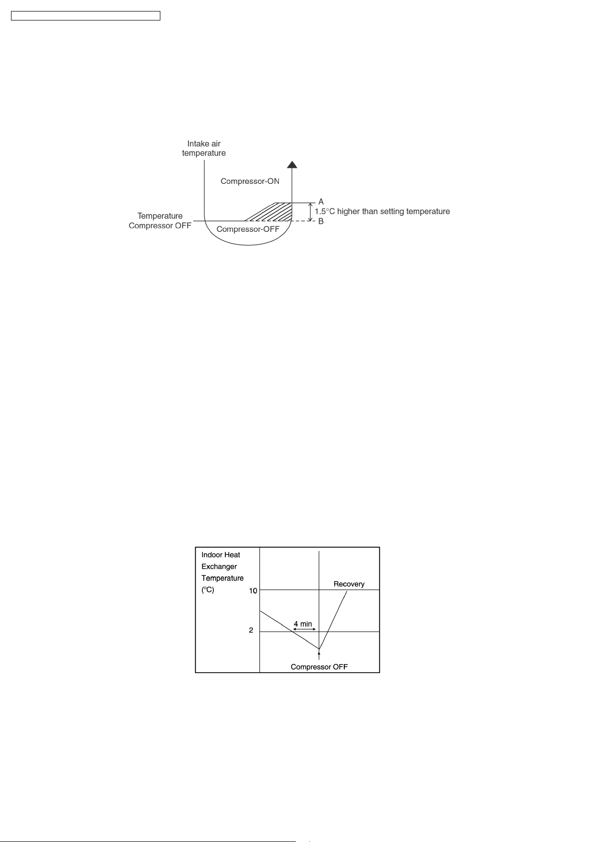
8.5.3. 7 Minutes Time Save Control
• The compressor will start automatically if it has stopped for 7 minutes and the intake air temperature falls between the
compressor ON temperature (A) and compressor OFF temperature (B) during the period.
• This phenomenon is to reduce the built up humidity inside a room.
8.5.4. 60 Seconds Forced Operation
• Once the air conditioner is turned on, the compressor will not stop within 60 seconds in a normal operation although the intake
air temperature has reached the thermo-off temperature. However, force stop by pressing the OFF/ON operation button at the
remote control is permitted.
• The reason for the compressor to force operate at minimum 60 seconds is to allow the refrigerant oil run in a full cycle and
return back to the outdoor unit.
8.5.5. Starting Current Control
• When the compressor, outdoor fan motor and indoor fan motor are simultaneously started, the indoor fan motor will start to
operate at 1.6 second later.
• The reason of the difference is to reduce the starting current flow.
8.5.6. Anti-Freezing Control
• If the temperature of the indoor heat exchanger falls below 2°C continuously for 4 minutes or more, the compressor turns off.
The fan speed setting remains the same.
• This phenomenon is to protect the indoor heat exchanger from freezing and to prevent higher volume of refrigerant in liquid form
returning to the compressor.
• Compressor will restart again when the indoor heat exchanger temperature rises to 10°C (Recovery).
• Restart control (Time Delay Safety Control) will be applied in this Control if the recovery time is too short.
20
CS-A18DKD CU-A18DKD / CS-A24DKD CU-A24DKD
8.5.7. Anti-Dew Formation Control
• Purpose is to prevent dew formation on indoor unit air discharge area.
• When room temperature is constant (±1°C) the following conditions occur for 30 minutes continuously, anti-dew formation will
activate:
− Remote Control setting temperature is less than 25°C.
− Compressor is on.
− Cooling operation mode.
− Indoor Fan motor operate at Low fan speed or QLo.
• This control is cancelled immediately when above condition is changed.
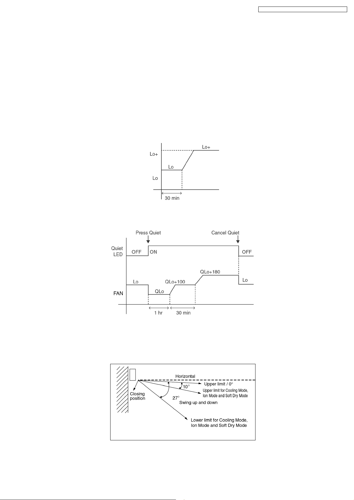
• Anti-Dew formation is control by:
1. Increasing Air Flow Volume
a. Lo fan speed
Lo fan speed is changed to Lo+ after 30 min to prevent dew formation.
b. QLo fan speed
Dew formation may occurs at QLo cool, therefore QLo cool is operated only 1 hr 30 min (1 hr QLo, 30 min QLo +100
rpm). After that, it operates at QLo +180rpm (However Quiet LED remains on).
2. Norrowing
Vertical Airflow Direction
− During Anti-dew condensation prevention, Airflow Direction Auto-control angle change from 10° - 38° to 10° - 27° under
Cooling and Soft Dry operation mode.
21
CS-A18DKD CU-A18DKD / CS-A24DKD CU-A24DKD
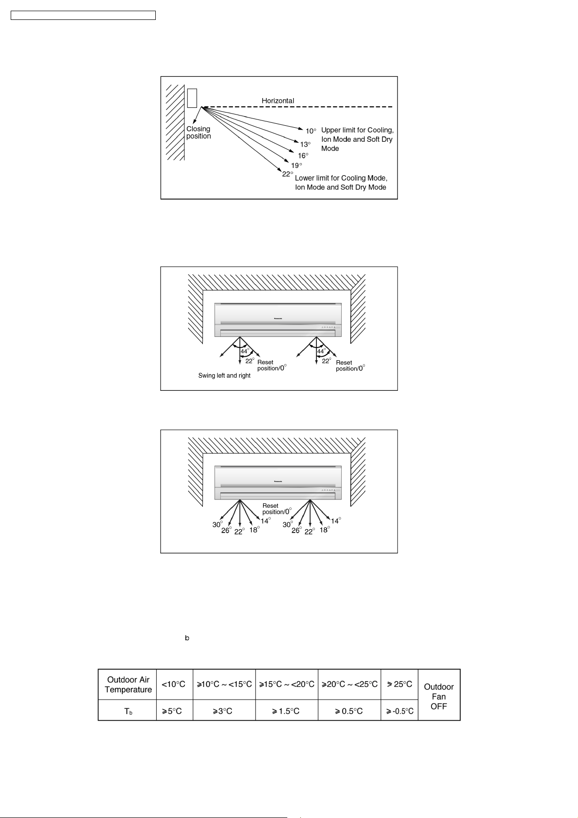
− During Anti-dew condensation prevention, Airflow Direction Manual control angle change from 10°, 14°, 18°, 22°, 27° to
10°, 13°, 16°, 19°, 22° under Cooling and Soft Dry operation mode.
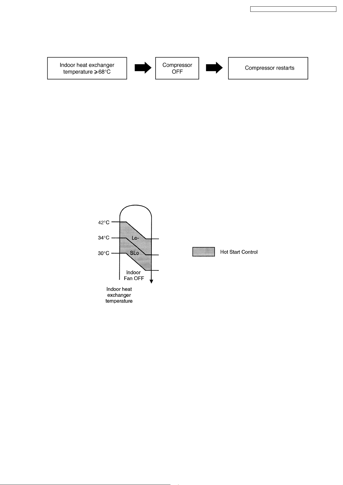
3. Narrowing
Horizontal Airflow Direction
− During Anti-dew condensation prevention, Airflow Direction Auto-control angle change from 0° - 44° to 14° - 30° under
Cooling and Soft Dry operation mode.
− During Anti-dew condensation prevention, Airflow Direction Manual control angle change from 0°, 11°, 22°, 33°, 44° to
14°, 18°, 22°, 26°, 30° under Cooling and Soft Dry operation mode.
(For 8.5.8. to 8.5.13. information applies only to Heating Operation)
8.5.8. Overload Protection Control
• Outdoor Fan Control
− If the temperature of the Outdoor Heat Exchanger less than -3°C, Outdoor Fan is ON. The Outdoor Fan stop, when Outdoor
Heat Exchanger temperature is T
The Outdoor Fan restarts when the indoor heat exchanger temperature falls to 49°C.
or more according to Outdoor Air Temperature region as table below:
− During starting of Heating mode and after deice, Outdoor Fan ON for 90 sec. (Hi).
22
CS-A18DKD CU-A18DKD / CS-A24DKD CU-A24DKD
• Compressor high pressure protection
− If the indoor heat exchanger becomes 68°C or more, the compressor will stop and restart automatically.
− Time Delay Safety Control is activated before the compressor restart.
8.5.9. 4-Way Valve Control
• 4-way valve always on during Heating operation. (except deicing operation)
• When the unit is switched off by remote control during Heating operation, the 4-way valve stay at Heating position for 5 minutes.
• This is to prevent the refrigerant flow process sound for being occur.
8.5.10. Outdoor Fan Motor Control
• When compressor stops (reaches room temperature), outdoor fan will operate for 30 seconds (forced operation).
• This is to release the heat and to obtain the lowest pressure as fast as possible.
8.5.11. Hot Start Control
• Hot Start Control is to prevent cool air discharge into the room when heating operation start.
• When Heating operation starts, Indoor fan will not start until the indoor heat exchanger reaches 30°C as diagram shown.
• Hot start is completed when indoor heat exchanger rises to 42°C or operation over 4 minutes.
23
CS-A18DKD CU-A18DKD / CS-A24DKD CU-A24DKD
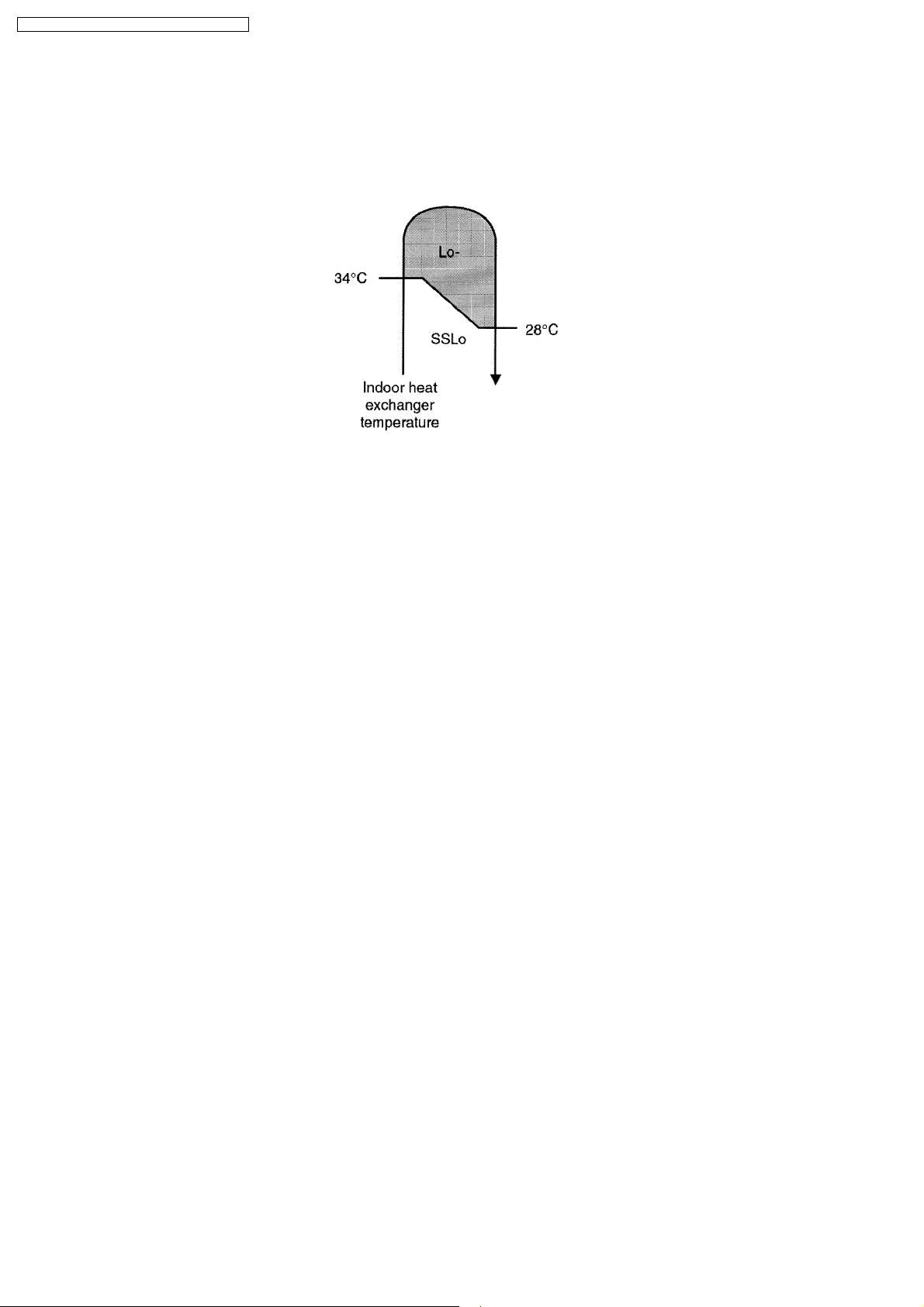
8.5.12. Anti Cold Draft Control
• This operation is to prevent the Cold Draft during Heating mode operation.
• The operation will start when compressor OFF (Thermo OFF) during Heating operation.
• For the first 30 sec. from compressor OFF (Termo OFF), Indoor fan speed will operate accordingly to the Indoor heat exchanger
temperature as shown below:
• After 30 sec. from compressor OFF (thermo OFF), Indoor fan will run at SSLo speed only.
• Anti Cold Draft Control will stop when:
− Intake temperature < set temperature. (Time Delay Safety Control 4 minutes waiting is valid)
− 30 Minutes Time Save Control activates.
8.5.13. Deicing Control
Deice starts to prevent frosting at outdoor heat exchanger.
• Normal Deicing
Deice operations detection commences after 60 minutes of Heating operation starts or 60 minutes after previous deice
operation. If the TRS (Thermal Read Switch) senses the outdoor piping temperature drops to -4°C (TRS CLOSE) or less for 50
sec. continuously during compressor is in operation, deice will start.
(There is no detection during Outdoor Fan stops.)
• Overload Deicing
During heating operation, if the outdoor Fan OFF duration (due to overload control) is accumulated up to 60 minutes and after
compressor starts for 1 minutes, deicing starts.
• Deicing ends when
1. 12 minutes after deicing operation starts;
2. The outdoor piping temperature rises to 12°C.
• After deicing operation, compressor stops for 30 seconds and 4-way valve stays at cooling position for 10 seconds.
24
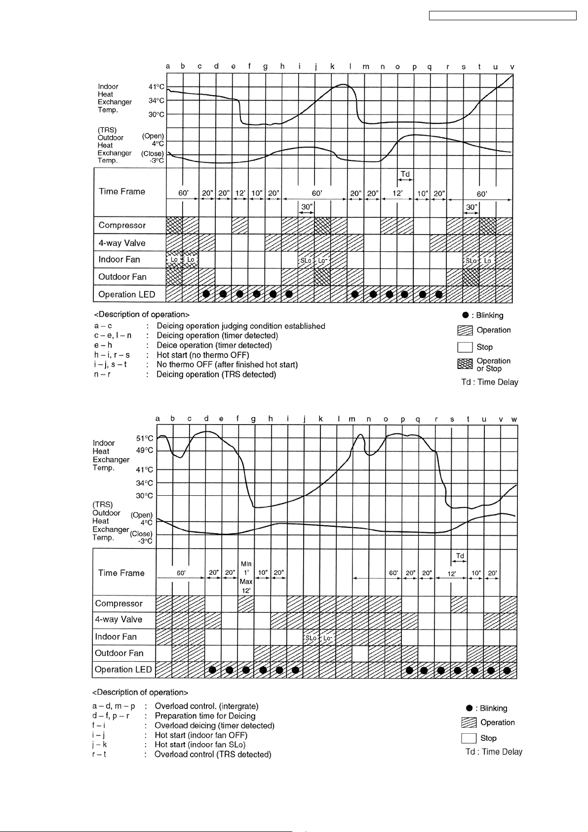
Normal Deicing Time Diagram
CS-A18DKD CU-A18DKD / CS-A24DKD CU-A24DKD
Overload Deicing Time Diagram
25
CS-A18DKD CU-A18DKD / CS-A24DKD CU-A24DKD
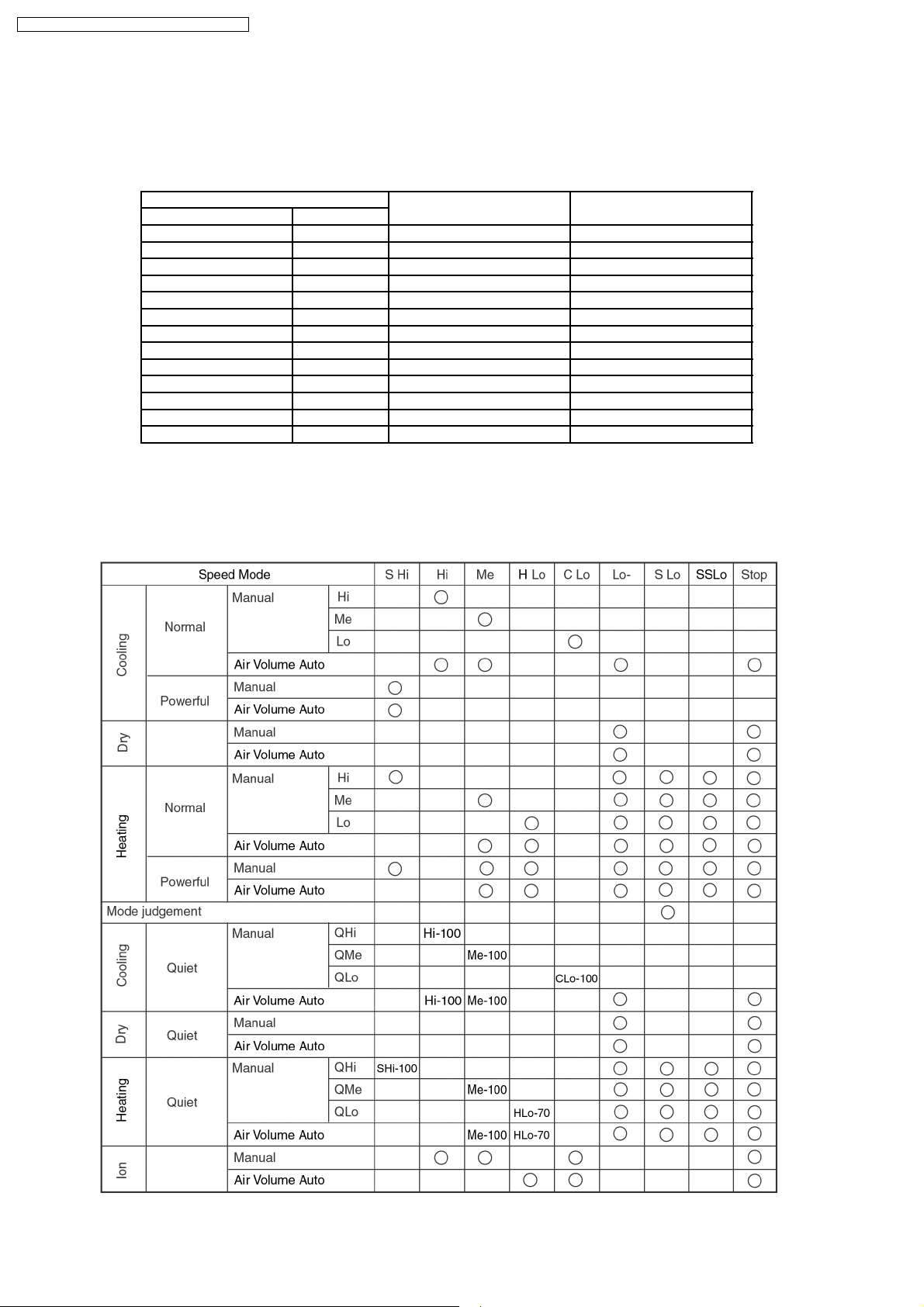
8.6. Indoor Fan Speed Control
• Indoor Fan Speed can be set using remote control.
8.6.1. Fan Speed Rotation Chart
Fan Speed CS-A18DKD CS-A24DKD
Cool, Dry Heat
SHi Hi 1460 1650
Hi - 1400 1590
Me Me 1320 1480
Lo+ Lo 1270 1380
Lo - 1190 1280
Lo- Lo- 980 1070
SLo SLo 760 830
- SSLo 300 300
QSHi QHi 1360 1550
QHi - 1300 1490
QMe QMe 1220 1380
- QLo 1170 1280
QLo - 1090 1180
8.6.2. Automatic Fan Speed Control
• When set to Auto Fan Speed, the fan speed is adjusted between maximum and minimum setting as shown in the table.
− Fan speed rotates in the range of Hi and Me.
− Deodorizing Control will be activated.
26
 Loading...