

Page 1
Operating Instructions
Register now!!
This product is eligible for
the AVCCAM 3 Year
Warranty Repair Program.
For details, see page 6.
http://panasonic.biz/sav/pass_e/
Memory Card Camera-Recorder
Model No. AG-HMC80P
Vol.1
Volume
Note that Operation Instructions Vol.1 describes basic operations
of the Memory Card Camera-Recorder.
For instructions on advanced operations of the Memory Card
Camera-Recorder, refer to Operating Instructions Vol.2 (pdf file)
contained in the supplied CD-ROM.
1
Before operating this product, please read the instructions carefully and save this manual for
future use.
SS0710TU5053 -PS
Printed in Japan
ENGLISH
VQT2Y43-3
Page 2

CAUTION
RISK OF ELECTRIC SHOCK
DO NOT OPEN
Read this first!
CAUTION: TO REDUCE THE RISK OF ELECTRIC
SHOCK, DO NOT REMOVE COVER (OR BACK).
NO USER-SERVICEABLE PARTS INSIDE.
REFER TO SERVICING TO QUALIFIED SERVICE
PERSONNEL.
The lightning flash with arrowhead symbol,
within an equilateral triangle, is intended to
alert the user to the presence of uninsulated
“dangerous voltage” within the product’s
enclosure that may be of sufficient magnitude
to constitute a risk of electric shock to persons.
The exclamation point within an equilateral
triangle is intended to alert the user to
the presence of important operating and
maintenance (servicing) instructions in the
literature accompanying the appliance.
WARNING:
To reduce the risk of fire or electric shock,
•
do not expose this equipment to rain or
moisture.
To reduce the risk of fire or electric shock
•
hazard, keep this equipment away from all
liquids. Use and store only in locations which
are not exposed to the risk of dripping or
splashing liquids, and do not place any liquid
containers on top of the equipment.
WARNING:
Always keep memory cards (optional
accessory) or accessories (coin battery, XLR
audio adaptor cap) out of the reach of babies
and small children.
CAUTION:
To reduce the risk of fire or electric shock and
annoying interference, use the recommended
accessories only.
CAUTION:
Do not jar, swing, or shake the unit by its
handle while the conversion lens or another
accessory is attached.
Due to the added weight of the conversion
lens, any strong jolt to the handle may
damage the unit or result in personal injury.
CAUTION:
This apparatus can be operated at a voltage in
the range of 100-240 V AC.
Voltages other than 120 V are not intended for
U.S.A. and Canada.
Operation at a voltage other than 120 V
AC may require the use of a different AC
plug. Please contact either a local or foreign
Panasonic authorized service center for
assistance in selecting an alternate AC plug.
indicates safety information.
CAUTION:
The mains plug of the power supply cord shall
remain readily operable.
The AC receptacle (mains socket outlet) shall be
installed near the equipment and shall be easily
accessible.
To completely disconnect this equipment from the AC
mains, disconnect the power cord plug from the AC
receptacle.
CAUTION:
Danger of explosion or fire if battery is mistreated.
•
Do not leave the battery in an automobile
•
exposed to direct sunlight for a long period
of time with doors and windows closed.
Do not disassemble the battery or dispose
•
of it in fire.
Do not store in temperatures over 60°C (140°F).
•
For Battery Pack
Use specified charger.
•
Replace only with same or specified type.
•
For Battery of Remote Controller
Replace battery with part No. CR2025 only.
•
Do not recharge the battery.
•
CAUTION:
In order to maintain adequate ventilation, do
not install or place this unit in a bookcase,
built-in cabinet or any other confined space.
To prevent risk of electric shock or fire hazard
due to overheating, ensure that curtains and any
other materials do not obstruct the ventilation.
CAUTION:
Do not lift the unit by its handle while the
tripod is attached. When the tripod is attached,
its weight will also affect the unit’s handle,
possibly causing the handle to break and
hurting the user. To carry the unit while the
tripod is attached, take hold of the tripod.
CAUTION:
Excessive sound pressure from earphones
and headphones can cause hearing loss.
CAUTION:
Do not leave the unit in direct contact with the
skin for long periods of time when in use.
Low temperature burn injuries may be suffered
if the high temperature parts of this unit are
in direct contact with the skin for long periods
of time. When using the equipment for long
periods of time, make use of the tripod.
2
Page 3

indicates safety information.
FCC NOTICE (USA)
Declaration of Conformity
Model Number: AG-HMC80P
Trade Name: Panasonic
Responsible Party: Panasonic Corporation of North America One Panasonic Way, Secaucus, NJ
Support contact: 1-800-524-1448
This device complies with Part 15 of the FCC Rules.
Operation is subject to the following two conditions:
(1) This device may not cause harmful interference, and (2) this device must accept any interference
received, including interference that may cause undesired operation.
To assure continued compliance, follow the attached installation instructions and do not make any
unauthorized modifications.
07094
CAUTION:
This equipment has been tested and found to comply with the limits for a Class B digital device,
pursuant to Part 15 of the FCC Rules. These limits are designed to provide reasonable protection
against harmful interference in a residential installation. This equipment generates, uses and can
radiate radio frequency energy and, if not installed and used in accordance with the instructions,
may cause harmful interference to radio communications. However, there is no guarantee
that interference will not occur in a particular installation. If this equipment does cause harmful
interference to radio or television reception, which can be determined by turning the equipment off
and on, the user is encouraged to try to correct the interference by one of the following measures:
Reorient or relocate the receiving antenna.
•
Increase the separation between the equipment and receiver.
•
Connect the equipment into an outlet on a circuit different from that to which the receiver is connected.
•
Consult the dealer or an experienced radio/TV technician for help.
•
The user may find the booklet “Something About Interference”
available from FCC local regional offices helpful.
FCC Warning:
To assure continued FCC emission limit compliance, follow the attached installation instructions and
the user must use only shielded interface cables when connecting to host computer or peripheral
devices. Also any unauthorized changes or modifications to this equipment could void the user's
authority to operate this device.
NOTIFICATION (Canada)
This class B digital apparatus complies with Canadian ICES-003.
A lithium ion/polymer battery that is recyclable powers the product you have purchased.
Please call 1-800-8-BATTERY for information on how to recycle this battery.
For USA-California Only
This product contains a CR Coin Cell Lithium Battery which contains Perchlorate Material – special
handling may apply.
See www.dtsc.ca.gov/hazardouswaste/perchlorate.
Note:
Camera-Recorder
The rating plate is on the underside of the camera recorder.
AC Adaptor
The rating plate is on the underside of the AC Adaptor. Disconnect the AC mains plug from the AC mains
socket when not in use.
3
Page 4
IMPORTANT SAFETY INSTRUCTIONS
Conforms to ANSI/UL Std. 60065
1) Read these instructions.
2) Keep these instructions.
3) Heed all warnings.
4) Follow all instructions.
5) Do not use this apparatus near water.
6) Clean only with dry cloth.
7) Do not block any ventilation openings. Install in accordance with the manufacturer’s instructions.
8) Do not install near any heat sources such as radiators, heat registers, stoves, or other apparatus
(including amplifiers) that produce heat.
Do not defeat the safety purpose of the polarized or grounding-type plug. A polarized plug has two
9)
blades with one wider than the other. A grounding-type plug has two blades and a third grounding prong.
The wide blade or the third prong are provided for your safety. If the provided plug does not fit into your
outlet, consult an electrician for replacement of the obsolete outlet.
10)
Protect the power cord from being walked on or pinched particularly at plugs, convenience
receptacles, and the point where they exit from the apparatus.
1) Only use attachments/accessories specified by the manufacturer.
1
12) Use only with the cart, stand, tripod, bracket, or table specified by the manufacturer,
or sold with the apparatus. When a cart is used, use caution when moving the cart/
apparatus combination to avoid injury from tip-over.
1
3) Unplug this apparatus during lightning storms or when unused for long periods of time.
14) Refer all servicing to qualified service personnel. Servicing is required when the
apparatus has been damaged in any way, such as power-supply cord or plug is
damaged, liquid has been spilled or objects have fallen into the apparatus, the apparatus has been
exposed to rain or moisture, does not operate normally, or has been dropped.
About batteries that you can use with this unit
■
(Correct as of August 2010)
The battery that can be used with this unit is VW-VBG260/VW-VBG6.
• The unit has a function for distinguishing batteries which can be used safety. The dedicated battery
(VW-VBG260/VW-VBG6) supports this function. The only batteries suitable for use with this unit
are genuine Panasonic products and batteries manufactured by other companies and certified by
Panasonic. (Batteries which do not support this function cannot be used). Panasonic cannot in any
way guarantee the quality, performance or safety of batteries which have been manufactured by other
companies and are not genuine Panasonic products.
It has been found that counterfeit battery packs which look very similar to the genuine product are
made available to purchase in some markets. Some of these battery packs are not adequately
protected with internal protection to meet the requirements of appropriate safety standards. There is
a possibility that these battery packs may lead to fire or explosion. Please be advised that we are not
liable for any accident or failure occurring as a result of use of a counterfeit battery pack. To ensure that
safe products are used we would recommend that a genuine Panasonic battery pack is used.
4
Page 5
Brazil Only
Brasil Apenas
Manuseio de baterias usadas
Cobrir os terminais positivo (+) e negativo (-) com uma fita isolante adesiva, antes de depositar numa
caixa destinada para o recolhimento. O contato entre partes metálicas pode causar vazamentos, gerar
calor, romper a blindagem e produzir fogo.
Não desmonte, não remova o invólucro, nem amasse a bateria. O gás liberado pela bateria pode irritar a
garganta, danificar o lacre do invólucro ou o vazamento provocar calor, ruptura da blindagem e produzir
fogo devido ao curto circuito dos terminais. Não incinere nem aqueça as baterias, elas não podem ficar
expostas a temperaturas superiores a 100°C (
danificar o lacre do invólucro ou o vazamento provocar calor, ruptura da blindagem e produzir fogo devido
ao curto circuito dos terminais provocado internamente.
Evite o contato com o liquido que vazar das baterias. Caso isto ocorra, lave bem a parte afetada com
bastante água. Caso haja irritação, consulte um médico.
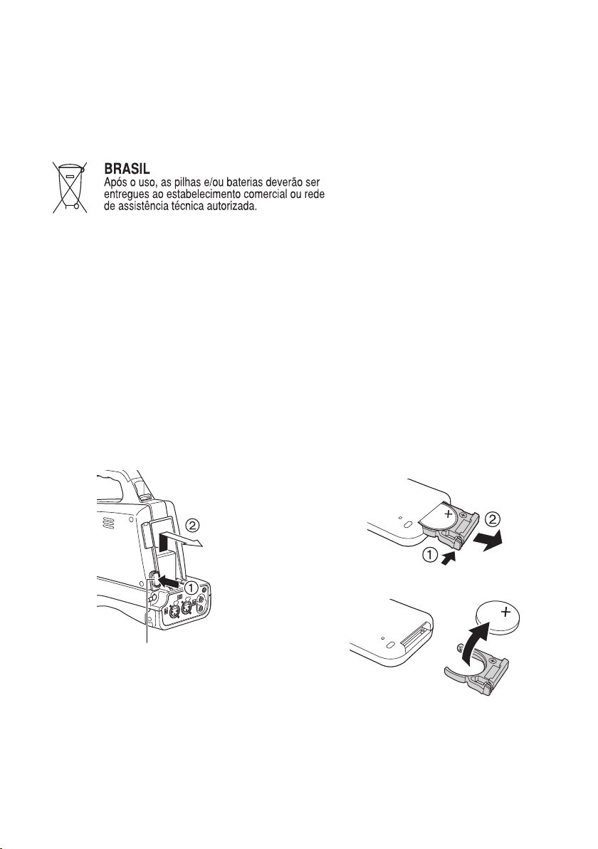
Para remover a bateria
212°F). O gás liberado pela bateria pode irritar a garganta,
Bateria Principal de Energia
Pressione o botão para liberar a bateria.
Botão de liberação da bateria
Bateria do Controle Remoto
1) Empurre a trava na direção exibida pela seta
A para remover o suporte.
2) Remova a bateria tipo botão do suporte da
bateria.
5
Page 6

*1: Please note that this extended warranty is not available in some countries/regions. *2: Not all models eligible for extended warranty coverage.
*3: The basic warranty period may vary depending on the country/region. *4: Not all repair work is covered by this extended warranty.
Purchase
AVCCAM product
Register online
within 1 month
“Registration Notice”
e-mail sent
Details about user registration and the extended warranty: http://panasonic.biz/sav/pass_e
Free 3 years of Warranty Repairs
Customers who register as users on the website will receive an extended warranty repair valid for up to
three years.
AVCCAM 3 Year Warranty Repair Program*
1
Thank you for purcha sing this Pan asonic AVCCAM device.
Register as a user f or this devic e to receive a special service warrant y up to three years of free warranty repairs.
Make sure to save the “Registration Notice” e-mail
during the warranty period.
1st year 2nd year 3rd year
AVCCAM device
*
2
Basic warranty
*
3
Extended warranty repair
*
4
●
SDHC Logo is a trademark of SD-3C, LLC.
●
“AVCHD” and the “AVCHD” logo are trademarks of Panasonic Corporation and Sony Corporation.
●
This product has been manufactured under license from Dolby Laboratories.
Dolby and the double-D symbol are trademarks of Dolby Laboratories.
●
HDMI, the HDMI logo, and High-Definition Multimedia Interface are trademarks or registered trademarks
of HDMI Licensing LLC in the United States and or other countries.
●
Microsoft
United States and/or other countries.
●
Screenshots are used in accordance with Microsoft Corporation guidelines.
●
Apple
States and/or other countries.
●
Other model names, company names, and product names listed in these operating instructions are
trademarks or registered trademarks of their respective companies.
●
This product is licensed under the AVC Patent Portfolio License for the personal and non-commercial
use of a consumer, and no license is granted or shall be implied for any use other than the personal
uses detailed below.
– To encode video in compliance with the AVC standard (“AVC Video”)
– To decode AVC Video that was encoded by a consumer engaged in a personal and non-commercial activity
– To decode AVC Video that was obtained from a video provider licensed to provide AVC Video
– Separate license contracts must be obtained from MPEG LA where SD Memory Cards containing information
Note concerning illustrations in these instructions
•
Illustrations (camera-recorder, menu screens, etc.) in these operating instructions differ slightly from the
actual camera-recorder.
®
and Windows® are trademarks or registered trademarks of Microsoft Corporation in the
®
, Macintosh®, and Mac OS® are trademarks or registered trademarks of Apple Inc. in the United
• Additional information may be obtained from MPEG LA, LLC (http://www
.mpegla.com).
recorded with this product are to be distributed to end users for commercial purposes. “End user” refers to
persons or organizations handling such contents for personal use.
References
•
References are shown as (Page 00).
Terminology
•
Both SD Memory Cards and SDHC Memory Cards as referred to as “SD Memory Cards” in these
operating instructions.
Video that is created during a single recording operation is referred to as a “clip” in these operating
•
instructions.
6
Page 7

Contents
Volume 1 (This Book)
Read this first! ..............................................2
IMPORTANT SAFETY INSTRUCTIONS .......4
Operating precautions .................................8
Precaution for use ......................................10
SD Memory Cards compatible with
this product ............................................... 12
(SD speed class 6)..................... 14
SDHC Memory Cards ................................... 14
Compatibility of recorded video .................... 15
About AVCHD ............................................... 15
About DV ...................................................... 15
Outline .................................... 16
Using this Camera ........................................ 16
Shooting and playing back with
this camera ............................................... 16
Editing and saving with external devices ...... 17
Accessories ................................................18
Optional accessories .................................19
Using tele conversion lenses,
wide conversion lenses ............................ 19
Description of parts ....................................20
Front side and rear side ............................... 20
Right Side ..................................................... 21
Left side ........................................................ 22
Remote control ............................................. 23
Preparation............................. 24
Recharging the battery ..............................24
Recharging ................................................... 24
Power sources ............................................26
Using the battery .......................................... 26
Using the AC adaptor ................................... 26
Adjusting the grip belt ...............................27
Attaching the shoulder strap .....................27
Detaching and attaching the lens hood ...28
Fitting the eye cup ......................................28
The remote control .....................................29
Insert the battery .......................................... 29
Remote control usable range ....................... 29
Basic Operations ................... 30
Turn on/off the camera ...............................30
Tally lamp ....................................................30
Using the cursor button .............................31
Basic operations ........................................... 31
Menu screen operations ............................... 31
Playback mode (PB mode only) .................. 31
Using the viewfinder ..................................32
Using the viewfinder ..................................... 32
Using as a LCD monitor ............................... 33
Emphasizing outlines ................................... 33
Adjusting the screen display ......................... 34
Setting the calendar ...................................35
Setting the time zone .................................... 35
Setting the clock ........................................... 35
Basic shooting operations ........................36
Preparing for recording ................................. 36
SD Memory Card ACCESS lamp ................. 36
Shooting in auto mode ................................. 37
Checking photos taken (REC CHECK) ........ 38
Using the zoom function ............................39
Digital zoom function .................................... 39
Using the setup menus ..............................40
Using the menus .......................................... 40
Using the Function Menu ............................. 41
Initializing the menu settings ........................ 41
Setup menu structure ................................42
CAMERA mode menu .................................. 42
PHOTO mode menu ..................................... 43
DV IN mode menu ........................................ 43
PB mode menu ............................................. 44
Thumbnail menu (DV mode only) ................. 44
Specifications ........................ 45
Index ....................................... 48
Volume 2 (CD)
Chapter 1: Operations in AVCHD mode
Chapter 2: Operations in DV mode
Chapter 3: Screen displays and setting
menus
Chapter 4: Reference
Before calling for service/Updating the firmware/
Cleaning/Cleaning the eye piece/Storage
Precautions/Software information/Recording
format/How to handle data recorded on SD
Memory Card
7
Page 8

Operating precautions
Do not allow any water to get into the camerarecorder when using it in the rain or snow or at
the beach.
Failure to heed this caution will cause the
•
camera-recorder or a card to malfunction (and
may result in irreparable damage).
Keep the camera-recorder away from
equipment (such as TV sets and video game
machines) that generate electromagnetic fields.
Using the camera-recorder on top of or near a
•
TV set may cause distortion in the images and/or
sound due to the electromagnetic waves that the
set emits.
The powerful magnetic fields generated by
•
speakers or large motors may damage your
recordings or distort the images.
The electromagnetic waves emitted from a
•
microcomputer will adversely affect the camerarecorder, causing the images and/or sound to be
distorted.
If the camera-recorder is so adversely affected by
•
products that generate magnetic fields that it no
longer operates properly, turn it off and remove
the battery or unplug the AC adaptor from the
power outlet. Then install the battery again or
reconnect the AC adaptor. After this, turn the
camera-recorder back on.
Do not use the camera-recorder near radio
transmitters or high-voltage equipment.
Using the camera-recorder near a radio
•
transmitter or high-voltage equipment may
adversely affect the recorded images and/or
sound.
Do not allow any sand or dust to get into the
camera-recorder when using it at the beach
and other similar places.
Sand and dust can damage the camera-recorder
•
or a card. (Be especially careful when inserting or
removing a card.)
AC adaptor and battery
If the CHARGE lamp continues to blink even
•
when the battery temperature is normal, there
may be something wrong with the battery or AC
adaptor. Contact your dealer.
The battery takes longer to charge when it is
•
warm.
The AC adaptor can interfere with radio reception
•
so keep radios at least 1 meter away from it.
The AC adaptor may make some noise when you
•
are using it, but this is normal.
Take precautions not to drop the camera when
moving it.
Strong impacts may damage the camera and
•
cause it to stop working.
Handle the camera with care, using the hand
•
strap or shoulder strap to carry it.
Do not spray the camera with insect sprays or
other volatile substances.
These can warp the camera or cause the finish
•
to come off.
Do not leave the camera-recorder in contact with
•
rubber or PVC products for extended periods of
time.
After use, remove the battery and disconnect
the AC power supply cable.
Battery characteristics
This camera-recorder uses a rechargeable lithiumion battery that uses its internal chemical reaction
to generate electrical energy. This reaction is
easily influenced by the ambient temperature and
humidity, and the battery’s effective operating time
is reduced as the temperature rises or falls. In
very low temperatures, the battery may last only 5
minutes.
Protective circuitry functions if you use the battery
where it is very hot and you will have to wait before
you can use it again.
Remove the battery after use.
Completely remove the battery. (The battery
continues to be used even if you have turned
the camera off.) The battery can over discharge
if you leave it in the camera and it may become
impossible to recharge it.
Disposing of spent batteries
The battery will become unchargeable. Rather than
throwing the battery into the garbage, take it to a
store that can assist in recycling it.
8
Page 9

What to remember when throwing memory
cards away or transferring them to others
Formatting memory cards or deleting data using
the functions of the unit or a computer will merely
change the file management information: it will
not completely erase the data on the cards. When
throwing these cards away or transferring them
to others, either physically destroy them or use a
data deletion program for computers (commercially
available) to completely erase the data. Users are
responsible for managing the data on their memory
cards.
Liquid crystal displays
Images or letters can get burned onto the
•
viewfinder’s LCD monitor if they are displayed
for a long time, but you can fix this by leaving the
camera off for several hours.
The pixels of the LCD monitor are controlled to
•
obtain high precision with 99.99 % of the effective
pixels. This leaves less than 0.01 % of pixels
that may not light or may remain on all the time.
These phenomena are normal and will have no
effect on the images you shoot.
Condensation may form if you use the camera
•
where temperatures fluctuate. Wipe dry with a
soft, dry cloth.
The viewfinder’s LCD monitor may appear dim
•
after immediately turning on a cold camera, but
will brighten as the camera warms up.
Do not point the lens or viewfinder at the sun.
Doing so may damage the parts inside.
Protective caps for the connectors
Keep the protective caps fitted over any
connectors that are not being used.
9
Page 10
Precaution for use
Always take some trial shots before actual shooting.
When shooting important events (such as weddings), always take some trial shots and check that the
•
sound and images have been recorded properly before actual shooting.
Be sure to check and set the calendar and time zone.
These settings affect the control of the recorded contents. Before making a recording, set and check the
•
calendar and time zone. (Page 35)
Panasonic makes no guarantees for your recordings.
Please understand that Panasonic makes no guarantees for your recordings in cases where images and/
•
or sound were not recorded as you intended due to problems with the camera-recorder or SD/SDHC
Memory Cards.
Respect copyrights
Copyright laws forbid the use of video and audio material you have recorded for any purpose other than
•
your own personal enjoyment. Remember that restrictions apply to the shooting of certain material even
if it is intended for private use.
Media that can be used in this unit
SD/SDHC Memory Cards can be used in this unit. For details, refer to page 12.
•
SDXC Memory Cards cannot be used with this product.
•
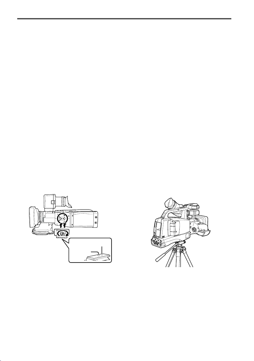
Tripod receptacle
The tripod receptacle is a hole used to mount a tripod for the unit. (For details on mounting the tripod, refer
to the operating instructions for the tripod.)
Compatible with the ISO1222 (1/4) standard.
•
The tripod mounting hole is 5.5 mm deep. Do not force the tripod screw beyond this depth.
•
You can damage the camera-recorder if you use any screw other than 1/4-20UNC.
10
Camera
Camera
base
base
Screw for
Screw for
mounting
mounting
the unit
the unit
Tripod pin
Tripod pin
When using the tripod, operations can be
•
performed more easily using a remote control
connected to the CAM REMOTE jack.
Page 11
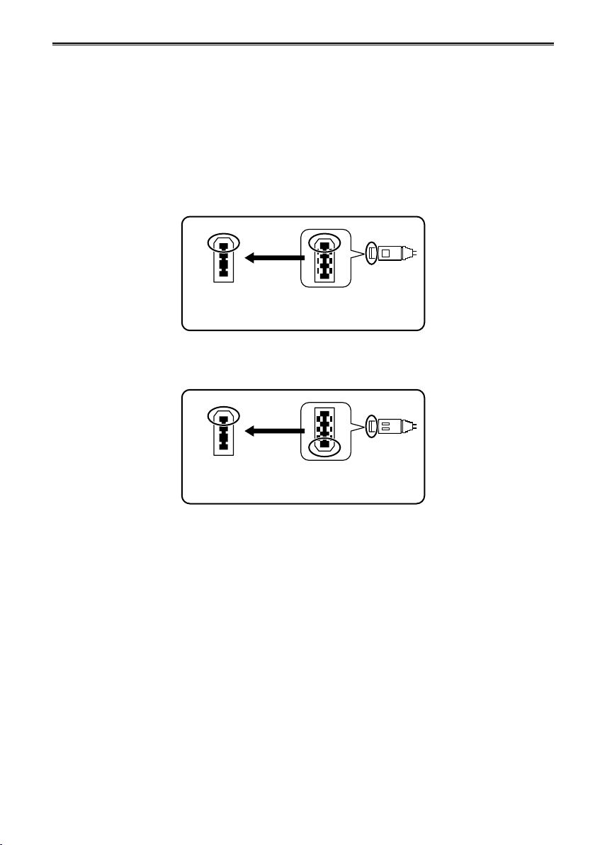
Connecting the IEEE1394 cable
Always heed the following instructions when connecting the IEEE1394 cable (not included.) (If it is
connected incorrectly, this may lead to the failure of this camera or external devices.).
Connect or disconnect the IEEE1394 cable after switching off the power of all connected devices.
•
Devices with an earth terminal should be earthed (or connected to a shared GND) when using them.
When connecting this camera to devices with a 4-pin terminal, connect this camera’s terminal (6-pin) in
•
advance.
The terminal of the IEEE1394 cable has an orientation.
•
When connecting the cable to an external device with a 6-pin IEEE1394 terminal, connect it as per with
•
the following configuration.
(Correct)
IEEE1394
terminal
× (Incorrect)
IEEE1394
terminal
For other usage notes, see page 8.
End of the IEEE1394
cable
End of the IEEE1394
cable
11
Page 12

Precaution for use (continued)
SD Memory Cards compatible with this product
AVCHD mode
It is recommended that you use SD Memory Cards or SDHC Memory Cards* of SD speed class 2 or
above, or the following Panasonic SD Memory Cards (correct as of August 2010).
Speed class 4 or above is required for recording in PH mode or HA mode. SDXC Memory Cards cannot
*
be used with this product.
Card type Recording capacity Recording/playback
8 MB
16 MB
32 MB
64 MB
128 MB
SD Memory
Card
SDHC Memory
Card
Please see our support page at the following website for the latest information not included in these
•
256 MB
512 MB RP-SDV512
1 GB
2 GB
4 GB
6 GB RP-SDM06G
8 GB
12 GB
16 GB
32 GB
Cannot be used.
Successful operation cannot be
guaranteed. Recording may be
suddenly terminated with certain
SD Memory Cards.
RP-SDV01G
RP-SDM01G
RP-SDV02G
RP-SDM02G
RP-SDP02G
RP-SDV04G
RP-SDM04G
RP-SDW04G
RP-SDP04G
RP-SDV08G
RP-SDM08G
RP-SDW08G
RP-SDP08G
RP-SDM12G
RP-SDP12G
RP-SDV16G
RP-SDM16G
RP-SDW16G
RP-SDP16G
RP-SDV32G
RP-SDW32G
RP-SDP32G
operating instructions.
http://pro-av.panasonic.net/
This product is compatible with SD Memory Cards formatted under the SD-standard FAT12 and FAT16
•
formats, and with SDHC Memory Cards formatted under the FAT32 format.
Only SDHC Memory Cards may be used for capacities of 4 GB or greater.
•
4 GB (or greater) memory cards without the SDHC logo are not based on the SD standard.
•
Use this product to format the SD Memory Cards to be used. Formatting memory cards on computers
•
or other devices may cause recording to take longer than normal, or may cause cards to become
incompatible with this product. (Page 28 of Vol.2) (Use this product to reformat any cards that have
already been formatted on computers, etc.)
Always install the relevant special adapter when using microSD/microSDHC cards with this product. (The
•
product will not operate correctly if only the adapter is inserted – always insert a memory card into the
adapter first.)
MultiMediaCards cannot be used with this product.
•
Photo shooting
Loading metadata
Can be used.
12
Page 13

DV mode
When shooting in DV mode, it is necessary to use SD Memory Cards or SDHC Memory Cards* of speed
class 6 or above.
It is recommended that you use the following Panasonic SD Memory Cards (as of August 2010).
SDXC Memory Cards cannot be used with this product.
*
Card type Recording capacity Recording/playback
8 MB
16 MB
32 MB
SD Memory
Card
SDHC Memory
Card
Please see our support page at the following website for the latest information not included in these
•
64 MB
128 MB
256 MB
512 MB RP-SDV512
1 GB RP-SDV01G
2 GB RP-SDV02G
4 GB
8 GB
16 GB
32 GB
operating instructions.
http://pro-av.panasonic.net/
This product is compatible with SD Memory Cards formatted under the SD-standard FAT12 and FAT16
•
formats, and with SDHC Memory Cards formatted under the FAT32 format.
Only SDHC Memory Cards may be used for capacities of 4 GB or greater.
•
4 GB (or greater) memory cards without the SDHC logo are not based on the SD standard.
•
Use this product to format the SD Memory Cards to be used. Formatting memory cards on computers
•
or other devices may cause recording to take longer than normal, or may cause cards to become
incompatible with this product. (Page 76 of Vol.2) (Use this product to reformat any cards that have
already been formatted on computers, etc.)
Always install the relevant special adapter when using microSD/microSDHC Memory cards with this
•
product. (The product will not operate correctly if only the adapter is inserted – always insert a memory
card into the adapter first.)
MultiMediaCards cannot be used with this product.
•
Cannot be used.
Cannot be used.
RP-SDV04G
RP-SDW04G
RP-SDV08G
RP-SDW08G
RP-SDV16G
RP-SDW16G
RP-SDV32G
RP-SDW32G
13
Page 14
Precaution for use (continued)
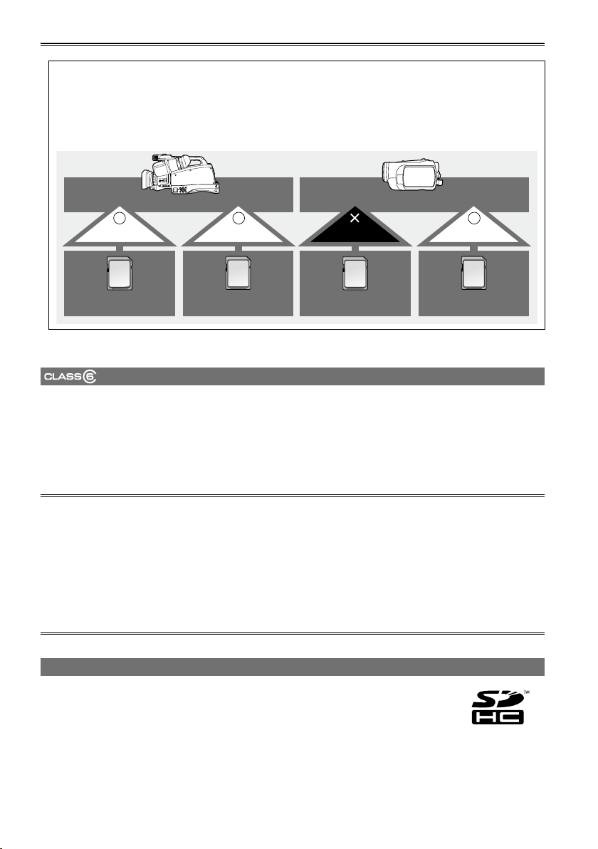
This product (SDHC-compatible device) is compatible both with SD Memory Cards and with
SDHC Memory Cards. SDHC Memory Cards may be used with SDHC Memory Card-compatible
devices, but cannot be used with devices that are only compatible with SD Memory Cards.
(Always check the relevant product’s operating instructions when using SDHC Memory Cards
with other devices.)
SDHC-compatible device
Can be used Can be used Cannot be used Can be used
SDHC Memory Card SD Memory Card SDHC Memory Card SD Memory Card
SD-compatible device
(SD speed class 6)
This refers to a class 6 speed standard (SD speed class) for the continuous writing of data between SDcompatible devices and SD Memory Cards, as designated by the SD standards.
When the use of an SD speed class 6 card is recommended for SD-compatible products, this indicates
that stable recording operation can be achieved when using SD Memory Cards of class 6 and above.
Speed class 4 or above is required for recording in AVCHD mode, or 6 or above for DV mode when
•
shooting with this camera.
Cautions for usage
Do not allow dirt, water, or other substances to come into contact with the connector part on the
•
reverse of the card.
Do not leave the card in the following places:
•
– In direct sunlight or in places of high humidity, e.g. close to heating equipment
– In highly humid or dusty locations
– In locations with high variations in temperature (condensation may appear on card)
– In places subject to static electricity or electromagnetic waves
Store cards in bags or cases after use.
•
SDHC Memory Cards
SDHC Memory Cards cannot be used with non-SDHC-compatible equipment.
●
Ensure that all equipment is SDHC-compatible when using card with other devices.
●
14
Page 15

Compatibility of recorded video
Shooting video in AVCHD mode
Recorded video cannot be used with non-AVCHD-compatible equipment. For details, please see your
●
product’s operating instructions.
Recorded video cannot be played back on non-compatible (non-AVCHD-compatible) equipment.
●
Playback may not always be possible on all AVCHD-compatible equipment. Please use this product for
●
playback in such instances.
Shooting video in DV mode
It is not compatible with AV devices fitted with a Panasonic SD Memory Card slot (DIGA, VERA, TV,
●
digital video camera).
Video is recorded in AVI Type 2 file format and can be played back on computers using AVI Type2-
●
compatible media players.
About AVCHD
AVCHD is a standard for the recording and playback of highly detailed, high-definition video.
●
Video is compressed in the MPEG-4 AVC/H.264 formats, and audio is recorded in Dolby Digital.
●
About DV
It uses the AVI Type 2 file format and can play back with the DV compatible mode.
●
Sound is recorded using the 2 ch uncompressed linear PCM system.
●
15
Page 16

Outline
MODE
CAMERA
PHOTO IN
DVAVCHD
PB
MODE
CAMERA
PHOTO IN
DVAVCHD
PB
Using this Camera
Outline
This camera is mounted with a 1/4.1-type MOS sensor x 12, and is a shoulder type camera recorder that
uses SD/SDHC memory cards for recording media.
It can record and play back SD images (DV mode) in addition to recording and playing back HD images
(AVCHD mode) with 1080 and 720 scan lines.
Shooting and playing back with this camera
AVCHD mode
• HD (hi-vision) shooting
• Shoots photos
• Connects to PCs (USB mode)
• Prints photos with a printer (PictBridge)
DV mode
• SD shooting
• DV (IEEE1394) input/output
AVCHD mode
■
Video shooting (CAMERA mode)
•
Shooting in auto mode (Page 37)
Shooting in manual mode (Page 5 of Vol.2)
Photo shooting (PHOTO mode)
•
Shooting photos (Page 31 of Vol.2)
Playback (PB mode)
•
Playing back clips (Page 40 of Vol.2)
Playing back photos (Page 42 of Vol.2)
Other functions
•
Connecting to a computer (USB mode)
(Page 53 of Vol.2)
Printing photos on a printer (PictBridge)
(Page 47 of Vol. 2)
DV mode
■
Video shooting (CAMERA mode)
•
Shooting in auto mode (Page 37)
Shooting in manual mode (Page 54 of Vol.2)
Playback (PB mode)
•
Playing back clips (Page of 84 Vol.2)
Other functions (DV IN mode)
•
DV (IEEE1394) output and input (Pages 73,
90 of Vol.2)
16
Page 17

MODE
CAMERA
PHOTO IN
DVAVCHD
PB
B
A
R
S
C
O
U
N
T
E
R
R
E
S
E
T
Z
E
B
R
A
MODE
CAMERA
PHOTO IN
DVAVCHD
PB
Editing and saving with external devices
SD/SDHC Memory Card (class 4
or above for PH and HA modes)
AVCHD mode
HDMI cable (optional)
Video cable (BNC) (optional)
• Select AVCHD with the
MODE switch, and then turn
on the camera.
There is no DV (1394) input/output function.
*
DV mode
Audio cable (RCA) (optional)
Component cable (BNC) (optional)
SD/SDHC Memory Card
(class 6 or above)
Outline
PC (Pages 51, 122 of Vol.2)
USB 2.0
Printer (Page 47 of Vol.2)
USB 2.0
Video device / TV / monitor
(Pages 51, 52 of Vol.2)
PC (Page 122 of Vol.2)
IEEE1394 (DV) cable (optional)
• Select DV with the MODE
switch, and then turn on
the camera.
There are no USB connection and HDMI output functions.
*
Video cable (BNC) (optional)
Audio cable (RCA) (optional)
Component cable (BNC) (optional)
DV tape device / memory card
recorder (backup, dubbing,
editing) (Pages 88, 90 of Vol.2)
Video device / TV / monitor
(Pages 87, 89 of Vol.2)
17
Page 18

Accessories
1
Battery
Outline
*
Eye cup
→ See “Fitting the eye
cup”. (Page 28)
The following accessories are attached to the unit.
Lens hood cap Lens hood Lens hood (inner) Grip belt
XLR audio adaptor
cap
AC Adaptor
Shoulder strap
→ See “Attaching the
shoulder strap”.
(Page 27)
AC power supply cable/
DC cable
CD-ROM
Wireless remote
control and battery
(CR2025)
For part numbers for the battery, see “Optional accessories”. (Page 19)
*1
Please consult a retailer when purchasing additional accessories.
•
After removing the package contents, discard the packaging materials appropriately.
•
Some of the supplied accessories may not be manufactured in Japan.
•
18
Page 19

Optional accessories
Battery
•
VW-VBG260 (7.2 V, 2640/2500 (typ./min.) mAh: equivalent to accessory battery)
VW-VBG6 (7.2 V, 5800/5400 (typ./min.) mAh: compatible with supplied battery charger)
Tele conversion lens
•
VW-T4314H (See below for attachment instructions.)
Wide conversion lens
•
VW-W4307H (See below for attachment instructions.)
Using tele conversion lenses, wide conversion lenses
Remove both the lens hood and lens hood (inner) before attaching an optional VW-T4314H tele
conversion lens or VW-W4307H wide conversion lens. For details on removing the lens hood, see page
28.
Removing and attaching the lens hood (inner)
Outline
Remove Attach Align the grooves.
Attach the ND filter and MC protector to the front of the lens hood (inner).
•
Although you can attach both a filter and a conversion lens at the same time (such as attaching both
•
an ND filter and a tele conversion lens), we do not recommend it, as the corners of images may
appear darker (vignetting) during wide-angle zoom. (If you do attach both at the same time, remove
the lens hood (inner) first.)
19
Page 20

Description of parts
VIDEO
COMPONENT
ON
LINE MIC LINE MIC
OFF OFF
AUDIO
IN
AUDIO
OUT
MIC+48V
ON
MIC+48V
CH 1 CH 2 CH 2
CH 1
OFF
ON
POWER
6 7
14 1513 16
5 8
41 10 11 124 92 3
Front side and rear side
Outline
1 Handle zoom switch (Page 39)
2 Handle zoom lever (Page 39)
3 Handle START/STOP button
(Pages 10, 59 of Vol.2)
4 Shoulder belt installation hole (Page 27)
5 REC CHECK/PHOTO SHOT button
(Page 38, Page 31 of Vol.2)
6 Zoom lever (Page 39)
7 Remote control sensor (Page 29)
8 Tally lamp (FRONT) (Page 30)
9 Viewfinder (Page 32)
10 Accessory shoe
11 START/STOP button (Page 37)
12 POWER switch (Page 30)
13 Lock button (Page 33)
14 Battery release button (Page 26)
15 Battery compartment (Page 26)
16 Tally Lamp (REAR) (Page 30)
20
Page 21

MONITOR
DV
PHONE
AUDIO LEVEL
CH1 CH2
MODE
CAMERA
PHOTO IN
DVAVCHD
AUDIO SELECT
COUNTER RESET/ TC SET
AUDIO IN
CH1
AUTO
MAN
FRONT
REAR
CH2
REC
SPEED SEL
ZEBRABARS
DISP / MODE CHK
FOCUS ZOOM/
IRIS
WHITE
BAL
USER 1 USER 2 USER 3
AUTO/
MANUAL
SHUTTER
IRISFOCUSFOCUS ASSIST
PB
OIS
PAGE / ADV
FUNC / EXEC
MENU
ENTER
AUTO
MANUAL
PUSH
MONITOR
AUDIO LEVEL
CH1 CH2
MODE
CAMERA
PHOTO IN
DVAVCHD
AUDIO SELECT
COUNTER RESET/ TC SET
AUDIO IN
CH1
AUTO
MAN
FRONT
REAR
CH2
REC
SPEED SEL
ZEBRABARS
DISP / MODE CHK
SHUTTER
PB
OIS
AUTO
MANUAL
PAGE / ADV
FUNC / EXEC
MENU
ENTER
29 3130 32 33 34
35 36 37 39 4241 4338 40
24 2523 26 27 28
46 47 4948
17 2118 19 2220
44 45
Right Side
17 Built-in microphone
18 FOCUS ASSIST button (Pages 6, 55 of Vol.2)
19 FOCUS button (Pages 5, 54 of Vol.2)
20 IRIS dial (Pages 6, 55 of Vol.2)
21 Diopter adjustment lever (Page 32)
22 Speakers
23 FOCUS ring (Pages 5, 54 of Vol.2)
24 RING switch (Pages 5, 54 of Vol.2)
25 WHITE BAL button (Pages 7, 56 of Vol.2)
26 USER1 - 3 button (Pages 12, 61, 107 of Vol.2)
27 Memory Card cover (Page 36)
28 ACCESS lamp (Page 36)
29 SHUTTER button (Pages 15, 65 of Vol.2)
30 SPEED SEL -/+ button
(Pages 15, 65 of Vol.2)
31 OIS button (Pages 11, 60 of Vol.2)
32 MODE button
(Page 31, Pages 31, 40, 42, 90 of Vol.2)
33 MONITOR LEVEL knob (Page 42 of Vol.2)
34 AUDIO LEVEL knob (Pages 20, 70 of Vol.2)
35 DISP/MODE CHK button
(Pages 11, 60 of Vol.2)
36 BARS button (Pages 12, 61 of Vol.2)
37 ZEBRA button (Pages 10, 59 of Vol.2)
38 MODE switch (Page 37)
39 AUTO/MANUAL switch
(Page 37, Pages 5, 54 of Vol.2)
40 AUDIO SELECT switch
(Pages 20, 70 of Vol.2)
41 COUNTER button (Pages 25, 73 of Vol.2)
42 RESET/TC SET button
(Pages 25, 73 of Vol.2)
43 AUDIO IN CH1/CH2 switch
(Pages 18, 68 of Vol.2)
44 HDMI terminal (Page 52 of Vol.2)
45 USB2.0 terminal (Page 51 of Vol.2)
46 MENU button (Page 40)
47 PAGE/ADV -/+ button (Pages 35, 37 of Vol.2)
48 Cursor button (Page 31)
49 FUNC/EXEC button (Page 41)
Outline
21
Page 22

Description of parts (continued)
ON
LINE MIC LINE MIC
OFF OFF
AUDIO
IN
AUDIO
OUT
MIC+48V
ON
MIC+48V
CH 1 CH 2 CH 2
CH 1
VIDEO
COMPONENT
OUTPUT
CAMREMOTE
ZOOM
S/S
FOCUS
IRIS
Y/
VIDEO
P
B
P
R
58
54
5756 5655
60 61
50
53
51
52
59
Left side
Outline
50 OUTPUT switch (Pages 52, 89 of Vol.2)
51 VIDEO terminal (BNC)/ COMPONENT OUT
(Y/PB/PR) terminal (BNC)
(Pages 52, 89 of Vol.2)
52 CAM REMOTE jacks
*
FOCUS/IRIS (3.5 mini jack)
You can connect a remote control unit to control
the FOCUS and IRIS (aperture). IRIS (aperture)
control beyond OPEN is performed via gain
adjustment, and can be set up to the standard
gain setting.
ZOOM S/S (2.5 mm super mini jack)
You can connect a remote control unit to control
zoom and start/stop of recording.
53 DV terminal (Page 88 of Vol.2)
54 Input audio selection switch
(Pages 19, 69 of Vol.2)
55 PHONES (headphone) terminal
(Pages 50, 86 of Vol.2)
22
56 MIC + 48 V ON/OFF switch
(Pages 19, 69 of Vol.2)
57 XLR input (CH1/CH2) terminal
(Pages 19, 69 of Vol.2)
58 AUDIO OUT (CH1/CH2) terminal
(Pages 52, 87, 89 of Vol.2)
59 Left and right position lock ring (Page 32)
60 EXT MIC terminal (Pages 50, 86 of Vol.2)
61 Grip belt (Page 27)
Do not connect any equipment except the
*
remote controller to the remote control jack.
Connecting any equipment other than the
remote control may cause the image brightness
to change and/or the images to appear out of
focus.
Page 23

ZOOM
START/
STOP
PHOTO
SHOT
EXT
DISPLAY
DATE/
TIME
VOL
PLAY
STOPSKIP SKIP
MENU
ENTER
PAUSE
SEARCH
STILL ADV STILL ADV
SEARCH
4
5
7
9
1
2
6
8
9
10
11
13
3
7
12
11
14
15
Remote control
To use the remote control, set the IR REMOTE item on the OTHER FUNCTIONS menu to ON. The default
setting for this item is OFF. (Page 110 of Vol.2)
1 EXT. DISPLAY button (Pages 49, 85 of Vol.2)
2 DATE/TIME button (Pages 49, 85 of Vol.2)
3 PHOTO SHOT button (Page 31 of Vol.2)
Performs only the PHOTO SHOT function of
the REC CHECK/PHOTO SHOT button on the
camera.
4 START/STOP button (Page 37)
5 ZOOM/VOL buttons (Page 39)
The sound volume of the camera cannot be
adjusted using the remote control.
6 PLAY button (Pages 41, 84 of Vol.2)
7 SEARCH buttons (Pages 40, 41, 84 of Vol.2)
Remote control usable range (Page 29)
8 PAUSE button (Pages 40, 41, 84 of Vol.2)
9 STILL ADV buttons (Pages 41, 84 of Vol.2)
10 STOP button (Pages 40, 84 of Vol.2)
11 SKIP buttons (Pages 40, 84 of Vol.2)
button
12
Does not function with this camera.
13 OPERATION buttons
Same function as the cursor button (menu
operation) on the camera.
14 MENU button
Same function as the MENU button on the
camera.
15 ENTER button
Confirms menu and item selections.
Outline
23
Page 24

Preparation
Recharging the battery
Recharging
Preparation
The battery does not come ready charged when
the camera is purchased. Charge the battery
before use.
It is recommended that you keep one extra battery
as a spare.
Connect the power cable to the AC adaptor.
1
Disconnect the DC cable.
(Battery cannot be charged if DC cable is
connected.)
Insert until fully in place.
Insert the battery.
2
Charging lamp [CHARGE]
Align the battery with the
Charging lamp
■
On: Charging in progress
Off: Charging complete
Flashing: See below
mark and insert fully.
Charging time and available recording time
■
(Approx.)
Battery
model
VW-VBG260
(included)
VW-VBG6
(optional)
The figures in the table above are guidelines
•
for use in normal temperature conditions
(temperature 25 °C (77 °F), humidity 60 %).
Charging may take longer in higher or lower
temperatures.
Charging may take longer if the battery has not
•
been in use for a long period of time.
The maximum continuous recording times given
•
here assume that the camera is recording in DV
mode with no external devices connected.
Available recording time may vary according to
•
usage conditions.
Charging times are based on charging batteries
•
from an empty state.
Voltage/
capacity
7.2 V/
2640/2500
(typ./min.)
mAh
7.2 V/
5800/5400
(typ./min.)
mAh
Charging
time
Approx.
170 min.
Approx.
350 min.
Maximum
continuous
recording time
Approx.
85 min.
Approx.
170 min.
If charging lamp is flashing
■
Check that there is no dirt, dust, or other
substances attached to the connectors on the
battery or AC adaptor, and ensure that the adapter
has been connected correctly.
If there is dirt or dust on the connectors,
•
disconnect the power plug from the socket before
cleaning.
If the charging lamp continues to flash, there
•
may be a fault with the battery or the AC adaptor.
Please consult with the place of purchase.
24
Page 25

Remaining battery capacity displays
■
When using Panasonic-manufactured batteries
compatible with this product, the remaining battery
capacity is displayed in minutes.
90min.
Time remaining will be displayed after a brief
pause.
The battery display will change
•
→ → → →
as battery capacity decreases. will be
displayed in red when less than 3 minutes are
remaining, and will flash when the battery
is empty.
Remaining battery capacity may not be displayed
•
correctly when using in high or low temperatures,
or when the battery has not been used for a
long period of time. To ensure that remaining
battery capacity is displayed correctly, use the
battery completely from a fully-charged state,
and charge the battery again. (Remaining battery
capacity may still not be displayed correctly if the
battery has been used for long periods in high
or low temperatures, or if the battery has been
recharged a large number of times.)
The remaining battery capacity display is a
•
guideline and may change according to usage
conditions.
The remaining battery capacity display will
•
momentarily disappear when switching between
modes, when conducting REC CHECK
operations or when changing the LCD brightness
since the capacity is recalculated at these times.
Not displayed when using AC adaptor.
•
The maximum time display for the remaining
•
battery capacity is 999 minutes.
If the remaining battery capacity exceeds 999
•
minutes, the remaining time is displayed in green.
This display does not change until the remaining
time reaches 999 minutes or below.
Keep metal objects (such as necklaces and
•
hairpins) away from the battery.
Short-circuiting may occur across the
terminals, causing the battery to heat up,
and you may seriously burn yourself if you
touch the battery in this state.
The battery becomes hot while it is being used
•
or charged. The camera-recorder itself also
becomes hot during use.
The recordable time reduces if you repeatedly
•
start and stop recording.
The battery takes longer to charge when it is
•
warm.
The AC adaptor can interfere with radio
•
reception so keep radios at least 1 meter away
from it.
The AC adaptor may make some noise when
•
you are using it, but this is normal.
Battery cannot be recharged when the DC
•
cable is connected to the AC adaptor.
Preparation
25
Page 26

Power sources
%1/210'06
Using the battery
Installation
Insert the battery until it clicks into place.
Preparation
Using the AC adaptor
Installation
Connect the DC cable to the AC adaptor.
1
Plug the AC power supply cable into the
2
power outlet.
Insert the DC cable’s battery connector until
3
it clicks into place.
Removal
Set the POWER switch to OFF, and check
1
that the mode lamp is off.
Remove the battery while pressing the
2
battery release button.
The lock can be released and the battery
•
removed.
Removal
Set the POWER switch to OFF, and check
1
that the mode lamp is off.
Remove the DC cable’s battery connector
2
while pressing the battery release button.
Disconnect the AC power supply cable from
3
the power outlet.
26
Battery cannot be recharged when the DC
•
cable is connected to the AC adaptor.
Disconnect the AC power supply cable from the
•
power outlet when the unit is not going to be used.
DC cable’s battery
connector
CAUTION:
This apparatus can be operated at a voltage in
•
the range of 110 – 240 V AC.
Voltages other than 120 V are not intended for
U.S.A. and Canada.
Operation at a voltage other than 120 V AC may
require the use of a different AC plug.
Please contact either a local or foreign
Panasonic authorized service center for
assistance in selecting an alternate AC plug.
Page 27

Adjusting the grip belt
Adjust the grip belt to suit your hand, and hold it
correctly.
Open the belt cover and loosen the belt.
1
Work your hand through the grip belt and
2
fasten the belt.
Slip your hand through the belt as far as
•
it goes.
Tighten up the belt so that your hand
•
remains firmly in place.
When loosening the belt, please take care so
•
that the belt does not come away from the grip
belt stopper.
Grip belt stopper
Preparation
Attaching the shoulder strap
Attach the shoulder strap and use it as a precaution against dropping the camera.
Thread the belt through the shoulder belt
1
installation hole.
Thread the belt through the fastener
•
after threading through the shoulder belt
installation hole. At least 2 cm of the belt
must extend from the fastener.
Shoulder belt
installation hole.
Install the belt on the other shoulder belt
2
installation hole.
27
Page 28

Detaching and attaching the lens hood
Detaching the lens hood
Turn the lens hood counterclockwise to detach it.•
Preparation
Attaching the lens hood
Orient the lens hood with the arrow mark on top,
•
rotate the hood counterclockwise (approx. 14˚) to
align the arrow with the one on the camera, and
then slide the hood onto the camera.
Rotate the lens hood clockwise to attach it.
•
Be sure to attach the lens hood cap to protect the
•
lens when not in use.
Lens hood
Attaching the lens hood cap
The lens can be covered by attaching the lens
hood cap provided to the lens hood.
Lens hood cap
Fitting the eye cup
To attach the eye cup, align the projections on the
eye cup holder and eye cup, and fit the holder and
eye cup together.
Eye cup
Projection
Eye cup holder
Turning the eye cup after attaching it to its holder
•
may cause the holder to become disengaged.
28
Page 29

The remote control
Insert the battery
Push the catch in the direction shown by
1
arrow ① to remove the holder.
Insert the battery with the “+” marked side
2
facing up.
Return the holder to its original position.
3
•
When the battery (CR2025) has run out, replace
it with a new one. (The battery lasts about one
year, depending on the frequency of use.)
If the remote control unit fails to work even when
it is operated near the camera-recorder’s remote
control sensor, the battery has run out.
Keep the battery out of the reach of children.
•
Remote control usable range
The distance between the remote control and the
unit’s remote control sensor: Within approx. 5 m
Angle: Approximately 15° upward,
approximately 10° downward,
approximately 15° leftward, or
approximately 15° rightward
(Except when optional accessories are
attached)
Remote control
sensor
The remote control is intended for indoor
•
operation. Outdoors or under strong light, the unit
may not operate properly even within the usable
ranges.
The default setting for this item is OFF. To use
•
the remote control, set the IR REMOTE item
on the OTHER FUNCTIONS menu to ON.
(Page 110 of Vol.2)
Preparation
29
Page 30

OFF
ON
POWER
CAMERA
PHOTO IN
DVAVCHD
PB
ON
LINE MIC LINE MIC
OFF OFF
AUDIO
IN
AUDIO
OUT
MIC+48V
ON
MIC+48V
CH 1 CH 2 CH 2
CH 1
Basic Operations
Turn on/off the camera
While pressing the lock release button, move the
POWER switch to ON or OFF.
Turn on the camera:
The mode lamp (CAMERA) lights red (camera
Basic Operations
mode), and the camera enters recording standby
mode.
Turn off the camera:
The mode lamp (CAMERA) goes out.
Energy-saving mode
•
Depending on the setting made for the POWER
SAVE item of the OTHER FUNCTIONS screen
in the settings menu, the following will apply if
no designated operations* are performed for
approximately five minutes in the recording standby
modes of CAMERA mode and PHOTO mode (when
an SD Memory Card has been inserted while using
the battery).
ON:
The camera recorder turns off automatically.
OFF: Does not switch OFF the camera.
See the setup menus, POWER SAVE
*
(Page 111 of Vol.2) for details.
Tally lamp
You can set the tally lamp to light in the following
situations by setting the REC LAMP item
(Page 110 of Vol.2) in the OTHER FUNCTIONS
screen to OFF.
The tally lamp light can be switched to FRONT,
REAR or BOTH with the setting menu. For more
details, refer to the setting menu REC LAMP item
(Page 110 of Vol.2).
Battery is low (flashes 4 times per second)
•
Available SD Memory Card capacity is low
•
(flashes 4 times per second)
Remaining battery capacity is low
•
(flashes once per second)
Remaining memory of the SD Memory Card is
•
low (flashes once per second)
In addition, the location set for the REC LAMP
item will flash when receiving commands from the
remote control.
Mode lamp
POWER switch
Set the POWER switch to the
ON position while pressing the
lock release button.
The CAMERA lamp lights
(red), and the camera enters
recording standby mode.
Lock release button
Tally lamp (REAR)
Tally lamp (FRONT)
30
Page 31

ENTER
ENTER ENTER
Using the cursor button
This unit has a cursor button for selecting menu items and performing play back operations.
Basic operations
The following describes operations on the menu screen and selection of files on the thumbnail view screen
etc.
cursor button
Select an item by pressing the up, down, right,
or left button of the cursor button and enter
the selection by pressing the ENTER button.
Press the up, down, right, or left button of the
cursor button to select an item or a scene, and
press the ENTER button to enter it.
Basic Operations
Menu screen operations
Press the MENU button to display the menu.
1
The thumbnail menu is displayed when in
•
DV or PB mode. Press and hold the MENU
button to display the normal menu.
Select an item by pressing the ENTER
2
button.
Perform the same operation to select
•
additional items or to set numerical values.
Press the MENU button to exit the menu
3
screen.
Playback mode (PB mode only)
Press the MODE button and switch to PB
1
mode.
Select a clip or photo to play back with the
2
cursor button, and press the ENTER button.
Operate by pressing the up, down, right, or
3
left button of the cursor button.
31
Page 32

ヰョョ
ヰワ
ヱヰヸユン
Using the viewfinder
This camera has a viewfinder which uses a
retractable 69 mm (2.7 inch) LCD.
The brightness and hue may differ between
•
the images appearing on the viewfinder (LCD
monitor) and those displayed on a TV monitor.
To see how the final images will appear, check
them on a TV monitor.
Basic Operations
Using the viewfinder
Set the POWER switch to ON, and check
1
that images appear in the viewfinder.
Adjust the angle of the viewfinder to a
2
convenient viewing position.
The viewfinder can be rotated 180° towards
•
the lens and 90° towards the opposite
direction.
Adjust the diopter adjust ment lever until
4
images in the viewfinder are clear.
Eye cup
Diopter
adjustment
lever
Do not point the viewfinder directly at the
sun.
You can record yourself.
Loosen the left and right position lock ring,
3
and adjust the horizontal position.
When you have decided the position, tighten
•
and secure the left and right position lock ring.
32
Doing so may damage internal components.
•
When using the camera with the viewfinder
•
opened, sunlight passing through the EVF lens
may be magnified. Flammable objects placed
in the area of magnified light may ignite.
Page 33

Using as a LCD monitor
Open the eye piece to use as a LCD monitor.
Opening the eye piece
Open the eye piece while pressing the lock button
at the same time.
Eye piece
Lock button
Emphasizing outlines
When EVF DTL is assigned to one of the USER
buttons 1 to 3, you can press that button to
emphasize the outlines of images in the viewfinder
and make focus alignment easier.
Emphasizing the outlines does not effect the
images you shoot.
Set the POWER switch to ON. (Page 30)
1
Press the MENU button.
2
Menu operation (Page 40)
•
Operations may also be performed
•
using buttons on the remote control that
correspond to those on the camera. For
details, see “Description of parts (Remote
control)”. (Page 23)
Select either the USER1 SW, USER2 SW
3
or the USER3 SW item in the setting menu
SW&DISP SETUP screen, and press the
ENTER button.
Select EVF DTL and press the ENTER
4
button.
EVF DTL is assigned to the selected USER
button.
Basic Operations
Closing the eye piece
Close the eye piece by pressing it until it clicks into
place.
Rotating the viewfinder with the eye piece
•
open may result in damage to the eye piece or
your fingers getting caught.
In CAMERA mode or PHOTO mode, press
5
the USER button assigned to EVF DTL.
“EVF DTL ON” appears in the center of the
screen for about 2 seconds.
To release the setting, press the USER button
assigned to EVF DTL again, and “EVF DTL
OFF” appears in the center of the screen for
approximately 2 seconds.
33
Page 34

Using the viewfinder (continued)
Adjusting the screen display
Set the POWER switch to ON. (Page 30)
1
Press the MENU button.
2
Menu operation (Page 40)
•
Operations may also be performed
Basic Operations
•
using buttons on the remote control that
correspond to those on the camera. For
details, see “Description of parts (Remote
control)”. (Page 23)
Select YES for the EVF SET item in the
3
setting menu SW&DISP SETUP screen, and
press the ENTER button.
Press the up or down button of the cursor
4
button to select the item you want to set,
and then press the ENTER button.
The viewfinder display can be in color or black
•
and white. (See the setup menus, SW&DISP
SETUP screen, EVF COLOR.) The resolution
is the same for both of them.
The menu will be displayed in color even if
•
black and white is selected.
Press the left or right button of the cursor
5
button to adjust the numerical value of the
selected item.
Select ENTER and press the ENTER button.
6
Select EXIT and press the ENTER or the
•
MENU button to finish configurations.
34
Page 35

Setting the calendar
The CLOCK SET value is recorded in the contents
(clip), and affects the sequence of playback of the
thumbnails. The “SET DATE AND TIME” message
appears when you turn on the camera for the first
time. Before carrying out recording, be sure to
check and set CLOCK SET and TIME ZONE. This
shows you how to adjust the calendar to 14:30 on
May 13, 2010.
Setting the time zone
Set the POWER switch to ON. (Page 30)
1
Press the MENU button.
2
Menu operation (Page 40)
•
Operations may also be performed
•
using buttons on the remote control that
correspond to those on the camera. For
details, see “Description of parts (Remote
control)”. (Page 23)
Select YES for the TIME ZONE item in the
3
setting menu OTHER FUNCTIONS screen,
and then press the ENTER button.
Setting the clock
Set the POWER switch to ON. (Page 30)
1
Press the MENU button.
2
Menu operation (Page 40)
•
Operations may also be performed
•
using buttons on the remote control that
correspond to those on the camera. For
details, see “Description of parts (Remote
control)”. (Page 23)
Select YES for the CLOCK SET item in the
3
setting menu OTHER FUNCTIONS screen,
and then press the ENTER button.
Select the item you want to set with the left
4
or right button of the cursor button, and
press up or down to set numerical values.
Basic Operations
Press the up or down of the cursor button to
4
select the difference from Greenwich Mean
Time.
The factory default setting is +0:00.
•
Select ENTER and press the ENTER button.
5
The clock can vary in accuracy, so check that
•
the time is correct before shooting.
When using the camera overseas, do not
•
set the CLOCK SET option to the local time,
but enter the time difference from Greenwich
Mean Time using the TIME ZONE option
instead. (Page 111 of Vol.2)
Repeat the procedure from step 4 to set the
5
remaining items.
The date can be set to any date between
•
January 1, 2010 and December 31, 2036.
“--.--.----” is displayed for any date beyond
•
December 31, 2036.
The time is displayed in 24-hour format.
•
Select EXIT when you are finished
6
configuring items, and press the ENTER or
MENU button to finish setting.
35
Page 36

AUTO
M
AN
U
A
L
M
EN
U
FU
N
C
/E
X
E
C
PAGE/ADV
ENTER
AUTO
M
A
N
U
A
L
M
EN
U
FU
N
C
/E
X
EC
PAGE/ADV
ENTER
AUTO
M
AN
U
A
L
M
EN
U
FU
N
C
/E
X
E
C
PAGE/ADV
ENTER
Basic shooting operations
Preparing for recording
Set the camera’s power switch to OFF.
1
(Page 30)
Check that the mode lamp is off.
•
Slide the card cover upwards to open.
2
Basic Operations
ACCESS lamp
· Flashes during SD
Memory Card access
(recognition, recording,
playback, deletion, etc.).
For details, see “SD
Memory Card ACCESS
lamp”.
Fully insert an SD Memory Card into the
3
card slot.
Insert the card in the direction shown until it
•
clicks into place.
Do not perform any of the following operations
•
while the SD Memory Card ACCESS lamp is
flashing.
Performing these operations may damage the
SD Memory Card or its contents, or cause the
camera to fail to operate correctly.
Opening the card door and removing the SD
�
Memory Card
Switching off the power
�
Removing the battery
�
Connecting or disconnecting the USB
�
connection cable
Shaking or striking the camera
�
Always format SD Memory Cards that have
•
been used in other devices when first using
them with this camera. (Pages 28, 76 of Vol.2)
If “CHECK CARD” is displayed on the
•
viewfinder, please remove the SD Memory
Card and insert it again.
SD Memory Card ACCESS lamp
This lamp lights or flashes during memory card
access.
Lit: Card inserted, read/write possible
Flashing (fast): Recognizing
Flashing (slow): Accessing (during recording/
Off: Card not inserted, unformatted card inserted,
write protected card inserted
playback/reading)
Close the SD Memory Card cover.
4
Ensure that the cover firmly clicks into place.
•
36
SD Memory Card access lamp
Page 37

A
Shooting in auto mode
Select the recording mode (AVCHD mode or
1
DV mode) with the MODE switch.
Turn the POWER switch to ON. (Page 30)
2
Check that the mode lamp (CAMERA) is
•
lighted red.
Switch the AUTO/MANUAL switch to AUTO
3
to select auto mode.
appears in the upper area of the
•
viewfinder.
The focus, shutter speed, gain, iris, and
•
white balance are adjusted automatically.
In addition, if the AUTO SW item in the
setting menu SW&DISP SETUP screen is set
to FACE DETECT ON, focus is automatically
aligned on faces detected in the image and
brightness is adjusted for optimal results.
appears when FACE DETECT ON is set.
Up to 15 face detection frames can be displayed
•
on the screen at one time. Larger frames and
frames closer to the center have priority.
When FACE FRAMING is set to ALL and
•
multiple subjects are detected, only the
frame on which focus is aligned is displayed
in orange. All other frames are displayed in
gray.
Primary (priority) frames
•
The primary frame is displayed in orange.
Focus is automatically aligned to the primary
frame, and the brightness is adjusted.
When you press the REC CHECK/PHOTO
SHOT button halfway in PHOTO mode,
focus is aligned to the primary frame.
When focus is aligned, the primary frame
turns green.
Basic Operations
Mode lamp
Lock release button
Press the START/STOP button (Red) to start
4
shooting.
Press again to enter recording standby
•
mode.
Shooting is not possible when a menu screen
•
is displayed. First, close the menu screen,
and then press the START/STOP button.
Shooting stops when the SD Memory Card
•
cover is opened during shooting.
(Continued on the next page)
37
Page 38

Basic shooting operations (continued)
The images shot from when shooting starts
•
until it is stopped are recorded as one clip.
When recording is paused after a short period,
•
a small amount of time may be required after
pressing the START/STOP button to stop
recording before writing to the SD Memory
Basic Operations
Card is terminated.
This means that operations cannot be
accepted if the START/STOP button is
pressed immediately.
The camera will read information from the
•
SD Memory Card immediately after the card
is inserted. Press the START/STOP button
to begin recording after (pause: green)
is displayed in the operation status display.
(Page 92 of Vol.2)
AVCHD mode:
The camera’s factory default setting is PH
•
mode 1080/60i recording.
(To view current setting status: Page 11 of
Vol.2)
The upper limit for the number of clips which
•
can be recorded on a single SD Memory Card
is 900. (However, this number may exceed
900 clips at times such as when shooting
immediately after the POWER switch has been
set to ON.)
Mosaic-like noise may appear on the playback
•
screen under the following shooting conditions:
When there are complex patterns in the
�
background
When the camera is moved in large motions
�
or when it is moved very quickly
When a fast-moving subject has been recorded
�
(and especially when HE has been set as the
recording mode)
Checking photos taken (REC CHECK)
Press the REC CHECK/PHOTO SHOT button
(Page 20) while in recording standby mode. The
last two seconds of video and audio will be played,
and the camera returns to recording standby
mode.
Only the POWER and START/STOP buttons are
•
operable during REC CHECK.
The REC CHECK images are also recorded
•
when a device is connected to the camera and
backup images have been recorded.
The REC CHECK function does not work when
•
PB has been selected as the operation mode or
when connected to a computer.
This function also does not work after recording
•
if the REC FORMAT has been changed, or if the
camera has been set to CAMERA mode after
having switched to another mode (PB, PHOTO,
etc.).
This function does not work if the SD Memory
•
Card is removed and reinserted.
DV mode:
The camera’s factory default setting is 480/60i
•
recording.
The upper limit for the number of clips which
•
can be recorded on a single SD Memory Card
is 999.
38
Page 39

ZOOM
START/
STOP
PHOTO
SHOT
EXT
DISPLAY
DATE/
TIME
VOL
PLAY
SEARCH
SEARCH
Using the zoom function
1 2 3
HANDLE ZOOM
This camera has a 12 x optical zoom function. Use
the zoom lever, handle zoom lever or assign zoom
functions to the FOCUS ring to perform zoom
operations.
Zoom lever
Press the T side of the zoom lever to zoom in, or
the W side to zoom out.
With the HANDLE ZOOM item in the setting
•
menu SW&DISP SETUP screen, you can reset
the speed allocated to the handle zoom switch
(Factory default settings are 1: low-speed (L);
2: medium-speed (M); and 3 high-speed (H)).
On the remote control
Press the ZOOM/VOL buttons to zoom.
Zoom speed is fixed at medium.
•
Basic Operations
Zoom lever
Handle zoom lever
Press the T side of the handle zoom lever to zoom
in, or the W side to zoom out.
The handle zoom lever speed can be switched
between 3 levels with the handle zoom switch.
ZOOM/VOL buttons
To use the remote control, set the IR REMOTE
•
item on the OTHER FUNCTIONS menu to ON.
(Page 110 of Vol.2)
When using a macro range and AF or MF on
•
the focus control information display appears
in reverse black and white, zooming may
cause the image to become unfocused.
Digital zoom function
By setting D.ZOOM to any of the USER 1 - 3
buttons, you can use the camera’s digital zoom
function. (Page 107 of Vol.2)
With each press of the USER button to which
D.ZOOM has been allocated, the digital zoom ratio
will be switched between OFF (x 1)→(x 2)→(x 5)→
(x 10)→OFF.
The higher the zoom ratio setting, the poorer the
•
image quality.
For all settings other than OFF (x 1), the current
•
zoom ratio will be displayed in the viewfinder.
The digital zoom function can only be used with
•
the following recording formats.
AVCHD mode : 1080/60i, 720/60P
DV mode: 480/60i
The digital zoom function cannot be used in
•
PHOTO mode.
The digital zoom function cannot be used with
•
interval recording.
39
Page 40

Using the setup menus
ヱモヨユチバチモュヷ
ョヶワヤチバチユヹユヤ
ヮユワヶ
ユワヵユン
Use the setup menus to change the settings to
suit the scenes you are shooting or what you are
recording.
Basic Operations
Using the menus
The menu items indicated in the gray
•
characters cannot be changed its settings.
When the unit is in other than playback or
1
recording mode, press the MENU button.
The following is displayed on the viewfinder.
Press and hold the MENU button when set to
•
PB mode (thumbnail display) of DV mode.
Select the item you want to set with the up
3
or down button of the cursor button, and
press the ENTER button.
To return to a previous screen, press the left
•
button of the cursor button.
Select the up or down button on the cursor
4
button to set numerical values, and press
the ENTER button.
To change numerical values, press the up,
•
down, left or right button on the cursor button
to change the values.
To return to a previous screen, press the left
•
button on the cursor button.
Repeat steps 3 – 4 to set any other items.
5
To complete settings, select EXIT and press the
ENTER or the MENU button.
Repeat steps 2 – 4 to set any other
6
functions.
To complete settings, select EXIT and press the
ENTER or the MENU button.
Select the function you want to set with the
2
up or down button of the cursor button, and
press the ENTER button.
40
Page 41

Ach, Bch
SYNC
Using the Function Menu
The Function Menu is an expanded function of the
setting menu that allows you to configure WHITE
BALANCE, SYNCRO SCAN, SELF TIMER,
I.EXPOSURE, and SKIN TONE DTL settings.
Press the FUNC/EXEC button while in
1
CAMERA or PHOTO mode.
The items that appear may vary depending on
the mode and settings.
Select the left or right button of the cursor
2
button, and press ENTER.
To change numerical values, press the up or
3
down button of the cursor button to select
the values, and then press ENTER.
You can set the following items in the Function
Menu.
Icon Item Display mode Page
WHITE
BALANCE
SYNCRO
SCAN
SELF TIMER PHOTO Page 105
I.EXPOSURE It is not
SKIN TONE
DTL
It is not
displayed
when in AUTO
mode.
It is not
displayed
when in AUTO
mode.
displayed
when in AUTO
mode.
It is not
displayed
when in AUTO
mode.
Pages
7, 56 of
Vol.2
Pages
17, 67 of
Vol.2
of Vol.2
Page 102
of Vol.2
Page 102
of Vol.2
Press the ENTER button when the item has
4
been set.
Press the FUNC/EXEC button to close the
5
Function Menu.
Operation in the thumbnail display screen
■
(AVCHD mode only)
Each press of the FUNC/EXEC button moves the
cursor in the thumbnail display screen of PB mode.
Operating menu Thumbnail
Cursor moves.
Initializing the menu settings
You can return the setting values for each item
to their factory default settings with the MENU
INIT item in the setting menu OTHER FUNCTION
screen.
To initialize menu settings, set this item to YES,
and then press the ENTER button.
Setting values for the following items are not
initialized.
Time code values
•
User information values
•
CLOCK SET and TIME ZONE
•
OPERATION TIME
•
Basic Operations
41
Page 42

Setup menu structure
CAMERA mode menu
Video recording menu
SCENE FILE FILE SELECT
(Page 101 of Vol.2)
Basic Operations
SW&DISP SETUP HANDLE ZOOM
(Page 107 of Vol.2)
OPTION MENU
(DV mode only)
(Page 113 of Vol.2)
Display it by pressing the MENU button while
*
*
pressing down the DISP/MODE CHK button.
LOAD/SAVE/INIT
DETAIL LEVEL
V DETAIL LEVEL
DETAIL CORING
CHROMA LEVEL
CHROMA PHASE
COLOR TEMP
MASTER PED
A.IRIS LEVEL
DRS
GAMMA
KNEE
MATRIX
SKIN TONE DTL
IRIS DIAL
USER1 SW
USER2 SW
USER3 SW
FOCUS ASSIST SW
RING SW
AUTO SW
SMOOTH ZOOM STOP
CAM GAIN LIMIT
FACE FRAMING
ZEBRA DETECT
MARKER
SAFETY ZONE
REC COUNTER
VIDEO OUT OSD
DATE/TIME
DATE FORMAT
LEVEL METER
LENS STATUS
CARD & BATTERY
OTHER DISPLAY
EVF BACKLIGHT
EVF SET
SELF SHOOT
EVF COLOR
1394 STATUS
1394 CONFIG
RECORD SETUP REC FORMAT
(Page 103 of Vol.2)
OTHER FUNCTIONS CARD FORMAT
(Page 110 of Vol.2)
ASPECT CONV
(DV mode only)
PREREC MODE
TIME STAMP
INTERVAL REC
TC MODE
TCG
TC PRESET
UB MODE
(DV mode only)
UB PRESET
MIC GAIN1
MIC GAIN2
META CARD READ
(AVCHD mode only)
META DATA REC
(AVCHD mode only)
USER CLIP NAME
(AVCHD mode only)
META DATA PROP
(AVCHD mode only)
CLIP COUNTER RST
(AVCHD mode only)
META INITIAL SET
(AVCHD mode only)
IR REMOTE
DV CONTROL
(DV mode only)
DV CMD SEL
(DV mode only)
REC LAMP
BEEP SOUND
CLOCK SET
TIME ZONE
POWER SAVE
HDMI OUT SEL
(AVCHD mode only)
CMPNT OUT SEL
(AVCHD mode only)
DOWNCON MODE
(AVCHD mode only)
TV ASPECT
VIDEO SETUP
AUDIO OUT
MENU INIT
LANGUAGE
OPERATION TIME
42
Page 43

PHOTO mode menu
Photo recording menu
CAMERA SETUP I.EXPOSURE
(Page 102 of Vol.2)
PICTURE PICTURE SIZE
(Page 105 of Vol.2)
SW&DISP SETUP HANDLE ZOOM
(Page 107 of Vol.2)
OTHER FUNCTIONS CARD FORMAT
(Page 110 of Vol.2)
DETAIL LEVEL
CHROMA LEVEL
A.IRIS LEVEL
SKIN TONE DTL
QUALITY
ASPECT RATIO
SELF TIMER
SHTR SOUND
IRIS DIAL
USER1 SW
USER2 SW
USER3 SW
FOCUS ASSIST SW
RING SW
AUTO SW
SMOOTH ZOOM STOP
CAM GAIN LIMIT
FACE FRAMING
ZEBRA DETECT
MARKER
GUIDE LINES
HISTOGRAM
VIDEO OUT OSD
DATE/TIME
DATE FORMAT
LENS STATUS
CARD & BATTERY
OTHER DISPLAY
EVF BACKLIGHT
EVF SET
SELF SHOOT
EVF COLOR
IR REMOTE
REC LAMP
BEEP SOUND
CLOCK SET
TIME ZONE
POWER SAVE
HDMI OUT SEL
CMPNT OUT SEL
TV ASPECT
MENU INIT
LANGUAGE
OPERATION TIME
DV IN mode menu
DV IN menu
RECORD SETUP 1394 TC REGEN
(Page 103 of Vol.2)
PLAY SETUP REPEAT PLAY
(Page 106 of Vol.2)
SW&DISP SETUP USER1 SW
(Page 107 of Vol.2) USER2 SW
OTHER FUNCTIONS CARD FORMAT
(Page 110 of Vol.2)
OPTION MENU
(DV mode only)
(Page 113 of Vol.2)
Display it by pressing the MENU button while
*
*
pressing down the DISP/MODE CHK button.
TC MODE
TCG
TC PRESET
1394 UB REGEN
UB MODE
UB PRESET
DV IN PRESET
RESUME PLAY
USER3 SW
REC COUNTER
VIDEO OUT OSD
DATE/TIME
DATE FORMAT
LEVEL METER
CARD & BATTERY
OTHER DISPLAY
EVF BACKLIGHT
EVF SET
EVF COLOR
IR REMOTE
BEEP SOUND
CLOCK SET
TIME ZONE
POWER SAVE
TV ASPECT
VIDEO SETUP
AUDIO OUT
MENU INIT
LANGUAGE
OPERATION TIME
1394 STATUS
1394 CONFIG
Basic Operations
43
Page 44

Setup menu structure (continued)
PB mode menu
Clip playback menu
PLAY SETUP REPEAT PLAY
(Page 106 of Vol.2)
OPERATION
(Page 106 of Vol.2)
Basic Operations
SW&DISP SETUP USER1 SW
(Page 107 of Vol.2) USER2 SW
OTHER FUNCTIONS
(Page 110 of Vol.2)
RESUME PLAY
CLIP PROTECT
(AVCHD mode only)
DELETE
(AVCHD mode only)
USER3 SW
INDICATOR
(AVCHD mode only)
VIDEO OUT OSD
DATE/TIME
DATE FORMAT
LEVEL METER
CARD & BATTERY
OTHER DISPLAY
EVF BACKLIGHT
EVF SET
EVF COLOR
CARD FORMAT
(AVCHD mode only)
CARD STATUS
(AVCHD mode only)
IR REMOTE
BEEP SOUND
CLOCK SET
TIME ZONE
HDMI OUT SEL
(AVCHD mode only)
CMPNT OUT SEL
(AVCHD mode only)
DOWNCON MODE
(AVCHD mode only)
TV ASPECT
VIDEO SETUP
AUDIO OUT
SYSTEM INFO
(AVCHD mode only)
LANGUAGE
OPERATION TIME
Photo playback menu (AVCHD mode only)
PICT. SETUP SCENE PROTECT
(Page 106 of Vol.2)
SW&DISP SETUP USER1 SW
(Page 107 of Vol.2) USER2 SW
OTHER FUNCTIONS CARD FORMAT
(Page 110 of Vol.2)
DPOF SET
DELETE
USER3 SW
VIDEO OUT OSD
DATE/TIME
DATE FORMAT
CARD & BATTERY
OTHER DISPLAY
EVF BACKLIGHT
EVF SET
EVF COLOR
CARD STATUS
IR REMOTE
BEEP SOUND
CLOCK SET
TIME ZONE
HDMI OUT SEL
CMPNT OUT SEL
TV ASPECT
SYSTEM INFO
LANGUAGE
OPERATION TIME
Thumbnail menu (DV mode only)
DV thumbnail menu
THUMBNAIL MODE
(Page 114 of Vol.2)
OPERATION DELETE
(Page 114 of Vol.2)
OTHER FUNCTIONS CARD FORMAT
(Page 114 of Vol.2)
INDICATOR
REPAIR CLIP
CARD STATUS
SYSTEM INFO
44
Page 45

Specifications
[General]
Supply voltage: DC 7.2 V
(when the battery is used)
DC 7.3 V
(when the AC adaptor is used)
Power consumption: 11 W (recording)
indicates safety information.
Ambient operating temperature
0 °C to 40 °C (32 °F to 104 °F)
Ambient operating humidity
10 % to 80 % (no condensation)
Weight
Approx. 3.2 kg (7.06 lb)
(excluding battery and accessories)
Dimensions (W x H x D)
267 mm × 233 mm × 458 mm
(10-1/2 inches × 9-3/16 inches × 18-5/16 inches)
(excluding the projection part)
[Camera]
Pickup devices
1/4.1-type MOS solid-state image sensor × 3
Total pixels
Approx. 3.05 megapixels × 3
Effective pixels (video)
Approx. 2.51 megapixels × 3 (16:9)
Effective pixels (still image)
Approx. 2.32 megapixels × 3 (4:3),
Approx. 2.65 megapixels × 3 (3:2),
Approx. 2.51 megapixels × 3 (16:9)
Lens
Optical image stabilizer lens,
Motorized 12 x zoom, F1.8 to 2.8
(f=4.0 mm to 48 mm)
35 mm equivalent (video):
40.8 mm to 490 mm (16:9)
35 mm equivalent (still image):
41.3 mm to 496 mm (3:2),
40.8 mm to 490 mm (16:9),
45.0 mm to 540 mm (4:3)
Color separation optical system
Prism system
Filter diameter
43 mm
ND filter
Automatic ON/OFF interlock with iris
Closest shooting distance
Approx. 0.9 m
Gain settings
Video recording: 0 dB to 24 dB (variable in 1 dB
step, up to 34 dB when HIGH GAIN is assigned to
a USER button)
Still image recording: 0 dB to 18 dB (variable in
1 dB step)
Shutter speed settings
CAMERA mode:
Preset
60i/60P mode:
1/60, 1/100, 1/120, 1/250, 1/500, 1/1000,
1/2000 seconds
30P mode:
1/30, 1/50, 1/60, 1/120, 1/250, 1/500,
1/1000, 1/2000 seconds
24P mode:
1/24, 1/50, 1/60, 1/120, 1/250, 1/500,
1/1000, 1/2000 seconds
Synchronous scan settings:
60i/60P mode: 1/60.0 seconds to
30P mode: 1/30.0 seconds to
24P mode: 1/24.0 seconds to 1/250.0 seconds
Slow shutter speed settings:
60i/60P mode: 1/2, 1/4, 1/8, 1/15,
30P mode: 1/2, 1/4, 1/8, 1/15 seconds
24P mode: 1/2, 1/3, 1/6, 1/12 seconds
PHOTO mode:
1/2, 1/4, 1/8, 1/15, 1/30, 1/60, 1/100, 1/120,
1/180, 1/250, 1/350, 1/500, 1/750, 1/1000,
1/1500, 1/2000 seconds
Minimum subject luminance
Approx.1 lx (with slow shutter speed of 1/2, and
34 dB gain)
Digital zoom
2 x /5 x /10 x (Assigned to the USER button, for
switching zoom levels)
Can only be used with 1080/60i, 720/60P,
480/60i
Lens hood
Large-sized lens hood with wide angle of view
[Recording/playback (video)]
AVCHD Mode:
Recording Format
AVCHD specifications
Compression method
MPEG-4 AVC/H.264
Recording media
SD Memory Card:
512 MB, 1 GB, 2 GB
(FAT12 and FAT16 format)
SDHC Memory Card:
4 GB, 6 GB, 8 GB, 12 GB, 16 GB, 32 GB
(FAT32 format)
* Class 4 or higher is required for recording in
PH mode or HA mode.
SD/SDHC Memory Cards with a memory
size from 8 MB to 32 GB can be used to read
metadata.
1/250.0 seconds
1/250.0 seconds
1/30 seconds
Specifications
45
Page 46

46
Specifications
Specifications (continued)
Recording format (Recording mode: resolution)
PH mode: 1080/60i, 1080/30P (over 60i),
HA mode: 1080/60i
HG mode: 1080/60i
HE mode: 1080/60i
Transmission rate
PH mode: Approx. 21 Mbps (VBR)
HA mode: Approx. 17 Mbps (VBR)
HG mode: Approx. 13 Mbps (VBR)
HE mode: Approx. 6 Mbps (VBR)
DV mode:
Recording Format
DV format compliant
File format
AVI Type2
Recording media
SD Memory Card:
512 MB, 1 GB, 2 GB
SDHC Memory Card:
4 GB, 8 GB, 16 GB, 32 GB
* Class 6 or higher is required.
Recording format
480/60i
480/30P (over 60i)
480/24P (over 60i)
[Recording/playback (still image)]
Compression method
JPEG (DCF/Exif 2.2-compliant),
DPOF-compatible
Recording media
SD Memory Card:
8 MB, 16 MB, 32 MB, 64 MB, 128 MB,
(FAT12 and FAT16 format)
SDHC Memory Card:
4 GB, 6 GB, 8 GB, 12 GB, 16 GB, 32 GB
(FAT32 format)
Recording pixels
Aspect ratio [4:3]:
3520×2640 pixels, 3264×2448 pixels,
Aspect ratio [3:2]:
3984×2656 pixels, 3264×2176 pixels,
Aspect ratio [16:9]:
4224×2376 pixels, 3328×1872 pixels,
1080/24P (Native recording),
720/60P, 720/30P (over 60P),
720/24P (Native recording)
(FAT12 and FAT16 system compliant)
(FAT32 system compliant)
512 MB, 1 GB, 2 GB
2560×1920 pixels, 640×480 pixels
2592×1728 pixels
2560×1440 pixels
[Video System]
AVCHD Mode:
Video signals
1080/60i, 720/60p
Video output
HDMI output
HDMI (Type A connector)×1
1080/60i, 720/60p, 480/60p
(Not compatible with VIERA Link)
Analog component output × 3 (BNC)
Y: 1.0 V [p-p], 75 Ω
PB/PR: 0.7 V [p-p], 75 Ω
Composite output × 1 (BNC)
1.0 V [p-p], 75 Ω
* Shares analog component terminal (Y
terminal) (SW switching)
Analog component signals and composite
signals cannot be output at the same time.
DV Mode:
Video signal
480/60i
Video output
Analog component output × 3 (BNC)
Y: 1.0 V [p-p], 75 Ω
PB/PR: 0.7 V [p-p], 75 Ω
Composite output × 1 (BNC)
1.0 V [p-p], 75 Ω
* Shares analog component terminal (Y
terminal) (SW switching)
Analog component signals and composite
signals cannot be output at the same time.
[Audio System]
AVCHD Mode:
Compression method
Recording/playback: Dolby Digital/2 ch
Sampling frequency
48 kHz
Encoding
16 bit
Compressed bit-rate
PH mode: 384 kbps
HA/HG/HE mode: 256 kbps
DV mode:
Compression method
Recording/playback: Linear PCM (Digital 2-ch)
Sampling frequency
48 kHz
Encoding
16 bit
Page 47

[Audio IN/OUT]
XLR input
XLR (3-pin) × 2 (CH1 and CH2)
LINE/MIC selectable, High impedance
LINE: 0 dBu
MIC: -50 dBu/-60 dBu (selectable in menu)
MIC + 48 V ON/OFF selectable
AUDIO output
Pin jack × 2 (CH1, CH2)
Output: 316 mV, 600 Ω
Internal microphone
Stereo microphone
External microphone input
-70 dBV (Mic sensitivity: -50 dB equivalent,
0 dB=1 V/Pa 1 kHz)
Stereo mini jack (3.5 mm diameter)
(Not compatible with plug-in power microphone)
HDMI (AVCHD mode only)
2 ch (Linear PCM), 5.1 ch (Dolby Digital)
PHONES (Headphone)
Stereo mini jack (3.5 diameter) × 1, 100 Ω
-16 dBV (32 Ω load, during MONITOR VR MAX)
Internal speaker
20 mm (round) × 1
[Other inputs/outputs]
USB
Card reader function
(no copyright protection support)
USB Type B connector
USB 2.0-compliant, PictBridge-compatible
CAM REMOTE
Super mini jack (2.5 mm diameter) (ZOOM S/S)
Mini jack (3.5 mm diameter) (FOCUS, IRIS)
DV (DV mode only)
6-pin (IEEE1394 format compliant), digital input/
output
[Viewfinder]
LCD monitor
69 mm (2.7 inch) wide-type LCD color monitor
(approx. 230,000 pixels)
[AC adaptor]
Power Source: 110 V - 240 V AC,
Power Output: 7.3 V DC, 1.75 A
8.4 V DC, 1.3 A (Charge)
Weight
140 g (0.31 lb)
Dimensions (W x H x D)
103 mm × 36 mm × 62 mm
(4-1/16 inches × 1-13/32 inches × 2-7/16 inches)
50 Hz/60 Hz 22 W
(Camera-recorder)
indicates safety information.
Specifications
Weight and dimensions are approximate.
Specifications are subject to change without notice.
47
Page 48

48
Index
Index
Number
1394 TC preset mode ...................................... 73
A
AC adaptor ............................................8, 24, 26
Aperture ....................................................... 6, 55
Audio input ................................................ 18, 68
Auto focus ................................................... 5, 54
Auto mode ....................................................... 37
Available recording time .................................. 24
AVCHD ............................................................ 15
B
Backlight compensation ............................ 12, 61
Battery ................................................... 8, 24, 26
Black balance .............................................. 7, 56
C
Charging time .................................................. 24
Clip metadata ..................................................23
Clip
Play back ........................................... 40, 84
Shooting .................................................. 54
Color bar .................................................... 12, 61
COMPONENT OUT terminal ..................... 52, 89
Cursor button ................................................... 31
D
Delete
Clip .................................................... 44, 81
Photo ....................................................... 44
Digital zoom ..................................................... 39
DPOF .............................................................. 46
Dubbing ........................................................... 90
DV ................................................................... 15
F
Focus ............................................................... 31
Format ....................................................... 28, 76
Frame-playback ......................................... 41, 84
G
Gain ............................................................. 6, 55
H
HDMI terminal ................................................. 52
I
IEEE1394 .................................................. 11, 73
N
Nonlinear editing ............................................. 53
O
Optical Image Stabilizer ............................ 11, 60
P
Photo
Playback ............................................ 37, 42
Shooting .................................................. 31
PictBridge ........................................................ 47
Protect
Clip .......................................................... 45
Photo ....................................................... 45
R
Recording format ........................................... 121
Recording mode .............................................. 37
Recording pixels .............................................. 32
Remaining battery capacity displays ............... 25
Remote control ................................................ 29
Repair ........................................................ 30, 82
Repeat playback ........................................ 49, 85
Resume play ............................................. 49, 85
S
Screen display ................................................. 91
SD Memory Card ..................... 12, 13, 14, 28, 76
SD Memory Card ACCESS lamp .................... 36
SD speed class ............................................... 14
SDHC Memory Card ........................... 12, 13, 14
Self-portrait shooting .................................10, 59
Setup menu ..................................................... 40
CAMERA SETUP screen ...................... 102
OPERATION screen ..............................106
OPTION MENU screen ......................... 113
OTHER FUNCTIONS screen ................ 110
PICT. SETUP screen ............................. 106
PICTURE screen ................................... 105
PLAY SETUP screen ............................. 106
RECORD SETUP screen ...................... 103
SCENE FILE screen ............................. 101
SW&DISP SETUP screen ..................... 107
Setup menu structure ...................................... 42
Shot mark ...................................... 13, 49, 62, 85
Shutter speed ............................................ 15, 65
Slideshow ........................................................ 42
Synchro scan ............................................. 17, 67
M
Manual focus ............................................... 5, 54
Manual mode ............................................... 5, 54
Maximum number of photos ............................ 33
Bold and italicized page numbers (00) indicate pages in Volume 1, while the other page numbers (00) indicate
pages in Volume 2.
Page 49

T
Tally lamp ........................................................ 30
Thumbnail .................................................. 35, 79
THUMBNAIL menu
OPERATION menu ............................... 114
OTHER FUNCTIONS menu .................. 114
THUMBNAIL menu ........................................ 114
Tripod receptacle ............................................. 10
U
USER button ............................................. 12, 61
Using scene files .......................................21, 71
V
Video compatibility........................................... 41
VIDEO OUT terminal ................................. 52, 89
Viewfinder ........................................................ 32
W
White balance .............................................. 7, 56
Z
Zoom ...............................................................39
Index
Bold and italicized page numbers (00) indicate pages in Volume 1, while the other page numbers (00) indicate
pages in Volume 2.
49
Page 50

Web Site: http://panasonic.net
©Panasonic Corporation 2010
Information on Disposal in other Countries outside the European Union
This symbol is only valid in the European Union.
If you wish to discard this product, please contact your local authorities or dealer and ask for the
correct method of disposal.
 Loading...