

Page 1

Operating
Instructions
Digital Time Lapse
Video Cassette Recorder
Model AG-
mn
■TL
. u
©!□ a
Printed in USA
VOT8822
Panasonic.
attemptrog to connect, operate Of adfuel tftte product, ptease read these ««trucbons comptetety
F0600W®
Page 2

IMPORTANT
“Unauthorized recording of copyrighted
television programs, video tapes and other
materials may infringe the right of copyright
owners and be contrary to copyright laws.”
CAUTION
RISK OF ELECTRIC SHOCK
A
CAUTION: TO REDUCE THE RISK OF ELECTRIC SHOCK,
DO NOT REMOVE COVER (OR BACK).
REFER TO SERVICING TO QUALIFIED SERVICE PERSONNEL.
A
A
NO USER SERVICEABLE PARTS INSIDE. ,
The lightning flash with arrowhead symbol,
within an equilateral triangle, is intended to
alert the user to the presence of uhinsulated
“dangerous voltage” within the product’s
enclosure that may be of sufficient magnitude
to constitute a risk of electric shock to persons.
The exclamation point within an equilateral
triangle is intended to alert the user to the
presence of ; important operating and
maintenance (service) iristructions in the
literature acconripanying the appliance.
DO NOT OPEN
‘I 11
A
CAUTION:
Do not install or placé this uriit in a bookcase,
built-in cabinet or in another confined space
in order to keep well ventilated condition.
Ensure that curtains and any other materials
do not obstruct the ventilation condition to
prevent risk of electric shock or fire hazard
due to overheating.
WARNING:
TO REDUCE THE RISK OF FIRE OR SHOCK
HAZARD, DO NOT EXPOSE THIS EQUIPMENT
TO RAIN OR MOlStURE.
CAUTION:
TO REDUCE THE RISK OF FIRE OR SHOCK
HAZARD AND ANNOYING INTERFERENCE,
USE The RECOMMENDED ACCESSORIES
ONLY.
FCC Note: j|
This device complies with Part 15 of the FCC Rules.
To assure continued compliance follow the attached
installation instructions and do not make any
unauthorized modifications.
This equipment has been tested and found to comply
with the limits for a class A digital device, pursuant to
Part is of the FCC Rules. These limits are designed to
provide reasonable protection against harmful
interference wheri; the equipment is operated in a
commercial environment. This equipment generates,
uses, and can radiate radio frequency energy and, if
not installed and used in accordance with the
instruction manuali.may cause harmful interference to
radio communications. Operation of this equipment in a
residential area is likely to cause harmful interference
in which case the user will be required to correct the
interference at his own expense.
Replace battery with part No. VL3032/1GUF only.
Use of aiiother battery may present a risk of fire or
explosion.
Caution—Battery rriay explode if mistreated.
Do not recharge, disassemble or dispose of in fire.
|i—■ ]l indicates safety information.
I
Do not insert fingers or any objects into the video
cassette holder.
I
Avoid operating or leaving the unit near strong nriagnetic
fields. Be especially careful of large audio speakers.
1 Avoid operating or storing the unit in an excessively hot,
cold, or damp environment as this may résuit in
damage both to the recorder and to the tape.
Do not spray any cleaner or wax directly on thé unit.
If the unit is not going to be used for a length of time,
protect it from dirt and dust.
Do not leave a cassette in the recorder when riot in use.
Do not block the ventilation slots of the unit.
I
Use this Unit horizontally and do not place anything on
the top panel.
I
Cassette tape can be used only for one-side, one
direction recording. Two-way or two-track recordings
cannot be made.
I
Cassette tape can be used for either Color or Black &
White recording.
Do riot attempt to disassemble the recorder.
There aré no user|serviceable parts inside.
If any liquid spills inside the recorder, have the recorder
examined for possible damage.
Refer any needed servicing to authorized service
persorinei.
Page 3

Contents
Features.....................................................4
Parts and their functions
Front panel ...........................................................5
Rear panel...........................................................10
Performing initial settings
Setting the date and time
Simple time adjustment.......................................12
Simple date and time adjustment ........................13
Setting the recording time mode and number of
cameras...............................................................14
Setting the recording mode.................................15
........................
.....................
...................................
5
11
11
Frame recording and field recording .. .17
Connections............................................18
Recording................................................20
Playback..................................................21
Normal playback
Still-picture playback...........................................21
Changing over the screen display
Changing over the screen during playback
Changing between the 1-screen and 4-in-1 screen
display
Switching between the cameras
.................................................................
Useful functions
Memory stop
Alarm recording and sensor (emergency)
recording
Alarm memory recall and power loss memory
recall ....................................................................26
Search playback (cue/review)
Alarm search (alarm recording section search) . .27
Time/date search
Internal timer recording
External timer recording .....................................33
.............................................................
.................................................
........
..........
.........................
.....................................
......................................................
.............................
................................................
.......................................
21
22
22
22
22
23
23
24
27
28
29
Terminal connections.............................35
Alarm recording connections
Tape-end output connections .............................36
Auto OFF output connections and recording output
connections
External timer input connections.........................36
Time setting connections
External timer input connections
.........................................................
Terminal signal levels
..............................
....................................
.........................
............................
35
36
37
37
38
Setting menus
Setting method ...................................................39
Menu page PI
TIME/DATE PRESET screen .............................40
REG LOCK screen .............................................40
HOUR METER screen
Menu page P2
DISPLAY screen
REG LOSS INDICATOR screen
DAYLIGHT SAVING screen
Menu page P3
RECORDING T-MODE & CAMERA screen
Menu page P4
RECORDING MODE screen
ALARM/SENSOR REC screen
Menu page P5
VTR MODE SELECT screen
Menu page P6
TAPE REMAIN screen
REC REVIEW screen
ERROR WARN BUZZER screen .......................47
REC WARNING screen
Menu page P7
TERMINAL INPUT SELECT screen
TERMINAL OUTPUT SELECT screen
VIDEO OUT SEQUENCE screen
EXT SWITCHER screen
Menu page P8
PROGRAM TIMER screen
INTERNAL WEEKLY TIMER screen
Menu page P9
FREE SET TIMER screen..................................51
Menu page P10
RS-232C PARAMETERS screen
USER ID REC screen ........................................52
.........................................
........................................
................................................
.......................
..............................
-----
..............................
..........................
..............................
.......................................
........................................
......................................
..................
..............
......................
.....................................
................................
..................
......................
39
40
41
41
42
43
43
44
45
46
46
47
52
RS-232C interface...................................53
1. Hardware specifications .................................53
(1) Interface specifications
(2) Communication parameters
2. Software specifications
(1) External interface specifications
(2) Transmitting format (PC ^ unit)
(3) Receiving format (unit ^ PC).....................55
(4) List of commands .....................................56
Error messages
....................................
Video head cleaning
............................
....................
...................................
...............
.................
.............................
102
103
48
48
49
49
50
50
53
53
54
54
54
Condensation .......................................103
Maintenance..........................................103
Specifications
......................................
104
Page 4

Features
Built-in frame switcher for supporting 16 cameras
• The unit also supports asynchronous cameras.
• The unit enables recording after the cameras are
switched over automatically as dictated by the
recording time mode.
• During recording, the cameras can be switched and
their images viewed on a TV monitor at a time other
than the recording timing which has been set.
Digital recordings with a high picture quality
Digital recordings with a high picture quality can be
made on S-VHS tapes. The incorporation of highperformance A/D and D/A circuitry means that highquality digital recording is possible even when
recording after switching from one camera to another.
• High picture quality mode: 520 lines for horizontal
resolution, 50 dB for S/N ratio
• Standard picture quality mode: 380 lines for
horizontal resolution, 50 dB for S/N ratio
Wide selection of recording time modes
• There is a choice of 14 different recording time
modes.
3 hours, 9 hours, 12 hours, 18 hours, 24 hours, 48 hours, 72
hours, 96 hours, 120 hours, 180 hours, 240 hours, 360
hours, 480 hours and 960 hours
• It is possible to switch between frame recording and
field recording.
Camera-specific playback
During playback, any camera can be selected and its
recording played back. During cue or review, as well,
any camera can be selected and its recording played
back.
High reliability and high durability
• IQ mechanism with top-notch reliability and
durability
• Stable tape travel achieved using a 2DD reel motor
• Automatic head cleaning function for cleaning the
head cylinder each time a tape is loaded
Space-saving design with 38 cm width and vertical installation capability
The unit can be installed upright on its left-side panel
and secured using the special-purpose mounting
brackets (optional accessory STEN-B6730).
• Do not install the unit upright on its right-side panel.
This may cause the unit to malfunction.
On-screen setting functions
The unit’s many and varied functions can be set on
the monitor screen.
Other features
• 75Q termination ON/OFF function provided for
camera input (16) connectors
• Switching between 8 camera input connectors and
8 camera loop-through outputs possible
• RS-232C control facility
• Audio recording (in the 3-hour to 24-hour time
modes)
• Simple clock adjustment functions
• Recording time and operating camera setting
function
• Diverse internal timer and external timer functions
Playback with 4 pictures simultaneously shown on the screen
The pictures recorded by four of the cameras can be
selected and, by dividing the TV monitor screen into
four parts, all of the four pictures can be played back
at the same time on the respective parts of the
screen.
DateAime search function
The recording date and time (month / day / hours /
minutes) can be selected to initiate a search of the
recorded data.
Alarm search function
Recorded data that includes alarm recordings can be
searched.
Page 5
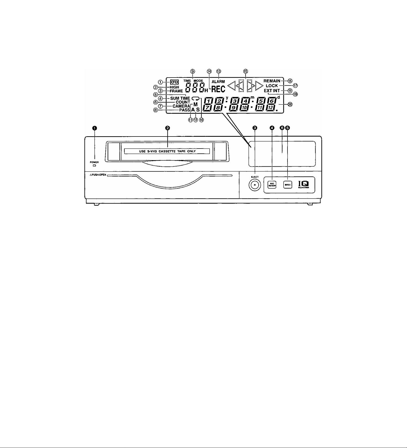
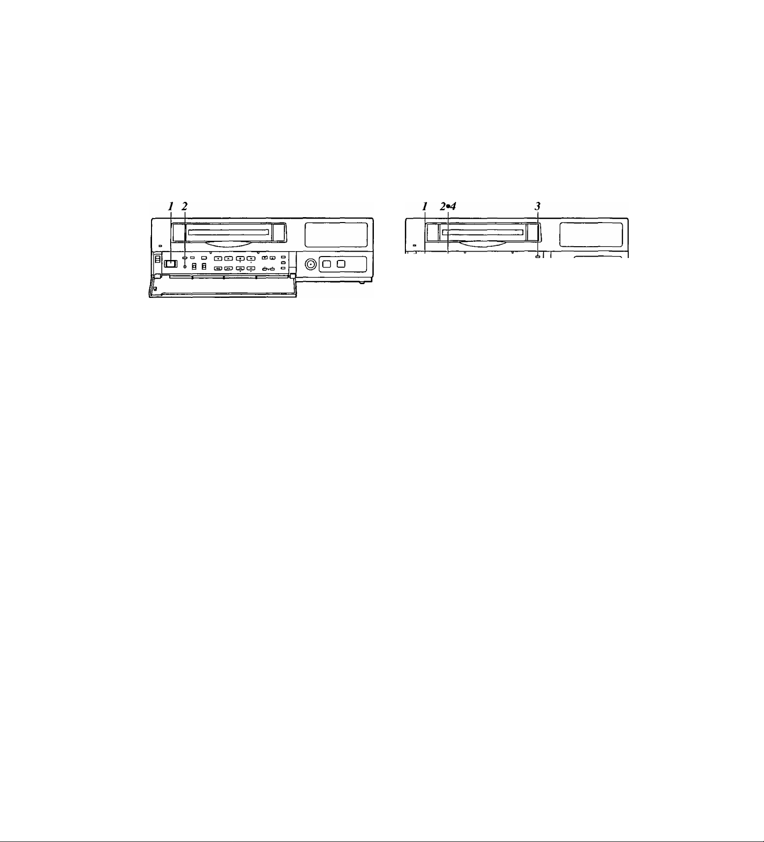
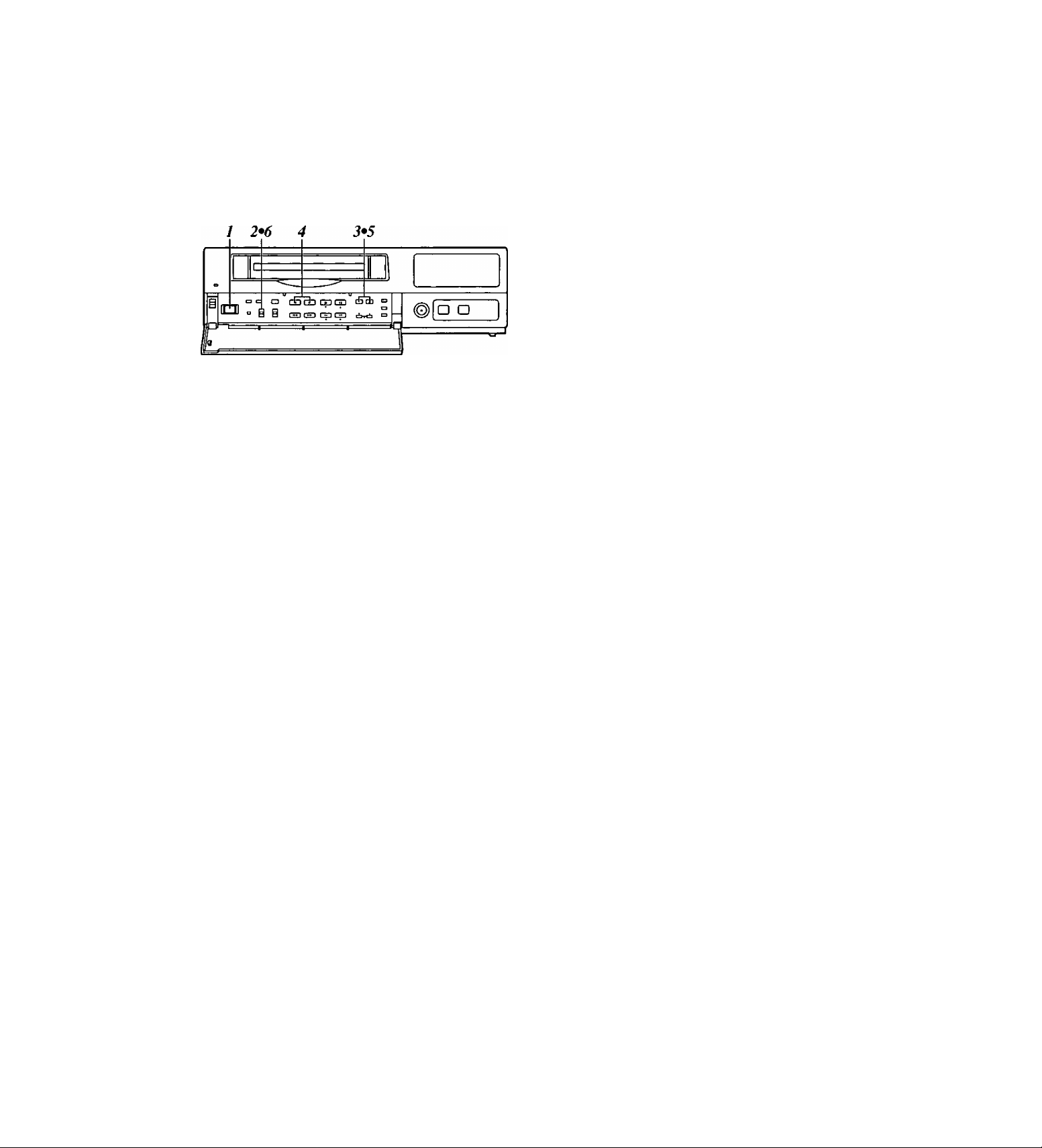
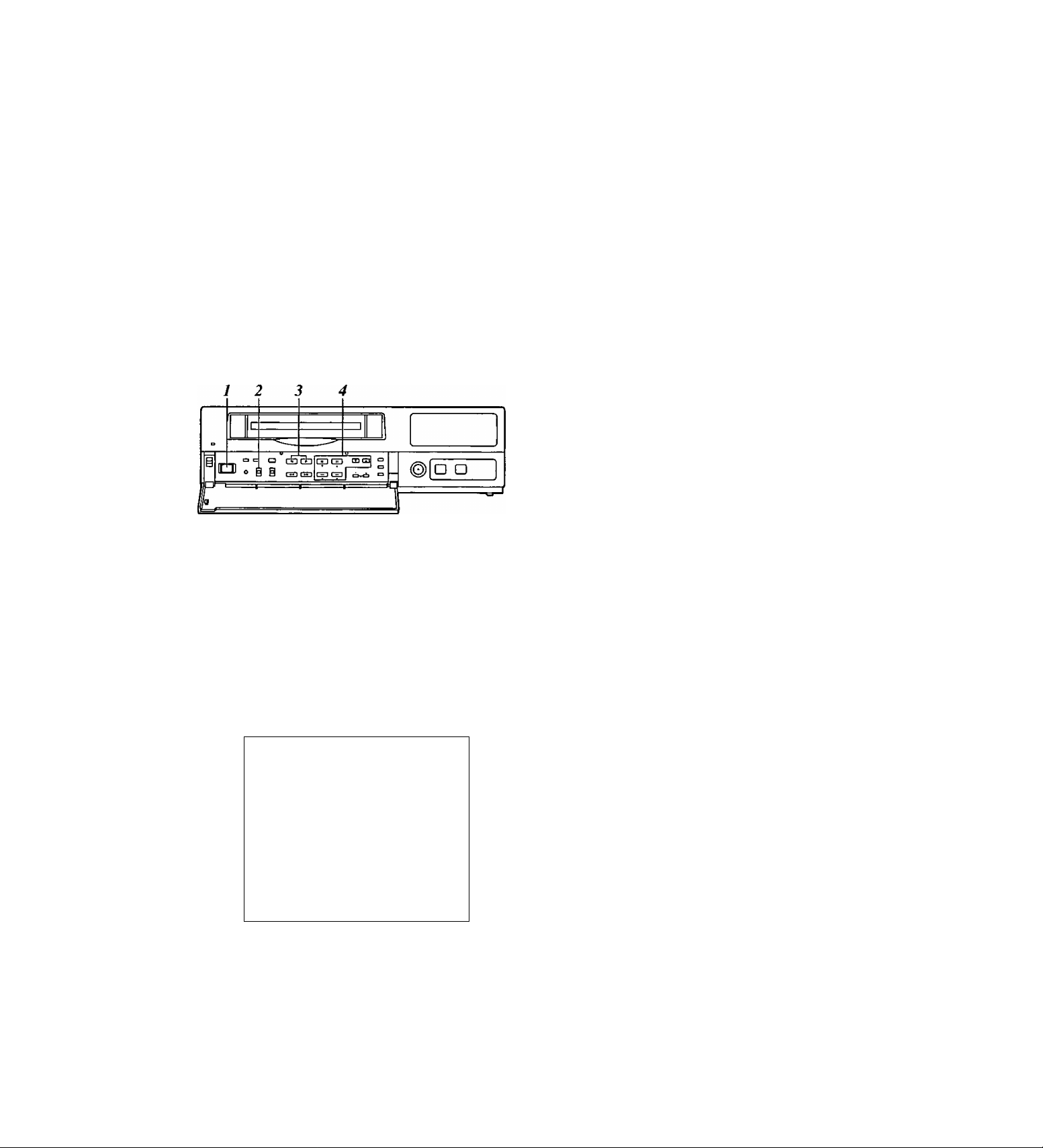
Parts and their functions
Front panel
o POWER lamp
This lights when the power is turned on.
©Cassette insertion slot
Always use S-VHS cassette tapes. If a VHS tape is
inserted instead, it will be automatically ejected
when the REC button is pressed. A cassette tape
will also be ejected when the REC button is
pressed if its accidental erasure prevention tab has
been broken out.
This unit is designed to provide the high level of
reliability required of a time lapse recorder for use
in such applications as surveillance, security and
monitoring.
In order to ensure that this unit will perform
reliably in recording operations, it is
recommended that the following Panasonic video
tape be used:
S-VHS tape: ST-120 series (120-minute tape)
©EJECT button
Press this to eject the cassette tape.
It will not work unless it is pressed firmly.
OREC REVIEW button
Press this during recording to monitor what is being
recorded. Several images captured a moment
before the button was pressed are played back,
and then the recording mode is restored.
It takes about 10 seconds for the playback picture
to appear.
0 REC button
Press this to start recording.
Page 6

Parts and their functions
O Display tube
®Ea
Lights when a cassette tape is inserted.
It flashes when an error is detected as a result of
the recording review.
©HIGH
Lights when a tape which was recorded in the
high picture quality mode is being played back
and when a tape is being recorded in the high
picture quality mode.
©FRAME
Lights when a tape which was recorded in the
frame mode is being played back and when a
tape is being recorded in the frame mode.
©SUM
Lights when the time is displayed in the summer
time (daylight saving) mode.
©TIME
Lights when the time is displayed.
©COUNT
Lights when the tape counter value is displayed.
©CAMERA
Lights when the camera number is displayed.
©REC
Lights during recording or rec-pause.
©Video operation mode displays
[> : Playback
: Reverse playback
REC : Recording, recording monitoring
REC QD : Rec-pause
DD ; Still picture (flashes during frame
playback), frame feed
OO : Fast forward, cue
<}<] : Rewind, review
©REMAIN
Flashes when the tape end is approaching (when
the remaining tape alarm mode has been set).
©LOCK
Lights when the lock mode has been set by the
LOCK switch or using the REC LOCK item on
the setting menu.
©EXT
Lights when the externa! timer mode has been
set.
©INT
Lights when the internal timer mode has been
set.
©PASS
Lights when the number of repeated tape
recordings (passes) is displayed.
©TIME MODE
Indicates the recording time mode.
©CD
Lights when repeat recording has been set.
©M
Lights when the memory stop mode has been
set.
©AS (S)
AS ; Lights when the alarm search mode has
been set.
S : Lights when the time search mode has
been set. The lamp flashes white a search
is in progress.
©ALARM
Lights during an alarm recording.
Flashes upon completion of the alarm recording.
©Counter display
Displays the time or tape counter value; displays
the error code when an error has occurred.
In addition, when a discrepancy has arisen
between the number of cameras set and the
number of cameras actually connected because
one of the cables connected to the CAMERA IN
connectors has been disconnected or loosened,
the camera number concerned will flash on the
display to warn the user.
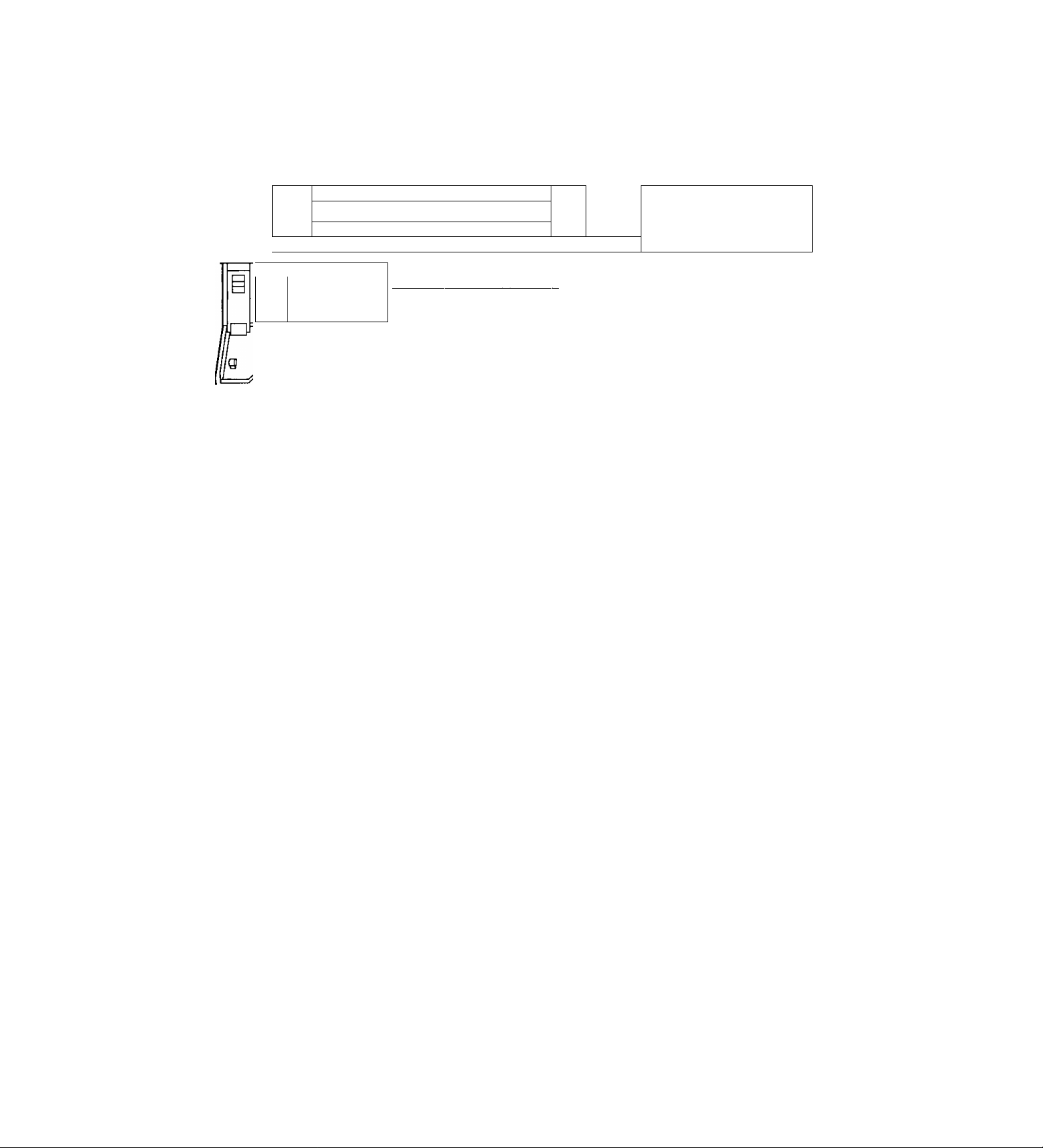
Page 7

Parts and their functions
Front panel (sub panel)
Q O O 000
SÊ S-VHÎ CASS ETTE TJ PE 0^
□
nucKMc ^
^ Tummoe
S P- □
„cnanm
Tss:—
"°~E3 0:;
hjiv «TO№ MusEjvru
GD ŒD Csli GD
— MGC + T à
Kcm El S Ff HcvAVD FWffAVD
CED CED CED
é m
O POWER switch
Used to turn the unit’s power ON and OFF.
When the power is turned on, the POWER lamp
lights, and the buzzer is sounded once.
OTRACKING buttons
Press during normal playback to adjust the tracking.
When these buttons are pressed during still-picture
playback, the unit is set to the field still-picture or
frame still-picture mode.
However, the unit will not be set to thé frame stillpicture mode if a tape recorded in the field mode
has been inserted.
OTIMER MODE button
Used to select the timer mode. Each time it is
pressed, the mode is changed, and one of the
following mode lamps lights on the display tube.
No display: Normal recording
EXT : External timer recording
INT : Internal timer recording
D
CAMEfU
¿□h
OuMTEft
CD-
lËAACn
a-
IQ
ŒD (ZD
cf>H±l
(DPLAY button
Press to play back the tape in the forward direction.
When the PROGRAM switch is at the MENU
position, this button functions as the PAGE (+)
button to select the setting menu screen.
When the PROGRAM switch is at the TIME ADJ
position, the button switches between the date
display and time display.
©STOP button
Press to stop the operation mode.
When the PROGRAM switch is at the MENU
position, this button functions as the SHIFT (T)
button to select the items on the setting menu
screen.
When the PROGRAM switch is at the TIME ADJ
position, the button moves the screen display
position downward.
®REV PLAY button
Press to play back the tape In the reverse direction.
When the PROGRAM switch is at the MENU
position, this button functions as the PAGE (-)
button to select the setting menu screen.
When the PROGRAM switch is at the TIME ADJ
position, the button switches between the date
display and time display.
Page 8

Parts and their functions
(E) PAUSE STILL button
Press to initiate rec-pause or still-picture playback.
When the unit remains in the pause or still-picture
playback mode for more than a prescribed period of
time, it is automatically set to the stop mode in
order to protect the tape.
When the PROGRAM switch is at the MENU
position, this button functions as the SHIFT (A)
button to select the items on the setting menu
screen.
When the PROGRAM switch is at the TIME ADJ
position, the button moves the screen display
position upward.
(ElTIME MODE buttons
Press to select the recording time mode.
3H : 3-hour recording mode
9H : 9-hour recording mode
12H : 12-hour recording mode
18H : 18-hour recording mode
24H : 24-hour recording mode
48H : 48-hour recording mode
72H : 72-hour recording mode
96H : 96-hour recording mode
120H : 120-hour recording mode
180H : 180-hour recording mode
240H : 240-hour recording mode
360H : 360-hour recording mode
480H : 480-hour recording mode
960H ; 960-hour recording mode
When the PROGRAM switch is at the MENU
position, these buttons function as the SET (-1-) and
(-) buttons to select the settings for the setting
menu items.
0 RESET button
Press while the counter value is shown on the
display tube by the COUNTER button to reset the
CTL counter.
When the camera number is shown on the display
tube by the COUNTER button during playback, this
button is used to switch the monitor screen
between 1 -screen playback and 4-screen playback.
(^COUNTER button
Used to switch the display mode on the display
tube.
Each time the COUNTER button is pressed, the
mode is switched as follows.
Camera number display:
The current camera number is displayed.
Clock display:
The current time is displayed.
IP:1H P
24-hour display
Counter display:
The tape counter is displayed.
_ n-
- u-
Pass display:
This indicates the number of times (passes) repeat
recording has been performed when repeat
recording has been set.
iZ£L22
SEARCH button
Press to select the search mode.
Each time this button is pressed in the counter
display mode, the search mode is switched, and
one of the following mode lamps lights on the
display tube:
M : Memory stop mode
AS : Alarm search mode
When the SEARCH button is pressed while the
time is displayed on the display tube by the
COUNTER button, the time search mode is set,
and “S” lights on the display tube.
0 :00 button
Press to set the seconds digits of the time to “00."
The seconds are reset to “00” when this button is
pressed while the display shows 0 to 29 seconds,
and they are carried up to 1 minute and set to “00”
when it is pressed while the display shows 30 to 59
seconds.
0 PROGRAM switch
Used to display the menu and adjust the time.
Keep this switch at OFF for normal operation.
MENU:
The setting menu screen is displayed.
When the switch is set to the MENU position
while holding down the STOP button, the alarm
screen or power loss screen appears.
TIME ADJ:
Set the switch to this position when adjusting the
time or adjusting the screen display position.
12-hour display
T t 9 m
m
Page 9
Parts and their functions
Front panel (sub panel)
ri--------------
1 USE S-VHS CASSETTE TAPE ONLY |
□
tWLCKMB ^
+ rutimwm
□ CD o
['jpnil 1
J ""O b:::
uu— —
fW PlAJ PUcr «T0»
[ -*■ I [ *• 1 I ■ 1 I ■■ 1
— P40C -4- f tflTT i
new 04 9 FT REVAVQ FWD MTft
[ »»-) { *iJ ■■!■)
(ZD IZD
- trr +
«T 9
CDb
^
___________________________________________
IQ
;
i!) O O Ci O
0LOCK switch
Used to set the lock mode.
ALL : All normal operations are suspended, and
LOCK lights on the display tube.
OFF : Normal operations can be conducted.
REC: Normal operations are suspended after
recording has commenced, and LOCK lights
on the display tube.
(REC REVIEW button operations are
acknowledged.)
® REW/0 button
Press in the stop mode to rewind the tape.
When this button is pressed during playback or stillpicture playback, the tape is reviewed.
® (HVFP button
Press in the stop mode to fast forward the tape.
When this button is pressed during playback or stillpicture playback, the tape is cued.
0REV AVD button
Press during still-picture playback to advance the
tape frame by frame in the reverse direction.
When the PROGRAM switch is at the MENU
position, this button serves as the SHIFT (◄)
button to select the setting menu screen items.
When the PROGRAM switch is at the TIME ADJ
position, the button moves the screen display
position toward the left.
é
0FWD AVD button
Press during still-picture playback to advance the
tape frame by frame in the forward direction.
When the PROGRAM switch is at the MENU
position, this button serves as the SHIFT (►)
button to select the setting menu screen items.
When the PROGRAM switch is at the TIME ADJ
position, the button moves the screen display
position toward the right.
0CAMERA buttons
In the playback mode:
Press during playback to select the camera and
play back the pictures recorded by the selected
camera.
In any other mode:
When the buttons are pressed in any other
mode, the camera to be monitored can be
selected.
When the [T] button and [A] button are pressed
together, the auto sequence mode is
established.
When they are pressed in the auto sequence
mode, the unit is switched to the manual
sequence mode.
Page 10
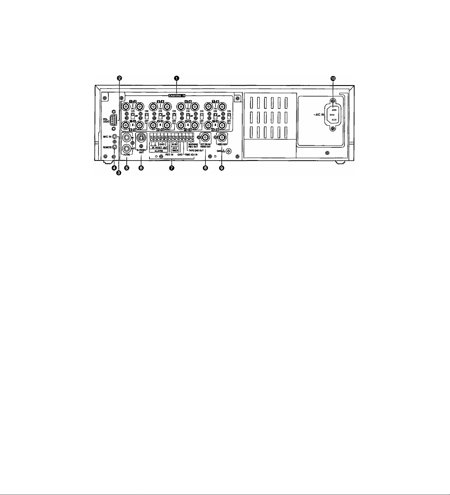
Parts and their functions
Rear panel
O CAMERA IN connectors []] to ^ (BNC),
75Q termination/loop through selector switches [Tj to 75Q termination switches to |i§
The camera and other external video input signals
(max. 16 inputs) are connected to these
connectors.
To use these connectors, select REC TYPE as the
RECORDING T-MODE & CAMERA setting on
menu screen P3.
<Note>
The 750 termination/loop through selector switches
[i] to ID have 3 positions.
Switches [U to [T| have 2 positions, 75 Q termination
ON and OFF.
0RS-232C connector
This is used to connect a personal computer or
other such device for controlling the unit.
0MIC IN jack (M3)
This is used to connect the audio input signals from
the microphone. (600n impedance)
©REMOTE connector
This is used to connect the model AG-A11 remote
controller available as an optional accessory.
©AUDIO connectors (pin jacks)
These are the audio input and output connectors.
When a microphone has been connected to the
MIC IN jack, the sound from this jack takes
precedence in recording.
OS-VIDEO OUT connector (4P)
This is used to connect the unit to a device
equipped with an S-video input connector.
OTerminal section
©EXT SWIN/VIDEO OUT connector (BNC)
The same video signals are output as the signals
from the VIDEO OUT connector ©. When EXT SW
IN is selected as the EXT SWITCHER MODE
setting on menu screen P7, the connector can be
made to serve as an input connector of the external
switcher.
©VIDEO OUT connector (BNC)
The video signals from the camera switched by the
internal sequential switcher are output from this
connector during recording.
During playback, the playback pictures of the
recorded tape are output.
The menu screen or time adjustment screen is also
displayed.
©AC IN socket
One end of the accessory power cord is connected
to this socket, and the other end is connected to a
household AC 120V power outlet.
10
Page 11
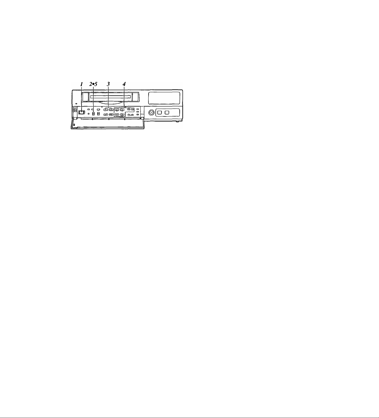
Performing initial settings
Before operating the unit, perform the following initial
settings.
■ Setting the date and time
X Set the power switch to ON.
Set the PROGRAM switch to the MENU position.
2
The setting menu screen is shown on the TV
monitor.
Press the PAGE (+) or PAGE {-) button to display
the P1 TIME/DATE PRESET screen.
The flashing items are ones that can be set.
PI
[TIME/DATE PRESET]
2000- 1-01 SAT
00:00:00
[REC LOCK]
MODE OFF
[HOUR METER]
OOOOOh
4 Proceed as follows to set the date and time.
• Use the (T) and (Á) SHIFT buttons to move the
flashing part to the item whose setting is to be
changed.
• Use the (◄) and (►) SHIFT buttons to move the
flashing part to the column where the setting is
to be changed.
• Press the (+) or (-) SET button to adjust the
figures.
5 upon completion of the settings, set the
PROGRAM switch to the OFF position.
The setting menu screen is cleared from the TV
monitor, and the normal mode is restored.
11
Page 12
Performing initial settings
If the clock is running fast or slow, follow the steps
below to adjust it.
■ Simple time adjustment
When the clock is running up to 30 seconds fast or
slow
1 Set the power switch to ON.
The second digits of the time are reset to “00”
2
when the 00: button is pressed in synchronization
with the time signal, etc.
They are reset to “00” when the button is pressed
while the display shows 0 to 29 seconds. They are
carried up to 1 minute and set to “00" when it is
pressed while the display shows 30 to 59 seconds.
When the clock is running up to 15 minutes fast or
slow
---
, o GDCDCDCXI CDCO
O O i g
□ D
X Set the power switch to ON.
2 Set the PROGRAM switch to the “adjust time”
position.
The counter display shows the current time, and
the “minutes" digits flash.
3 The minute and second digits of the time are reset
to “00:00” when the RESET button is pressed in
synchronization with the time signal, etc.
They are reset to “00:00” when the button is
pressed while the display shows 0 to 14 minutes.
They are carried up to 1 hour and set to “00.00”
when it is pressed while the display shows 45 to 59
minutes.
4 upon completion of the settings, set the
PROGRAM switch to the OFF position.
12
Page 13
Performing initial settings
If the date and time are wrong, follow the steps below
to adjust them,
■ Simple date and time adjustment
1 Set the power switch to ON.
2 Set the PROGRAM switch to the “adjust time"
position.
The counter display shows the current time, and
the “minutes” digits flash.
3 Press the SET (+) or SET (-) button to set the
“minutes" digits.
4 Press the PAGE {+) or PAGE {-) button.
The current date appears, and the “date" digits
flash.
5 Press the SET {+) or SET (-) button to set the
"date” digits.
^ Upon completion of the settings, set the
PROGRAM switch to the OFF position.
13
Page 14
Performing initial settings
Setting the recording time mode and
number of cameras
1 2*7 3*5 4*6
ICJ O É S
. o “cB^
P
1 Set the power switch to ON.
Set the PROGRAM switch to the MENU position.
2
The setting menu screen is shown on the TV
monitor.
Press the PAGE {+) or PAGE {-) button to display
the P3 RECORDING T-MODE & CAMERA screen.
The flashing items are ones that can be set.
Fixed at OFF.
The number of cameras to be used is
displayed automatically here.
Follow the steps below to set the recording time
mode and number of cameras.
• Use the (T), (A), (◄) and {►) SHIFT buttons
to move the flashing part to the item whose
setting is to be changed.
• Press the (+) and (-) SET buttons to change the
setting.
On the P3 RECORDING T-MODE & CAMERA
screen, set the number of cameras to be used and
their recording time modes for RTO through RT7 in
the REC TYPE column ahead of time.
Different kinds of recordings can be undertaken by
setting these two items when normal recording or
timer recording is to be performed.
<Notes>
• For RTO, T-MODE (recording time mode) is fixed
at OFF.
• For RT7, the setting for the number of cameras to
be used is fixed at 1 unit for C1.
[RECORDING T-MODE & CAMERA]
REC TTYPE M0(
RTO
RT1
RT2
RT3
RT4
RT5
RT6
RT7 [4 80H)l(Qt Cl ]
C.
16
*08
12H*04
24H*06
240H*10
120H*16
480H*12
Fixed at 01 Cl.
The recording time mode is set here.
(CAMERA SELECT)
ClC2C3
C4C5C6C7C8C9C10
Y Y
Y
Y Y N N N
Y Y Y N N
Y
Y Y Y Y Y
Y Y
Y
Y Y N
Y
Y Y Y
Y
Y
Y Y
Y Y
C13 CIS
C11
C12
C14 C16
Y Y Y
N
N
N
N
Y
Y
Y:YES N:N0
P3
N N
N N
N N .
N N
Y Y
N N
The cameras to be used are set here.
The cameras are set in pairs: C1-C2, C3-C4 and so on up to
C15-C16.
“Y” (YES) is set for each pair of cameras that is to be used.
A black burst signal (black screen) is recorded if no video
signals are supplied from a camera even when “Y” (YES)
has been set for that camera.
14
Page 15

Performing initial settings
Setting the recording mode
Press the PAGE {+) or PAGE (-) button to display
the P4 RECORDING MODE screen.
The flashing items are ones that can be set.
[RECORDING MODE]
FIELD/FRAME FIELD
PICTURE QUALITY
REC-TYPE RTO(OFF-+16)
[ALARM/SENSOR REC]
MODE OFF
FIELD/FRAME FIELD
PICTURE QUALITY
DURATION O.Smin
BUZZER OFF
REPEAT OFF
GROUP ALARM1
GROUP ALARMS RT0(OFF.+ 16}
HIGH
HIGH
RT0{OFF^:16)
P4
Set the recording mode by proceeding as follows.
• Use the (▼) and (A) SHIFT buttons to move the
flashing part to the item whose setting is to be
changed.
• Press the {+) and (-) SET buttons to change the
setting.
Upon completion of the settings, set the
PROGRAM switch to the OFF position.
The setting menu screen is cleared from the TV
monitor, and the normal mode is restored.
P4 RECORDING MODE screen
• Either field recording or frame recording is
selected for the FIELD/FRAME item setting.
• Either high-quality recording or standard quality
recording is selected for the PICTURE QUALITY
item setting.
• The recording time mode which was set on the P3
RECORDING T-MODE & CAMERA screen is
selected for the REC-TYPE setting.
When type RTO is selected, the recording time
mode which was set using the TIME MODE
button on the front panel is used for recording.
When a type from RT1 to RT7 is selected, the
recording time mode which was set by RT1 to
RT7 is used for recording.
<Notes>
• When RT7 is selected for the REC-TYPE item
setting, frame recording will be forcibly performed
regardless of the FIELD/FRAME item setting.
• Recording is possible at 60 fields a second (which
is the same rate as for video machines used in the
home) if NORMAL is selected as the PICTURE
QUALITY item setting and the recording time
mode is set to 3H when RT7 has been selected
as the REC-TYPE item setting.
• If the recording time mode is set to 3H when a
setting other than RT7 has been selected for the
REC-TYPE item, recording will be performed
automatically in the high picture quality mode
regardless of the PICTURE QUALITY item
setting.
15
Page 16

Performing initial settings
The table below shows the correlation between the recording time modes and number of cameras.
(When an S-VHS 120-minute tape is used)
Set the modes according to what is to be accomplished.
High picture quality mode (field recording)
Time taken for recording turn to circuiate and return to the first camera
for the no. of cameras connected
2
cameras
0.033 0.07
0.233
0.300 0.60
1.100 2.20
2.700 5.40
cameras6cameras
0.20 0.40 0.60
0.33
0.47
1.13
2.73
10.80 16.20 21.60
16.13 24.20 32.27
10.73
21.47
42.80 64.20 85.60
Recording
time mode
3H
9H
12H
18H
24H
48H
72H
96H
120H
180H
240H
360H
480H
960H
No. of fields
to be
recorded
per sec.
Time taken to
switch
cameras (sec.)
30.00
10.00 0.100
6.00 0.167
4.29
3.33
1.76 0.567
1.20 0.833 1.67
0.91
0.73 1.367
0.49 2.033 4.07
0.37
0.25 4.033 8.07
0.19 5.367
0.09
10.700 21.40
Standard picture quaiity mode (field recording)
4
0.13 0.20 0.27
0.67
0.93
1.20 1.80 2.40
2.27
3.33 5.00 6.67
4.40
5.47
8.13 12.20 16.27
1.00 1.33
1.40
3.40 4.53
6.60 8.80
8.20
32.20 42.93
8
cameras
0.80
1.87
10.93
10
cameras12cameras
0.33 0.40 0.47
1.00 1.20
1.67
2.33
3.00 3.60 4.20
5.67
8.33 10.00 11.67
11.00 13.20
13.67
20.33 24.40 28.47
27.00
40.33 48.40
53.67 64.40
107.00 128.40 149.80
cameras
2.00 2.33
2.80
6.80 7.93
.16.40 19.13
32.40 37.80
14
1.40
3.27
15.40
56.47
75.13
16
cameras
0.53
1.60
2.67
3.73
4.80
9.07
13.33
17.60
21.87
32.53
43.20
64.53
85.87
171.20
No. of fields
Recording
time mode
3H
9H
12H
18H
24H
48H
72H
96H
120H
1B0H
240H
360H
480H
960H
<Notes>
• The actual recording time will be slightly longer than the figure indicated by the recording time mode.
• In the frame recording mode, it takes twice as long for the cameras to be switched.
• When the recording time mode is set to 3H, recording will be performed automatically in the high picture quality mode even
if the standard picture quality mode has been set.
to be
recorded
per sec.
Time taken to
switch
cameras (sec.)
30.00 0.033 0.07
20.00 0.050
12.00
8.57
6.67
3.53
2.40 0.417
1.82 0.550
1.46
0.98 1.017
0.74
0.50 2.017
0.37
0.19 5.350
Time taken for recording turn to circuiate and return to the first camera
for the no. of cameras connected
2
cameras
0,10
0.083 0.17
0.117 0.23
0.150
0.283 0.57
0.683 1.37
1.350 2.70
2.683 5.37
0.30
0.83
1.10
2.03
4.03
10.70
4
cameras6cameras
0.13
0.20 0.30
0.33 0.50 0.67
0.47
0.60 0.90 1.20
1.13 1.70 2.27
1.67
2.20 3.30
2.73
4.07 6.10
5.40 8.10 10.80
8.07
10.73 16.10 21.47
21.40 32.10 42.80
cameras
0.20 0.27
0.70 0.93
2.50 3.33
4.10 5.47
12.10 16.13
8
0.40
4.40
8.13
10
cameras12cameras
0.33 0.40 0.47
0.50 0.60 0.70
0.83
1.17 1.40
1.50 1.80 2.10
2.83 3.40 3.97
4.17
5.50 6.60
6.83 8.20 9.57
10.17 12.20
13.50 16.20
20.17 24.20
26.83 32.20 37.57
53.50
cameras
1.00
5.00 5.83
64.20 74.90
14
1.17
1.63
7.70
14.23
18.90
28.23
16
cameras
10.93
16.27
21.60
32.27
42.93
85.60
0.53
0.80
1.33
1.87
2.40
4.53
6.67
8.80
16
Page 17
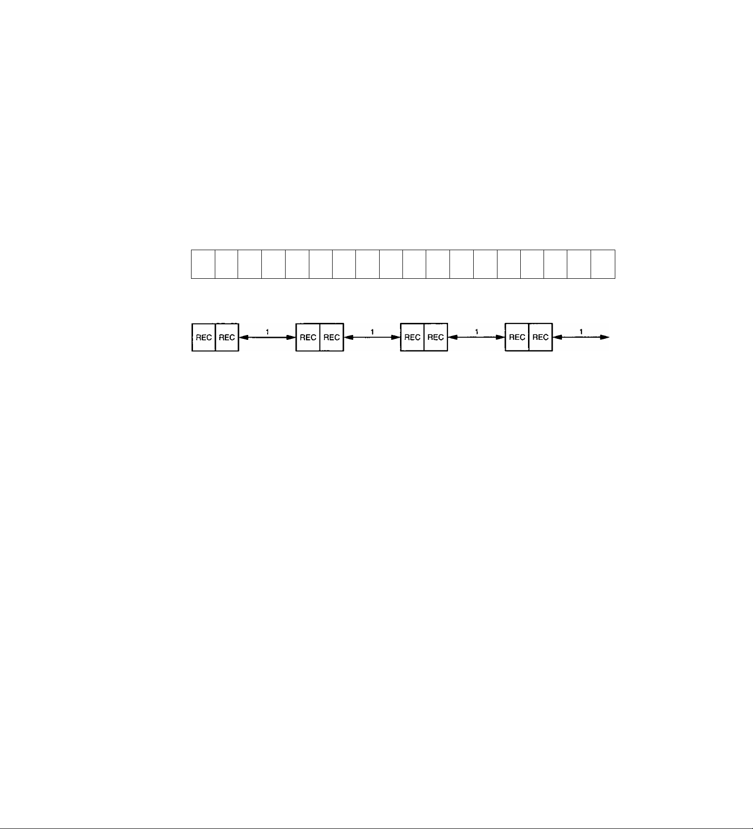
Frame recording and field recording
With frame recording, the image of one camera is
recorded in two fields, and after leaving a fixed
interval, the image of the next camera is recorded.
With field recording, the image of one camera is
recorded in one field, and after leaving half of the
interval for frame recording, the image of the next
camera is recorded.
The gaps between the recorded images are shorter
which enables the cameras to be switched in half the
time taken by frame recording.
Example where cameras 1 to 4 are connected
Actual image
Frame
recording
Field
recording
A B C D E
Camera
No.1
Camera
No.1
REC
1/2
Camera
No.2
REC
1/2
Camera
No.2
Camera
No.3
REC
1/2
N
Camera
No.4
Camera
No.3
REC
0 P Q
Camera
No.4
1/2
REC
F
1/2
H 1 J K L M
G
Camera
No.3
Camera
No.4
REC
1/2
Camera
No.1
REC
1/2
Camera
No.2
REC
R
1/2
17
Page 18
Connections
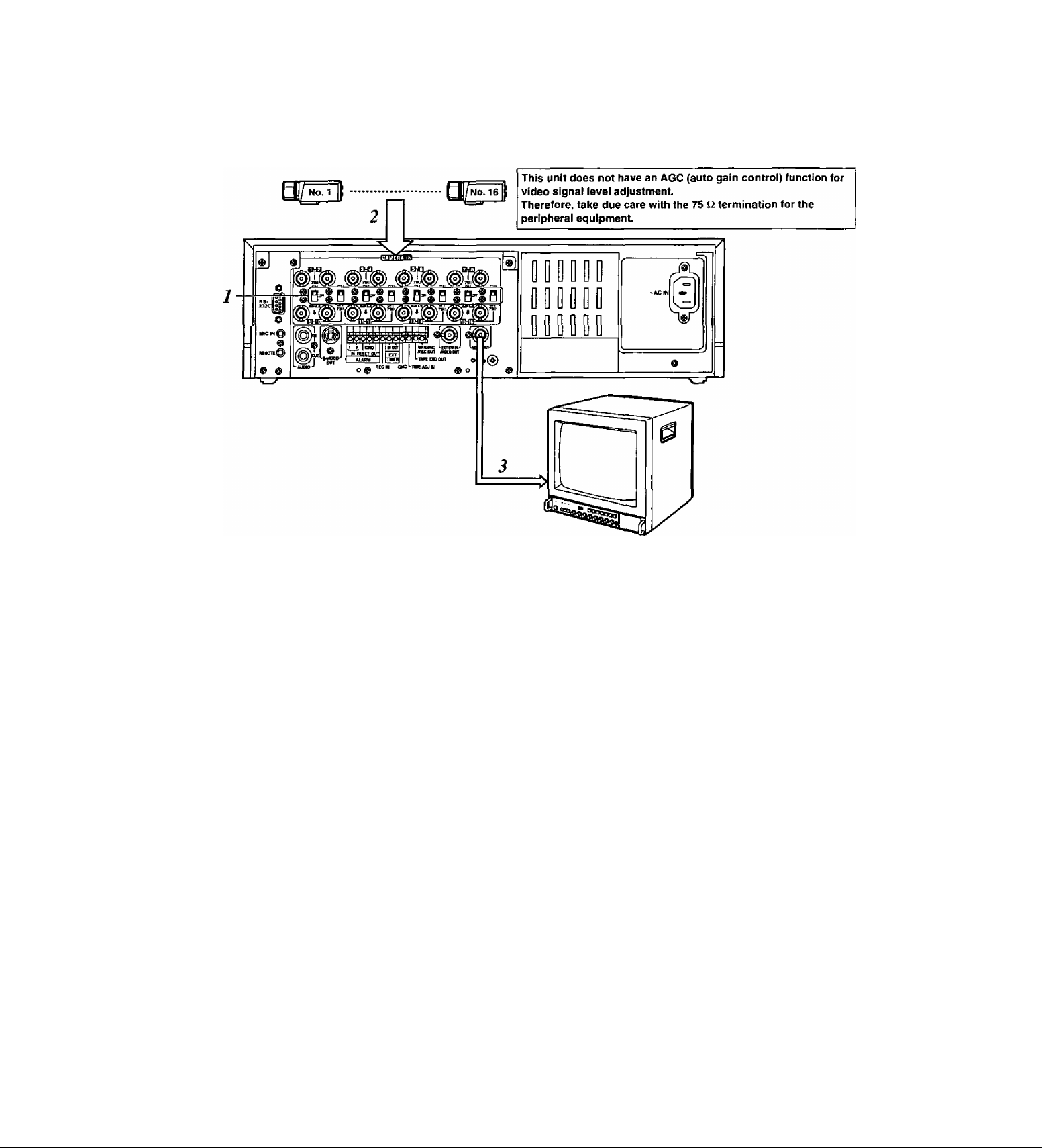
Example of connections to switch between 16 cameras for recording
2 Set all 8 of the 75 Q termination switches to the
ON position.
2 Connect the 16 cameras to CAMERA IN
connectors [T] to [i6|.
3 Connect the TV monitor to the VIDEO OUT
connector.
<Notes>
• When connecting line-locked cameras, select ON
for the LL CAMERA item setting on the setting
menu shown on the P7 VIDEO OUT SEQUENCE
screen.
The images on the monitor will shake fractionally:
this is normal and not indicative of malfunctioning.
• This unit does not contain a compensation circuit.
Install a compensator when the total length of the
cables (coaxial 3C-2V) used to connect the
cameras exceeds 200 meters.
There is no need to install a compensator if the total
length is under 400 meters if coaxial cables (5C-2V)
with minimal transmission loss are used.
18
Page 19
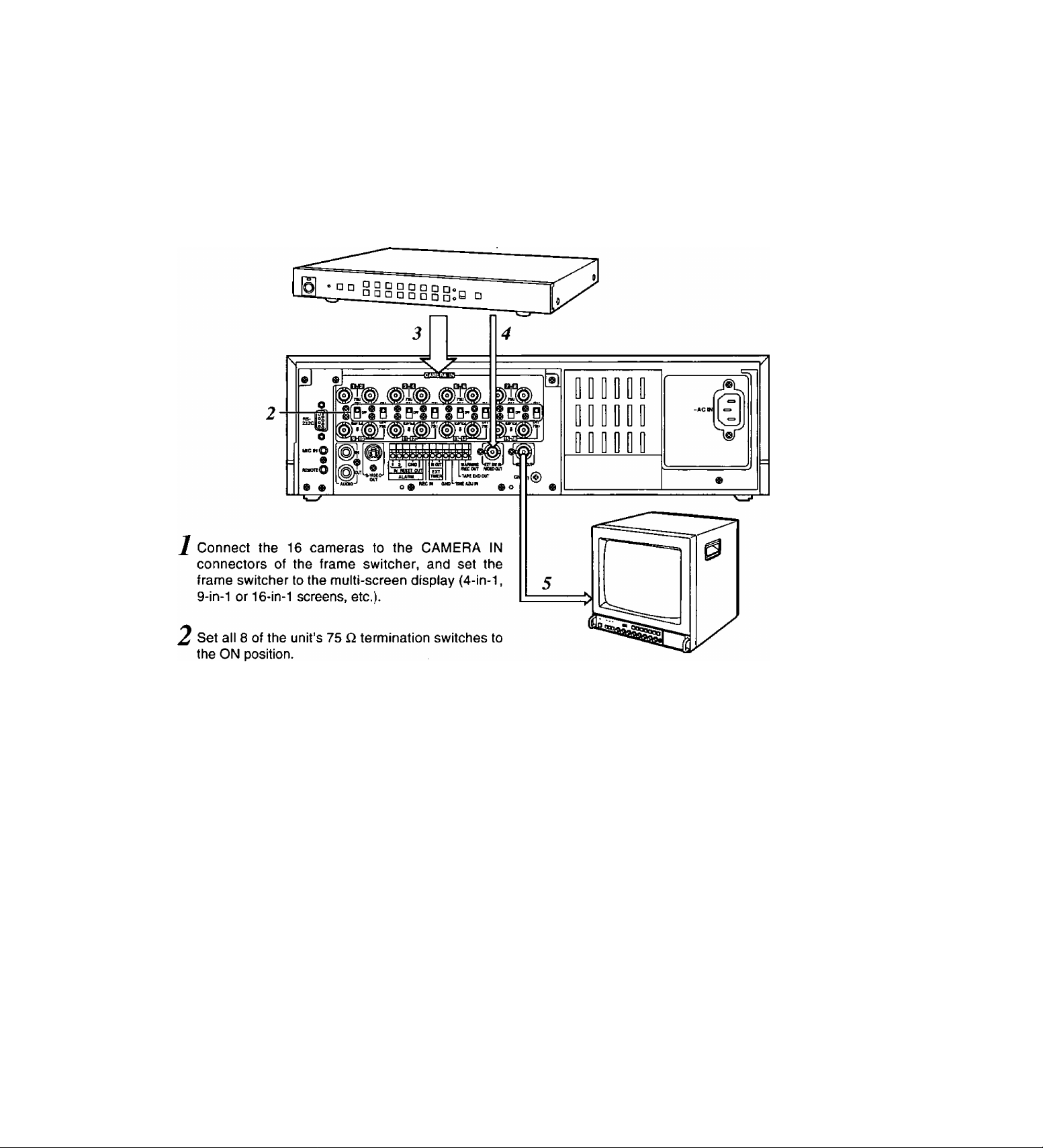
Connections
When using a frame switcher during recording to output more than one screen image on the TV monitor
....
Connect the 16 camera outputs of the frame
switcher to CAMERA IN connectors [T] through [i^
on the unit.
Connect the video output of the frame switcher to
4
the EXT SW INA/IDEO OUT connector on the unit.
Connect the TV monitor to the VIDEO OUT
5
connector on the unit.
Select EXT SW IN as the MODE item setting on
6
the setting menu shown on the P7 EXT
SWITCHER screen.
The multiple images set by the frame switcher can
be viewed on the TV monitor in all modes except
for the playback mode.
19
Page 20
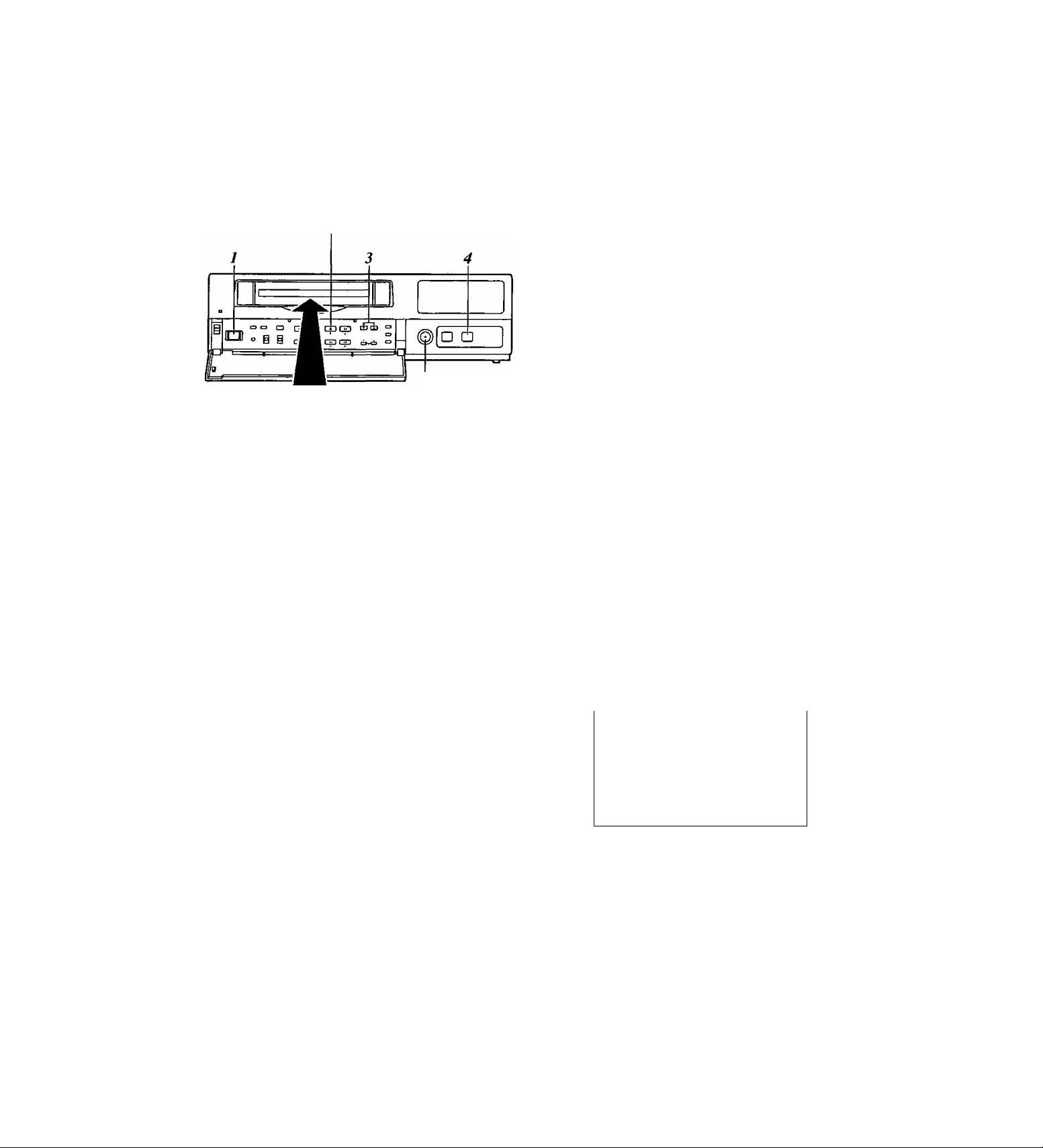
Recording
Proceed with recording after having performed the
connections and followed the steps for “Setting the
date and time” (page 11) and “Setting the recording
time mode and number of cameras” (page 14).
STOP button
EJECT button
/C31ZZ1E3
Set the power switch to ON.
When the power is turned on, the POWER lamp
lights, and the buzzer is sounded once.
Insert the cassette tape.
Press the EJECT button to eject the cassette tape.
It will not work unless it is pressed firmly.
<Note>
Always use S-VHS cassette tapes. If a VMS tape
is inserted instead, it will be automatically ejected
when the REC button is pressed.
A cassette tape will also be ejected when the REC
button is pressed if its accidental erasure
prevention tab has been broken out.
This unit is designed to provide the high level of
reliability required of a time lapse recorder for use
in such applications as surveillance, security and
monitoring.
In order to ensure that this unit will perform
reliably in recording operations, it is
recommended that the following Panasonic video
tape be used;
S-VHS tape: ST-120 series (120-minute tape)
Press the TIME MODE buttons to set the recording
time mode.
Press the REC button.
Recording is started in the set time mode using the
set cameras which are switched in turn
automatically.
To stop the recording, press the STOP button.
When 8 cameras are to be used, select “N” (NO) for
C9—C16 in the RTO camera setting columns
(CAMERA SELECT) on the setting menu shown on
the P3 RECORDING T-MODE & CAMERA screen.
[RECORDING T-MODE & CAMERA] P3
REC T- C.
TYPE MODE NO
RTO OFF+ 8
RT1
OFF+ 16
RT2
OFF+ 16
OFF^t; 16
RT3
RT4
OFF+ 16 y Y Y Y Y Y Y Y
OFF^ 16
RT5
OFF+ 16
RT6
RT7 OFF* 01
(CAMERA SELECT)
C1C3C5C7 C9C11C13C15
C2 C4 C6 C8 CIO C12 C14 C16
Y Y Y
Y Y Y Y Y
Y Y Y Y
Y Y Y Y Y Y Y Y
Y Y Y
Y Y Y Y
Cl
Y N N N N
Y Y Y
Y Y Y Y
Y Y y Y Y
Y Y Y Y
Y:YES N:NO
When recording always in the same recording time
mode instead of setting the mode using the TIME
MODE button, set RT1 through RT7 for the REC
TYPE item on the setting menu shown on the P3
RECORDING T-MODE & CAMERA screen, and set
the REC TYPE (RT1 through RT7) to be used for
recording for the REC-TYPE item on the P4
RECORDING MODE screen.
Select RT7 when using one camera for the
recording. This enables the images of the camera
connected to the camera input [i] connector to be
recorded.
20
Page 21
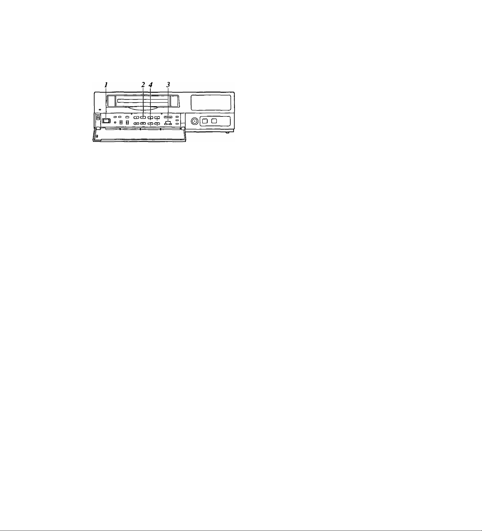
Playback
Normal playback
Set the power switch to ON, and insert the
cassette tape.
Press the PLAY button to start playback.
When 8 cameras are being used, the 8 camera
numbers appear on the camera number display of
the display tube, and the number of the camera
whose pictures are being played back is enclosed
in a square.
2 3 A 5 9
Still-picture playback
2»4 3
ra a □ GDQDGDciJ
(Cl o g i
r
C53 CHI CD GD tbrii ■=>
iL
1 Set the power switch to ON, and insert the
cassette tape.
2 Press the PLAY button to start playback.
3 Press the PAUSE STILL button.
The unit is now set to the still-picture playback
mode.
(When the frame advance button is pressed in the
still-picture playback mode, the tape is played back
one frame at a time.)
o □
3 Press the CAMERA buttons to set the playback
camera.
^ To stop the playback, press the STOP button.
<Note>
When video noise in blocks interferes with playback,
press the (+) or {-) tracking button until the noise is
eliminated.
4 Press the PLAY button again to return to normal
playback.
5 To stop the playback, press the STOP button.
<Note>
If a switch is made to cameras No.13 to 16 when a
tape which was fra me-recorded using cameras No.13
to 16 is being played back in the still-picture playback
mode, blue background signals will be output.
21
Page 22
Changing over the screen display
Changing over the screen during playback
COUNTER button
RESET button
IL
cao □ CZJCDCpQD ra P| _
° § i OCHDtpS ip^ c!
SEARCH button
CAMERA button
□ a
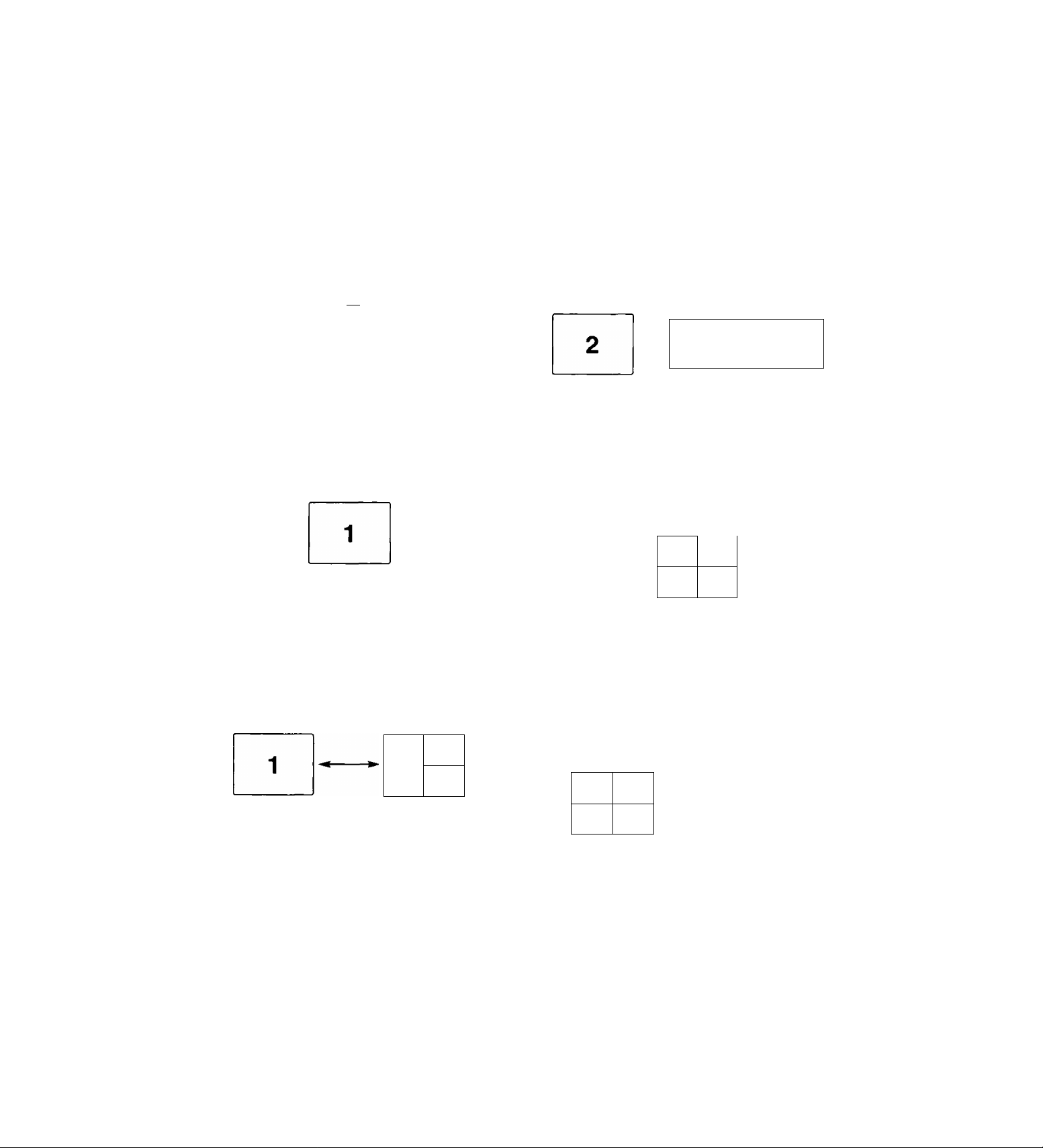
Changing between the 1-screen and 4-in-1
screen display
X During playback, one screen is displayed on the
TV monitor.
Press the COUNTER button to establish the
2
camera number display mode.
Press the RESET button to change over to the 4-
3
in-1 screen display.
Each time the RESET button is now pressed, the
display is switched between the 1-screen and 4-in-
1 screen.
«2
1 cot
CM
4
3“
CAUER* 7 3 O to 11 12
Switching between the cameras
In the 1-screen display mode
The pictures recorded by a specific camera can be
monitored by pressing the CAMERA button during
playback.
CAIIERA
1 ilW^i
T B O 1Ù
s a
If 12
3 4
In the 4-in-1 screen display mode
When monitoring the pictures recorded by specific
cameras on the four screens in the 4-in-1 screen
display mode
X Press the SEARCH button to move to the screen
with the white border.
1 cot
C03
“4
3
2 Press the CAMERA button to set the camera.
(3& ©0 ® ®
7 3 9 to 11 12
Repeat steps 1 and 2 for the other screens to set
the camera for each.
co:2
^ cm
C033C0£
6
0© © -* S
7 3 9 10 11 12
Four camera numbers are enclosed in squares on the
camera number display of the display tube, and the
square corresponding to the number of the selected
camera flashes. In addition, the numbers of the
cameras (C01/C02/C03/C04) appear in the center of
the TV monitor.
<Note>
It is not possible to switch to the 4-in-1 screen display
when a tape which was frame-recorded using
cameras No.13 to 16 is to be played back.
22
Page 23
Useful functions
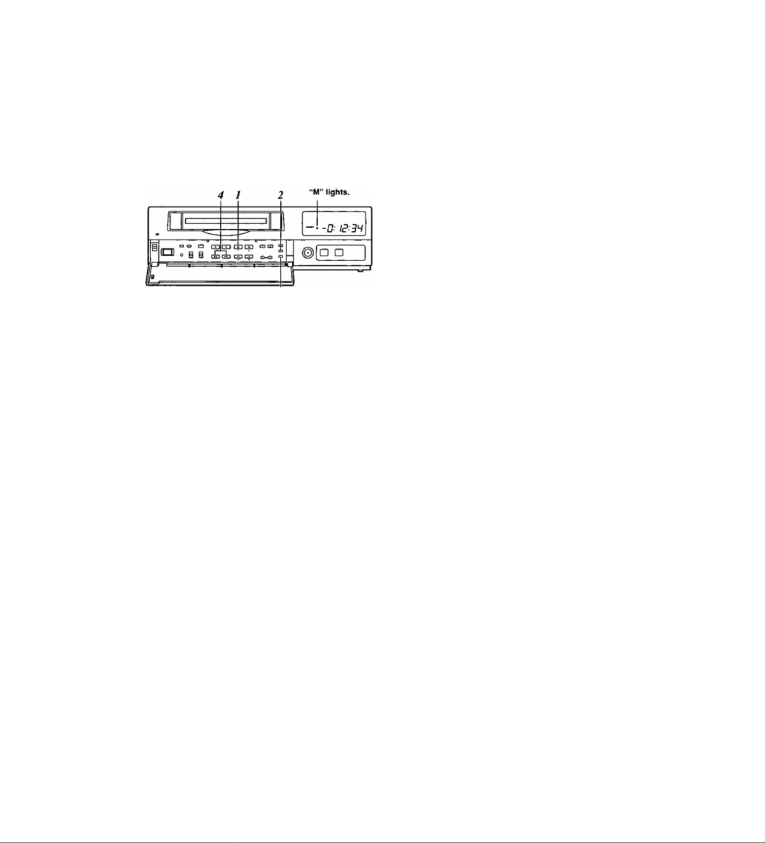
Memory stop
This function serves to rewind or fast forward the tape
to the “00:00:00” counter position and then
automatically set the unit to the stop mode when a
regular operation is being performed.
J Press the STOP button to set the unit to the stop
mode.
2 Press the COUNTER button to establish the
counter display mode.
3 Press the SEARCH button.
Check that “M” lights on the display tube and that
the memory stop mode is established.
Press the SEARCH button again if “AS” has
lighted.
4 Press the REW button if the counter reading is
higher than “00:00:00”; conversely, press the FF
button if it is lower (a negative value) than
“00:00:00.”
5 The counter reading approaches “00:00:00,” and
the tape is automatically set to the stop mode.
23
Page 24
Useful functions
Alarm recording and sensor (emergency) recording
Alarm recording
This function enables recording with changes made to
the time mode and/or cameras used for recording
when an alarm signal (see page 35 for details on the
alarm recording connections) is input during
recording.
Sensor (emergency) recording
This function enables recording with changes made to
the time mode and/or cameras used for recording as
soon as an alarm signal is input even when the unit’s
power is off.
Set the POWER switch to ON, and insert the
cassette tape.
Take the following steps to set the recording mode
to be established when an alarm signal is input:
• Use the (▼) and (▲) SHIFT buttons to move the
flashing part to the item whose setting is to be
changed.
• Press the (+) and {-) SET buttons, and change
the setting.
<Notes>
• Alarm recording and sensor recording are
selected using the MODE item.
Select OFF as the MODE item setting if
recording is not to be performed when an alarm
signal is input.
• The recording time (DURATION) is set as
follows between 30 seconds and 10 minutes:
CONTINUE (up to the tape-end) or MANUAL
(while the alarm signal is input).
When the settings are completed, set the
PROGRAM switch to the OFF position.
The setting menu screen is cleared from the TV
monitor, and the normal mode is restored.
Set the PROGRAM switch to the MENU position.
The setting menu screen now appears on the TV
monitor.
Press the PAGE (+) or PAGE (-) button to display
the P4 ALARM/SENSOR REC screen.
The flashing items are ones that can be set.
(RECORDING MODE)
FIELD/FRAME
PICTURE QUALITY
REC-TYPE RT0(OFF*16)
[ALARM/SENSOR REC]
MODE
FIELD/FRAME
PICTURE QUALITY HIGH
DURATION
BUZZER
REPEAT
GROUP ALARM1 RT0(OFF+16)
GROUP ALARM2
FIELD
HIGH
OFF
FIELD
0.5mm
OFF
OFF
RT0(OFF*16)
P4
24
Page 25

Useful functions
When ALARM is selected as the MODE item
setting
Press the REC button to start recording.
The alarm recording mode is established when an
alarm signal is input.
Once alarm recording is initiated, “ALARM” flashes on
the display tube.
When the STOP button is pressed, the display is
cleared, and recording stops.
• When OFF or SENSOR is selected as the MODE
setting on the menu screen shown on P4
ALARM/SENSOR REC, the alarm recording
function does not work.
Alarm signal input
♦
Recording
Alarm
recording
Recording
time
(DURATION)
* »1
Recording proceeds in the alarm
recording mode which has been set.
Recording
When SENSOR is selected as the MODE item
setting
Sensor recording starts as soon as an alarm signal is
input even when the unit’s power is off or the tape has
stopped.
• When OFF or ALARM is selected as the MODE
setting on the menu screen shown on P4
ALARM/SENSOR REC, the sensor recording
function does not work.
Alarm signal input
♦
Sensor
recording
y
The power is off or
the tape is stopped
or in the internal
Recording
time
(DURATION)
Recording proceeds in the sensor
recording mode which has been set.
The power is off or
the tape is stopped
or in the internal
<Note>
When sensor recording is completed, the operation
prior to the alarm signal input is restored.
<Note>
When alarm recording is completed, the operation
prior to the alarm signal input is restored.
When ALARM/SENSOR is selected as the MODE
item setting
Both alarm recording and sensor recording are
performed.
If an alarm signal is input during recording, the alarm
recording mode is established, and when it is input
while the unit’s power is off or the tape has stopped,
sensor recording is started.
25
Page 26
Useful functions
Alarm memory recall and power loss memory recall
Alarm memory recall is a function for storing in the
memory those dates/times and number of occasions
on which the alarm recording and sensor recording
functions were activated.
Power loss memory recall is a function for storing in
the memory those dates/times and number of
occasions on which the primary power supply was
shut off due to a power outage, etc.
J Set the POWER switch to ON.
Set the PROGRAM switch to the MENU position
2
while holding down the STOP button.
The ALARM RECALL screen and POWER LOSS
MEMORY screen now appear.
The alarm number/s and dates/times when the
alarm signal was input are displayed on the
ALARM RECALL screen.
The number of times the primary power source has
been shut off and the dates/times when this
happened are displayed on the POWER LOSS
MEMORY screen.
(Data is displayed in sequence with the latest at
the top of the screen.)
The following display appears when alarm recording
was never performed or when the primary power
supply was never shut off.
[ALARM RECALL]
■++-4;-f- 4=4;
4^ 4-—4 4—4 4 4 4
4; 4-—4 4—4 4 44
44—44—444 4
44—4 4—4 4 44
[POWER LOSS MEMORY]
44—44—4444 44:44
>f; rf: 44—44—44 44 4 4:4 4
44 4 4"—4 4—4 4 44 4 : 4 4
4 4:44
4 4:44
4 4:44
4 4:4 :f4 4:4 4
4^::41-
4 4:44
4 4:44
<Notes>
• Data for up to 8 alarms is stored on the ALARM
RECALL screen whereas data for up to 4 power
losses is stored on the POWER LOSS MEMORY
screen.
• A total of 99 alarms and 99 power tosses are stored
in the memory.
When 99 is exceeded, the count returns to “00.”
• As with alarm recordings, the sensor recordings are
stored as alarm memory data.
• The alarm memory data and power loss memory
data are stored in the memory circuit inside the unit.
They are not recorded on the tape.
• When the PROGRAM switch is set to any position
except MENU, the ALARM RECALL screen and
POWER LOSS MEMORY screen displays are
cleared.
• When the RESET button is pressed while the
ALARM RECALL screen is displayed, the memory
can be cleared, but the POWER LOSS MEMORY
screen is not cleared.
[ALARM RECALL]
44 44_44_4444 44:4 4
RECALL]
[ALARM
12 - 30 - 2000
29
12 - 04 - 2000
28
27
10 - 25 - 2000
9 - 10 - 2000
26
8 - 11 - 2000
25
24
5- 10-2000
4 - 11 - 2000
23
22
3- 10-2000
[POWER LOSS MEMORY]
14
12 - 01 -2000
10 - 05 - 2000
13
12 08- 10 - 2000 9:20
11
3-02-2000
3:15
12:10
2:20
2:30
6:55
3:22
6:55
3:22
12:00
10:30
7:00
26
4 4 4 4—4 4—4 4 4 4
'f’^ ^ ^ ^
44 44—44—4444
44 4>f:_4:ir_4444
44 44-44-4444
[POWER LOSS MEMORY]
14 12-01-2000 12:00
13 10-05-2000
12 08-10 - 2000
11 3 - 02 - 2000
44:44
4.-(^:4 4
4 4;;(;4
10:30
9:20
7:00
Page 27

Useful functions
Search playback (cue/review)
o □ O GDCDCpGD cam
@ @ C3 ^ CS CS eK<S
X Set the POWER switch to ON, and insert the
cassette tape.
2 Press the PLAY button to start playback.
3 Press the FF button or REW button.
The unit performs search playback (cue or review)
while the FF button or REW button is held down.
Normal playback is restored when the FF button or
REW button is released.
<Notes>
• When search playback is performed with a tape
which was fra me-recorded using cameras No. 13 to
16, the recorded images of all the cameras are
mixed and output even if a particular camera is
selected.
• The picture will become quite blurred when search
playback is performed for a tape which was field-
recorded in the standard picture quality mode. This
is normal and not indicative of malfunctioning.
□ D
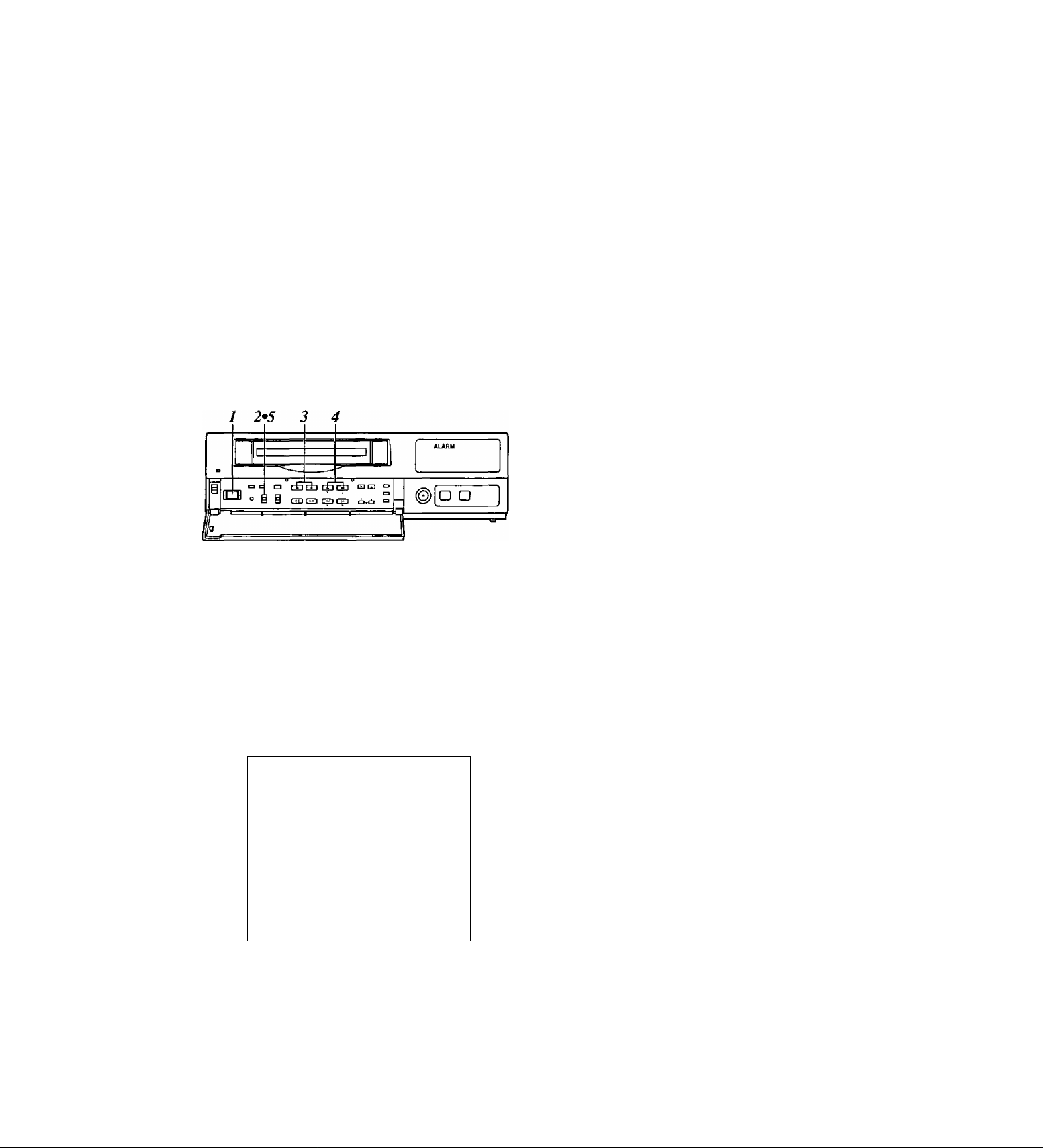
Alarm search
(alarm recording section search)
c 7 “AS” lights.
»-a
= = a El GH GH GD rara
o
° @ @ tH3(H3CSDC3
30
D □
2 Set the POWER switch to ON, and insert the
cassette tape containing the alarm recording.
2 Press the COUNTER button to establish the
counter display mode.
3 Press the SEARCH button.
Check that “AS” lights on the display tube and that
the alarm search mode is established.
Press the SEARCH button again if “M” has lighted.
4 While the unit is in the stop, fast forward or rewind
mode, press the REW or FF button.
The first alarm recording section is searched in the
direction corresponding to the button pressed, and
the unit is set to the still-picture playback mode.
5 To play back the section, press the PLAY button.
<Notes>
• To release the alarm search mode, press the
SEARCH button again to clear “AS" from the
display tube.
• The alarm search function can be used to search
for only those alarm recording sections which were
recorded for more than 30 seconds in the 3-hour, 9hour, 12-hour, 18-hour or 24-hour recording time
mode.
• When the FF button or REW button is pressed
during playback, search playback (cue or review) is
initiated, and even when the button is released,
search playback will continue if the unit is in the
alarm search mode.
27
Page 28

Useful functions
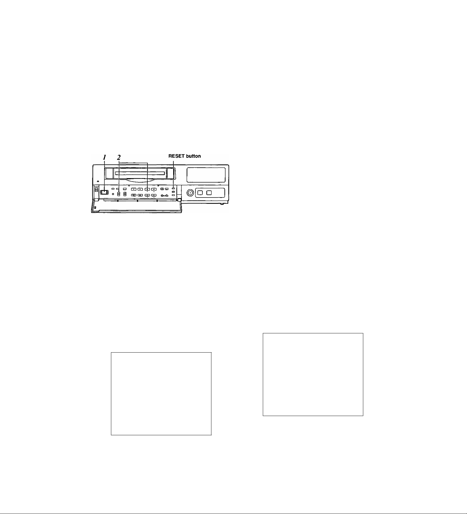
Time/date search
This function is used to search for a particular
recording section by designating its date and time.
RESET button
5 4
I => •=> O GDGDGDtZD tutu =
Dogs d«
“S” lights.
-
□ D
-------------
^
3 2
2 Set the POWER switch to ON, and insert the
cassette tape.
2 Press the COUNTER button to establish the time
display mode.
3 Press the SEARCH button.
“S” lights on the display tube, and the TIME DATE
SEARCH screen appears on the TV monitor.
Press the PLAY button or REV PLAY button.
The recording section with the designated date and
time is now searched.
<Notes>
• The tape comes to a stop at its end or start if no
recording section with the date and time was
found as a result of the search.
• When the tape is stopped during recording, it
will stop at the border between the new
recording and old recording, and the continuity
in the date and time recorded on the tape will be
lost.
In this state, searches may not be performed
properly.
When the date or time to be searched is in the
newly recorded section, it is recommended that
the REV PLAY button be pressed. By pressing
this button, the tape is returned a little in the
reverse direction, the date and time data is
loaded, and the search is performed using this
data as a reference.
To release the time/date search mode, press any
of the function buttons.
The time at which the recording was ended is
shown on the TIME DATE SEARCH screen.
When the tape is played back, the date and time
recorded on the tape are displayed.
When the RESET button is now pressed, the
display changes to the time at which the recording
was started.
[TIME DATE SEARCH)
12 - 25 10 :25A
RESET : REC START TIME PRESET
PLAY : SEARCH START
4 Follow the steps below to set the search date and
time.
• Use the (◄) and (►) SHIFT buttons to move the
flashing part to the item whose setting is to be
changed.
• Press the (+) and (-) SET buttons to set the
figure.
28
Page 29
Useful functions
Internal timer recording
Recording can be started and ended at the desired
times which are set using the internal timer.
<Note>
Before setting the internal timer recording, complete
the connections as well as the steps for “Setting the
date and time” (page 11) and “Setting the recording
time mode and number of cameras” (page 14).
Registering programs for internal timer recording
Set the POWER switch to ON, and insert the
cassette tape.
Set the PROGRAM switch to the MENU position.
The setting menu screen now appears on the TV
monitor.
Press the PAGE (+) or PAGE (-) button to display
the P8 PROGRAM TIMER screen.
The flashing items are ones that can be set.
[PROGRAM TIMER]
(TIMER) START
PGM1
PGM2
PGM3 0:00 0:00 RT0{
PGM4
PGM5 0:00 0:00 RT0{ OFF* 16)
PGM6 0:00 0:00
PGM7 0:00 0:00 RT0(
PGM8 0:00 0:00 RT0{ OFF* 16)
[INTERNAL WEEKLY TIMER)
(SUN MON
^ ^
END REC-TYPE
0:00 0:00 RT0( OFF:+:16)
0:00 0:00 RT0{ OFF+16)
OFF>f;16)
0:00 0:00 RT0( OFFRIS)
RT0{ OFF* 16)
OFF* 16)
TUE WED THU FRI SAT DLY)
P8
+ + +
(TIMER)
Register the programs (PGM1-PGM8) in this column when using
the internal timer to record them.
START
The recording start times are set in this column.
END
The recording end times are set in this column.
R EC-TYPE
The recording type (RTO to RT7) are set in this column.
Take the following steps to set the timer recording
mode.
• Use the (T), (A), (◄) and (►) SHIFT buttons
to move the flashing part to the item whose
setting is to be changed.
• Press the (+) and {-) SET buttons, and change
the setting.
29
Page 30

Useful functions
Weekly timer
This function is used to record for the programmed
duration every week at the same time on the same
day.
__ = ° о mcD
i
Ю c § i
фср
!е}Ш| о
О
о —
□ □
@
----------------
5 Use the (T), (A), {◄) and {►) SHIFT buttons to
move the flashing part to the day-of-the-week
(SUN through SAT) item on the INTERNAL
WEEKLY TIMER screen.
6 Press the (+) and {-) SET buttons, and set the
programs (PGM1-PGM8) registered on the
PROGRAM TIMER screen for the days of the
week concerned.
• Two programs each—one on the top line and
the other on the bottom—can be set for each
day of the week.
Leave unchanged where no programs
are to be set.
• When programmed time zone overlap on the
same day, the program on the top line takes
precedence.
Daily timer
This function is used to record for the programmed
duration at the same time every day.
10
a
GDCD ФФ
о ^ В tS3C53 ФФ
8
“INT’ lamp
□ D
1
7 Use the (▼), (A), and (►) SHIFT buttons to
move the flashing part to the DLY item.
S As with the weekly timer function, press the {+) and
(-) SET buttons, and set the programs (PGM1PGM8) registered on the PROGRAM TIMER
screen.
9 Upon completion of the settings, set the
PROGRAM switch to the OFF position.
The setting menu screen is cleared from the TV
monitor, and the normal mode is restored.
Press the TIMER MODE button on the front
10
panel and set it to the internal timer recording
mode (the “INT’ lamp lights on the display tube).
<Notes>
• If the cassette tape has not been inserted or
its accidental erasure prevention tab has
been broken out, the buzzer will sound, and
the INT lamp will flash.
• To release the internal timer recording mode,
press the TIMER MODE button and turn off
the INT lamp on the display tube.
<Note>
If the time zone programmed using the daily timer
overlaps the time zone programmed using the weekly
timer, the weekly timer will take precedence.
30
Page 31

Useful functions
Free-set timer
Recording is initiated for the programmed duration
on the date which has been set.
¡ Finish setting the weekly timer and daily timer.
Take the following steps to set the timer recording
mode.
• Use the {▼), (A), {^) and (►) SHIFT buttons
to move the flashing part to the item whose
setting is to be changed.
• Press the (+) and (-) SET buttons, and change
the setting.
Upon completion of the settings, set the
PROGRAM switch to the OFF position.
The setting menu screen is cleared from the TV
monitor, and the normal mode is restored.
Set the PROGRAM switch to the MENU position.
The setting menu screen now appears on the TV
monitor.
Press the PAGE (+) or PAGE (-) button to display
the P9 FREE SET TIMER screen.
The flashing items are ones that can be set.
[FREE SET TIMER] P9
MONTH-DAY SET
1}
2)
+ + -
3)
4)
+ ^ -
5}
6)
7)
8)
9)
10)
11)
12)
MONTH
Set the month (1-12, ++) of the date concerned in this
column.
Set if the month is not going to be registered.
+ appears for MONTH, DAY and SET.
DAY
Set the day (1-31) of the date concerned in this column.
SET
Select the program which was set for the weekly timer.
SUN-SAT, P_OFF (POWER OFF mode throughout the day)
-
+ + -
- 4 4 +
-
+ - 4 4 ^
+ -
^ ^ ^ ^ ^
ij::; ;f:
444 4 4
4 4 4 4
44444
44 4^^^
4 4 44^-
4^
Press the TIMER MODE button on the front panel
and set it to the internal timer recording mode (the
“INT’ lamp lights on the display tube).
When the free-set timer is executed, will
appear on the right of the free-set timer number.
<Notes>
• If the cassette tape has not been inserted or its
accidental erasure prevention tab has been
broken out, the buzzer will sound, and the INT
lamp will flash.
The buzzer will sound and the INT lamp will
flash also when the date/time or the program
timer has not been set.
• To release the internal timer recording mode,
press the TIMER MODE button to turn off the
INT lamp on the display tube.
[FREE SET TIMER] P9
MONTH DAY SET
1) +
1) ^ 5 - 4 SUN
1)=+^ 5 - 5 SUN
4)
5)
6)
7)
8)
9)
10)
11)
12)
5 - 3
+ ^ -
+ +■ -
^ ^ —
+ -
+ -
+ + -
^ —
-
-
SUN
444 4 4
4,-
if;
<Note>
Twelve days’ worth of dates can be set for the free-set timer.
<Note>
If the time zone programmed using the free-set timer
overlaps the time zone programmed using the weekly
timer, the free-set timer takes precedence.
31
Page 32

Useful functions
Example of some internal timer recording programs
(PROGRAM TIMER}
(TIMER) START
PGM1
PGM2
PGM3
PGM4
PGM5 23:00 6:00
PGM6
PGM7 5:00
PGM8 8:00 12:00
[INTERNAL WEEKLY TIMER]
(SUN
PGM1 PGM2 PGM1 PGM6 PGM5
PGM3
9:00 17:00
9:00 9:00
10:00 12:00
0:00 0:00
10:00 11:00
MON TUE WED THU FRI SAT
END
6:00
REC-TYPE
RT1 (
RT3{ 48H+02)
RT2{
RT0( OFFi^16)
RT4(
RT0( OFF 16)
RT7{ 120H+01)
RT6(
18H*04)
9H+06)
72HY04}
24H+16)
-f;* L PGM7 4; + ;1;
P8
DLY)
PGM8
Recording on Sunday
(24H)
0:00 8:00 9:00 10:00 12:00 17:00
(18H)
PGM3 (9H)
j DLY PGM8 (24H)
1 Actual recording operation
23:00 23:59
PGM1 (18H)
>■ Sunday programs
Recording on Monday
(48H) (48H)
l_
00
1
1
PGM2 (48H) 1 PGM2 (48H)
8:00 9:00 10:00 12:00
till
1 1 1 1 1 1 I
[
Recording on Friday
(72H) (24H)
IZI
0:00 6:00 8:00 9:00 10:00 12:00
I
------------
[Z=l
^^^^
--------------------------------
PGM5 (72H)
DLY PGM8 (24H)
H-
DLY PGM8 (24H)
17:00
1
17:00
PGM5 {72H)
1 1 Actual recording operation
23:00 23:59
1
Monday programs
(72H)
Actual recording operation
23:00 23:59
o
Friday programs
32
Page 33

Useful functions
External timer recording
Using an external timer, recording can be started and
ended at any time which has been set.
<Note>
Before setting the external timer recording, complete
the connections as well as the steps for “Setting the
date and time" (page 11) and “Setting the recording
time mode and number of cameras” (page 14).
When using an external timer connected to the
unit’s power cord (control exercised at the
primary power supply side)
7 4
‘EXT” lamp
3*6
X Connect the external timer to the unit’s power cord,
and turn on its power.
2 Set the unit’s POWER switch to ON, and insert the
cassette tape.
3 Set the PROGRAM switch to the MENU position.
The setting menu screen now appears on the TV
monitor.
O Use the (▼) and (A) SHIFT buttons to move the
flashing part to the EXT TIMER IN item, and press
the (+) and (-) SET buttons to select OFF as the
item’s setting.
^ Upon completion of the settings, set the
PROGRAM switch to the OFF position.
The setting menu screen is cleared from the TV
monitor, and the normal mode is restored.
7 Press the TIMER MODE button on the front panel
and set it to the external timer recording mode (the
“EXT lamp lights on the display tube).
<Notes>
• If the cassette tape has not been inserted or its
accidental erasure prevention tab has been
broken out, the buzzer wilt sound, and the EXT
lamp will flash.
• To release the external timer recording mode,
press the TIMER MODE button to turn off the
EXT lamp on the display tube.
S Set the external timer.
Recording will start automatically when the unit’s
power is turned on by the operation of the external
timer.
<Note>
While the unit’s power is not turned on in the external
timer recording mode, sensor recording will not be
performed even if an alarm signal is input.
Press the PAGE (+) or PAGE (-) button to display
the P7 TERMINAL INPUT SELECT screen.
The flashing items are ones that can be set.
fTERMINAL INPUT SELECT]
EXT TIMER IN OFF
TIME ADJUST IN
[TERMINAL OUTPUT SELECT]
ALARM/SENSOR OUT CONTINUE
ERROR WARN/REC OUT WARNING
EXT TIMER OUT START 0:00
[VIDEO OUT SEQUENCE]
SW INTERVAL
BYPASS CAMERA
BLACK MATTE
LL CAMERA OFF
[EXT SWITCHER]
MODE VIDEO OUT
9:00
END 0:00
2s
OFF
OFF
P7
33
Page 34

Useful functions
When using an external timer connected to the
terminal section on the unit’s rear panel (control
exercised at the EXT TIMER connector)
7 4
‘EXr’ lamp
3*6
1 Connect the external timer to the terminal section
on the unit’s rear panel, and turn on its power.
2 Set the unit’s POWER switch to ON, and insert the
cassette tape.
2 Set the PROGRAM switch to the MENU position.
The setting menu screen now appears on the TV
monitor.
Press the PAGE (+) or PAGE (-) button to display
the P7 TERMINAL INPUT SELECT screen.
The flashing items are ones that can be set.
/ Press the TIMER MODE button on the front panel
and set it to the external timer recording mode (the
“EXT lamp lights on the display tube).
The power is automatically turned off, and the unit
waits for the control signal to be sent from the
external timer.
<Notes>
• If the cassette tape has not been inserted or its
accidental erasure prevention tab has been
broken out, the buzzer will sound, and the EXT
lamp will flash.
• To release the external timer recording mode,
press the TIMER MODE button to turn off the
EXT lamp on the display tube.
S Set the external timer.
Recording will start automatically when the unit’s
power is turned on by the control signal sent from
the external timer.
[TERMINAL INPUT SELECT] P7
EXT TIMER IN
TIME ADJUST IN
[TERMINAL OUTPUT SELECT]
ALARM/SENSOR OUT
ERROR WARN/REC OUT
EXT TIMER OUT
[VIDEO OUT SEQUENCE]
SW INTERVAL 2S
BYPASS CAMERA
BLACK MATTE
LL CAMERA
[EXT SWITCHER]
MODE
OFF
9:00
CONTINUE
WARNING
START 0:00
END 0:00
OFF
OFF
OFF
VIDEO OUT
Use the (T) and (A) SHIFT buttons to move the
flashing part to the EXT TIMER IN item, and press
the (+) and (-) SET buttons to select ON as the
item’s setting.
Upon completion of the settings, set the
PROGRAM switch to the OFF position.
The setting menu screen is cleared from the TV
monitor, and the normal mode is restored.
34
Page 35

Terminal connections
As shown below, firmly twist the end of the cord which
is to be connected to the terminal section.
Firmly twist or
solder here.
Solid wire : 0.4 to 1.2 mm diameter
Twisted wire : 0.3 to 1.25 mm
(The diameter of the strands must be
0.18 mm or more.)
When connecting or disconnecting the
cord, press this part down using a
regular screwdriver.
Failure to twist the end of the cord firmly can cause
short-circuiting.
Alarm recording connections
Alarm switch 1
When an alarm signal is input to
ALARM INI, alarm recording or
sensor recording is performed.
V..
Alarm switch 2
When an alarm signal is input to
ALARM IN 2, alarm recording or
sensor recording is performed.
.../
• When alarm recording has been set for MODE on
the menu screen shown on P4 ALARM/SENSOR
REC, alarm recording is started when the alarm
switch is set to ON.
• Alarm recording is released when the alarm reset
switch is set to ON.
35
Page 36

Terminal connections
Tape-end output connections
When the cassette tape comes to its end during
recording, the alarm device which has been installed
externally is triggered.
Auto OFF output connections and recording output connections
External
interface
Alarm lamp
External timer input connections
External timer
Q tea c::a
O
o
O
oo
.1 2. iGND
IN RESET OUT,
ALARM
O
o
o
IN OUT WARNING
EXT
TIMER
REC IN GND ^TIME ADJ IN
An external timer can be used for recording.
• Select ON for EXT TIMER IN on the menu screen
shown on P7 TERMINAL INPUT SELECT, and set
the front panel TIMER MODE button to EXT
(external timer recording).
The unit’s power is turned off, and recording is
started by the signal from the external timer.
External timer signal
o
o
/REC OUT
LtAPE END out
a.
OoO
.1 2. |GND
IN RESETOUT
AURM
A
o
O
oo
REC IN GND ^TIME ADJ IN
¿a.
o
O O
IN OUT WARNING
EXT
TIMER
/REC OUT
^^TAPE END OUT
The auto OFF output and recording output
connections are the same. Select between them
using ERROR WARN/REC OUT on the menu screen
shown on P7 TERMINAL OUTPUT SELECT.
Auto OFF output
When a problem has occurred in the unit, the alarm
device which has been installed externally is
triggered.
In this case, the error code appears on the display.
(See page 102.)
Recording output
When the unit is set to the recording mode, the alarm
device which has been installed externally is
triggered.
Power OFF
External timer
recording
Recording proceeds in the recording
mode which was set by menu screen P4
RECORDING MODE.
Power OFF
36
Page 37

Terminal connections
Time setting connections
Switch
o
o O o
t
1 2,
IN RESET OUT
ALARM
O OO
o
|gnd|
REC IN GND^TIMEADJIN
When setting the unit’s time using an external switch
• Using the TIME ADJUST IN item on the menu
screen shown on P7 TERMINAL INPUT SELECT,
set the time which is to be set when the signal is
supplied from the external switch.
• When the external switch is set to ON, the unit is
set to the set time.
S|li|o|o|<
IN OITT WARNING
EXT
TIMER
/REC OUT
Ltape ENDO
External timer input connections
A second time lapse recorder unit can be used as an
external timer or the external switch for setting the
time.
• Using the EXT TIMER OUT item on the menu
screen shown on P7 TERMINAL OUTPUT
SELECT, set the start time (START) and end time
(END) at which the control signals are to be output.
When using a second time lapse recorder as an external
timer
ooo
» 1
|gnd|
J
IN RESET OUT
ALARM
O O
REC IN GND
o
O
IN OUT
EXT
TIMER
O a. A
A
o
O
O
WARNING
/REC OUT
^TAPE END OUT
‘-TIME ADJ IN
O
O O
1 1
|gnd I
J .2.
IN RESET OUT
ALARM
O
O
REC IN GND
O
O
IN OUT
EXT
TIMER
O
o
o
WARNING
/REC OUT
i-TAPE END OUT
‘-TIME ADJ IN
37
Page 38

Terminal signal levels
External interface preparation specifications
Example of lamp lighted by HIGH signal
(Lamp, etc.)
Use devices with ratings which support the actual
operating conditions.
Terminal
ALARM IN
1/2
ALARM
RESET IN
ALARM OUT
REC IN
EXT TIMER
IN
EXT TIMER
OUT
Signal level
ViHVlL
VIH = 4.0 VtoS.OV
VIL=0.0 VtoO.6 V
T a 100 ms
ViH
VlL
------
V IH = 4.0 V to 5.0 V
VIL=0.0 VtoO.6 V
T È 100 ms
VOHVOL
VOH = 11.0V to 13.0 V
VOL = 0.0Vto0.6V
4.7 kii pull-up resistor (+12V) output
ViH-
VlL
V IH = 4.0 V to 5.0 V
VIL = 0.0Vto0.6 V
T a 100 ms
ViHVlL
VIH = 4.0VtO 5.0 V
VIL = 0.0Vto0.6V
T; Recording time
OPEN
VOL
VOL=0.0 Vto 0.6 V
OPEN
Remarks
Ground input
High input
Ground output
The output format is
set using the
ALARM/SENSOR
OUT item on the
menu screen shown
on P7 TERMINAL
OUTPUT SELECT.
Ground input
Ground input
Recording is
performed during
the V IL input (T),
Ground output
Output time T is set
using the EXT
TIMER OUT item on
the menu screen
shown on P7
TERMINAL
OUTPUT SELECT.
Terminal
TIME ADJ IN
TAPE END
OUT
WARNING/R
EC OUT
Signal level
ViH-
VlL
VIH =4.0 Vto 5.0 V
VlL = 0.0 Vto 0.6 V
Ta 100 ms
VOH-
VOL
VOH = 11.0Vto13.0V
V OL = 0.0 V to 0.6 V
4.7 kil pull-up resistor (+12V) output
VOHVOL
Open drain output
VOL = 0.0 Vto 1.0 V
Max. 200 mA dhve enabled
Ground output
When REPEAT has
been selected as
the (TAPE END)
MODE setting on
the menu screen
shown on P5 (VTR
MODE SELECT),
output time T is 2
seconds. If a setting
other than REPEAT
is selected, the
signal will continue
to be output until
one of the function
buttons is pressed.
The signal will
continue to be
output until one of
the function buttons
is pressed also
when a setting other
than OFF has been
selected as the
LEVEL setting on
the menu screen
shown on P6 TAPE
REMAIN.
Ground output
Remarks
Ground input
38
Page 39

Setting menus
Setting method
2»6
^ U- ]
CZDCiD
V wrt A
Rfy MTO HEMIMD
qqjs
a
*o
s s
— «MU -f
Kw iB ^
1 1 [ ►*■ 1
X Set the POWER switch to ON.
Set the PROGRAM switch to the MENU position.
2
The setting menu screen now appears on the TV
monitor.
cB GD
• ut
CAM»«
d>T-c±i
KDUrHCE
««T □
covMTH
“c3
3 Press the PAGE (+) or PAGE (-) button to display
the setting screen.
The flashing items are ones that can be set.
4 Use the (T), (A), (◄) and (►) SHIFT buttons to
move the flashing part to the item whose setting is
to be changed.
5 Press the (+) and (-) SET buttons to change the
setting.
Upon completion of the settings, set the
PROGRAM switch to the OFF position.
The setting menu screen is cleared from the TV
monitor, and the normal mode is restored.
39
Page 40

Setting menus
Menu page P1
TIME/DATE PRESET screen
PI
[TIME/DATE PRESET]
2000- 1-01 SAT
00:00:00
[REC LOCK]
MODE OFF
[HOUR METER)
OOOOOh
Menu item
Year
Month
Day
Day of the week
Hours
Minutes
Seconds
REC LOCK screen
Menu item
MODE
For setting the operation lock mode during recording.
ON : During recording, all the buttons and switches with the sole
OFF: Even during recording, all the buttons and switches can be
Description of function
For setting the date and time
Year; 2000 to 2099
Month: 1 to 12
Day; 01 to 31
Day of the week: SUN to SAT
2 0 0 0 -
0 0:00
1-01
0 0
exception of the REC REVIEW button are made nonoperational.
operated.
SAT
Seconds: Fixed at 00
Minutes: 00 to 59
Hours: 00 to 23
Description of function
The underlining indicates the factory mode setting.
HOUR METER screen
Menu item
For displaying as a number of hours the cumulative recording
duration from the time when recording was started.
Description of function
40
Page 41

Setting menus
Menu page P2
[DISPLAY]
CHARACTER WHITE
POSITION R-BOTTOM
TIME SELECT
DATE ON
TIME
T-MODE ON
REC/ALARM ON
[REC LOSS INDICATOR]
VIDEO OUT
[DAYLIGHT SAVINGS]
MODE
<WEEK> < MONTH>
START 1ST-SUN 4 2:00
END LST-SUN
24HOURS
ON
CAMERA
OFF
<TIME>
10 2:00
DISPLAY screen
P2
Menu item
CHARACTER
POSITION
TIME SELECT
DATE
TIME
T-MODE
REC/ALARM
Description of function
For setting the type of characters which are displayed on the monitor
screen.
WHITE : White characters with black borders are displayed.
BLACK : Black characters with white borders are displayed.
For setting the position where the characters are displayed on the
monitor screen.
L-UPPER : The characters are displayed at the top left of the
screen.
R-UPPER ; The characters are displayed at the top right of the
screen.
L-BOTTOM : The characters are displayed at the bottom left of the
screen.
R-BOTTOM ; The characters are displayed at the bottom right of the
screen.
CENTER : The characters are displayed in the center of the
screen.
For setting the 12-hour or 24-hour system for the time.
24HOURS : The 24-hour system is used to display the time.
AM/PM : The 12-hour AM/PM system is used to display the time.
For setting whether to display the date on the monitor screen.
ON ; The date is displayed on the monitor screen.
OFF; The date is not displayed on the monitor screen.
For setting whether to display the time on the monitor screen.
ON : The time is displayed on the monitor screen.
OFF: The time is not displayed on the monitor screen.
For setting whether to display the recording time mode and camera
number on the monitor screen.
ON ; The recording time mode and camera number are displayed
on the monitor screen.
OFF: The recording time mode and camera number are not
displayed on the monitor screen.
For setting whether to display the alarm number and operation mode
on the monitor screen.
ON : The alarm number and operation mode are displayed on the
monitor screen.
OFF: The alarm number and operation mode are not displayed on
the monitor screen.
The underlining indicates the factory mode setting.
REC LOSS INDICATOR screen
Menu item Description of function
VIDEO OUT
For setting the video signals to be output to the monitor screen in all
modes except the recording mode.
CAMERA : Video sionals from the camera are output to the monitor
screen.
BLUE : The blue background signals are output to the monitor
screen.
The underlining indicates the factory mode setting.
41
Page 42

Setting menus
Menu page P2
[DISPLAY) P2
CHARACTER WHITE
POSITION R-BOTTOM
TIME SELECT
DATE ON
TIME ON
T-MODE ON
REC/AURM
[REC LOSS INDICATOR)
VIDEO OUT CAMERA
[DAYLIGHT SAVINGS)
MODE
<WEEK> <MONTH>
START IST-SUN
END LST-SUN
24HOURS
ON
OFF
10 2:00
<TIME>
4
2:00
DAYLIGHT SAVING screen
Menu item
MODE
START
END
For switching the daylight saving time setting ON or OFF.
ON : Daylight saving time is set to ON.
OFF: Daylight savings time is set to OFF.
For setting the day and time when daylight saving time starts.
<WEEK>
For setting the week and day of the week when daylight saving time
is due to start.
1ST: 1st week
2ND: 2nd week
3RD: 3rd week
4TH: 4th week
LST : Last week
SUN—SAT
Factory mode setting (IST-SUN)
<MONTH>
For setting the month at which daylight saving time is due to start.
1—12
Factory mode setting (4)
<TIME>
For setting the time at which daylight saving time is due to start.
The minutes cannot be set.
1:00—22:00
Factory mode setting (2:00)
For setting the day and time when daylight savings time ends.
<WEEK>
For setting the week and day of the week when daylight saving time
is due to end.
1ST: 1st week
2ND: 2nd week
3RD; 3rd week
4TH: 4th week
LST: Last week
SUN—SAT
Factory mode setting (LST-SUN)
<MONTH>
For setting the month at which daylight saving time is due to end.
1—12
Factory mode setting (10)
<TIME>
For setting the time at which daylight saving time is due to end.
The minutes cannot be set.
1:00—22:00
Factory mode setting (2:00)
Description of function
The underlining indicates the factory mode setting.
42
Page 43

Setting menus
Menu page P3
[RECORDING T-MODE & CAMERA] P3
REC T- C.
TYPE MODE NO
RTO OFF+ 16 Y Y Y Y Y Y Y Y
OFF^f:
RT1
RT2 OFF+
RT3 OFF+
RT4 OFF+
RT5 OFFT
OFF*
RT6
RT7 OFF+ 01
{CAMERA SELECT)
C1C3C5C7 C9C11C13C15
C2 C4 C6 C8 CIO C12 C14 C16
15 Y y Y Y
Y Y Y Y Y Y Y Y
16
Y Y y Y Y Y
16
16 Y Y Y Y Y Y
Y Y Y Y Y Y Y Y
16
Y V Y Y Y Y Y Y
16
Cl
Y
Y:YES
Y
Y
Y
Y
N:NO
RECORDING T-MODE & CAMERA screen
Menu item
REC TYPE
Y
Y
Y
The combination of recording time mode and number of cameras is
registered as the recording type.
RTO—RT7
<Notes>
• The recording time mode (T-MODE) for RTO is fixed at OFF.
• The number of cameras (CAMERA SELECT) for RT7 is fixed at 1
(01).
T-MODE For setting the recording time mode.
OFF, 3H, 9H, 12H, 18H, 24H, 48H, 72H, 96H, 120H, 180H, 240H,
360H, 480H, 960H
<Note>
When OFF is selected as the recording time mode, the mode will
accord with the setting of the TIME MODE button (on the sub panel).
C. NO The number of cameras set for the CAMERA SELECT item appears
in this column.
CAMERA SELECT
For selecting Y (yes) or N (no) to determine whether or not a
particular camera number is to be used.
Y : The camera will be used.
N ; The camera will not be used.
<Note>
It is not possible to select N (NO) for all the cameras.
Description of function
Menu page P4
[RECORDING MODE]
FIELD/FRAME FIELD
PICTURE QUALITY HIGH
REC-TYPE
[ALARM/SENSOR REC]
MODE OFF
FIELD/FRAME FIELD
PICTURE QUALITY HIGH
DURATION
BUZZER OFF
REPEAT OFF
GROUP ALAR Ml
GROUP ALARM2
RTO ( OFF =1; 16)
O.Smin
RT0(OFF+16)
RT0(OFF+16)
RECORDING MODE screen
P4
Menu item Description of function
FIELD/FRAME For selecting field recording or frame recording.
FIELD : Field recordino is initiated.
FRAME: Frame recording is initiated.
PICTURE
QUALITY
For setting the quality of the pictures to be recorded.
HIGH : The pictures are recorded at a high quality.
NORMAL : The pictures are recorded at the standard quality.
REC-TYPE
For selecting the recording type from what has been registered on
menu page P3.
BIO—RT7
The underlining indicates the factory mode setting.
<Note>
When RT7 has been selected as the REC-TYPE item setting, the
FIELD/FRAME item setting is overridden and frame recording is forcibly
initiated.
43
Page 44

Setting menus
Menu page P4
(RECORDING MODE) P4
FIELD/FRAME
PICTURE QUALITY
REC-TYPE
[ALARM/SENSOR REC]
MODE OFF
FIELD/FRAME
PICTURE QUALITY HIGH
DURATION
BUZZER OFF
REPEAT OFF
GROUP ALARM1
GROUP ALARM2
FIELD
HIGH
RT0(OFF+16)
FIELD
O.Smin
RTO(OFF+16)
RTO(OFF:4;16)
ALARM/SENSOR REC screen
Menu item
MODE
For setting what recording operation is to be performed when an
alarm signal has been input.
OFF : The unit operates normally regardless of whether an
alarm signal is input.
ALARM/SENSOR:
Alarm recording or sensor recording is performed.
ALARM : Alarm recording is performed.
SENSOR; Sensor recording is performed.
FIELD/FRAME
For selecting field recording or frame recording when alarm
recording or sensor recording is to be performed.
FIELD : Field recordina is oerformed.
FRAME : Frame recording is performed.
PICTURE
QUALITY
For setting the picture quality when alarm recording or sensor
recording is to be performed.
HIGH : Recordina is performed at a hiah aualitv.
NORMAL : Recording is performed at the standard quality.
NO CHANGE : Recording is performed at the current quality setting.
DURATION For setting t
O.Srhin
f.Omin
1.5min
2.0min
3.0min
S.Omin
fOmin
CONTINUE
MANUAL
he length of the alarm recording or sensor recording.
Recording for 30 seconds.
Recording for 1 minute.
Recording for 1 minute and 30 seconds.
Recording for 2 minutes.
Recording for 3 minutes.
Recording for 5 minutes.
Recording for 10 minutes.
Recording continues until the tape-end.
Recording is performed only while an alarm signal is
input.
BUZZER For setting whether the buzzer is to sound during alarm recording or
sensor recording.
ON : The buzzer sounds. It stops when any one of the function
buttons is pressed.
OFF: The buzzer does not sound.
REPEAT
For setting whether alarm recording or sensor recording is to be
performed if an alarm signal has been input while repeat recording is
underway or while the tape is being rewound.
OFF: Alarm recording or sensor recording is not performed when
the tape is being rewound.
If an alarm signal has been input even when tape rewinding is
completed, alarm recording or sensor recording is perfomried.
ON : Alarm recording or sensor recording {or both) is forcibly
performed even while the tape is being rewound.
GROUP ALARM1
For selecting the recording type from what was registered on menu
page P3 when alarm recording or sensor recording is to be
performed if an alarm signal is input to ALARM IN 1.
RTO—RT7
GROUP ALARM2
For selecting the recording type from what was registered on menu
page P3 when alarm recording or sensor recording is to be
performed if an alarm signal is input to ALARM IN 2.
RTO—RT7
Description of function
The underlining indicates the factory mode setting.
<Note>
When RT7 has been selected as the REC-TYPE item setting, the
FIELD/FRAME item setting is overridden and frame recording is forcibly
initiated.
44
Page 45

Setting menus
Menu page P5
[VTR MODE SELECT]
(TAPE IN)
(TAPE END)
MODE
ALARM IN
(EJECT OPERATION) EJECT
(VIDEO MODE)
STOP
STOP
STOP
AUTO
VTR MODE SELECT screen
P5
Menu item Description of function
(TAPE IN) For setting the operation mode that is to be established when the
(TAPE END)
MODE
(TAPE END)
AUVRM IN
(EJECT
OPERATION)
(VIDEO MODE) For setting the color of the video output signal.
cassette tape has been inserted into the unit.
STOP : The unit is set to the stop mode.
REC : Recording is performed.
REW 4 REC: The tape is first rewound to its start, and then
recording is performed.
For setting the operation mode that is to be established when the
tape-end position is reached.
STOP : The unit is set to the stoo mode at the taoe-end position.
BUZZER : The unit is set to the stop mode at the tape-end position,
and the buzzer sounds.
REW : The tape is rewound to its start position, and then the unit
is set to the stop mode.
REPEAT : The tape is rewound to its start position, and recording is
performed.
EJECT : The tape is ejected at the tape-end position.
For setting the operation mode that is to be established when the
tape-end position is reached after alarm recording or sensor
recording has been performed.
STOP ; The unit is set to the stop mode at the tape-end
position.
The tape is ejected when EJECT has been selected as
the (TAPE END) MODE setting.
CONTINUE: The unit continues with the operation selected as the
(TAPE END) MODE setting regardless of whether an
alarm signal is input.
For setting the EJECT button operation.
EJECT : The tape is ejected by operating the button.
REW 4 EJECT: The tape is ejected after it has been rewound to its
start position by operating the button.
AUTO : The color is automatically switched in accordance with the
input signal.
BM : Ttie signal is forcibly set to monochrome.
The underlining indicates the factory mode setting.
45
Page 46

Setting menus
Menu page P6
[TAPE REMAIN]
LEVEL OFF
BUZZER OFF
[REC REVIEW)
AUTO OFF
ERROR BUZZER
[ERROR WARN BUZZER]
MODE OFF
[REC WARNING]
REC LOSS BUZZER OFF
OFF
TAPE REMAIN screen
P6
Menu Item
LEVEL
BUZZER
REC REVIEW screen
Description of function
For setting at what point REMAIN is to flash on the display tube and
the remaining tape warning is to be displayed when the tape-end
position is about to be reached. (When using a 120-minute tape)
The REMAIN flashing is released when any button is pressed.
OFF: The remaining tape warning is not displayed.
2% : The warning is displayed when the remaining tape amount is
less than approximately 2%.
10%: The warning is displayed when the remaining tape amount is
less than approximately 10%.
20%: The warning is displayed when the remaining tape amount is
less than approximately 20%.
30%: The warning is displayed when the remaining tape amount is
less than approximately 30%.
For setting whether the buzzer is to sound when the tape-end
position is about to be reached. The buzzer is stopped when any
button is pressed.
ON : The buzzer sounds at the position which was set for the
LEVEL item.
OFF: The buzzer does not sound.
The underlining indicates the factory mode setting.
Menu item Description of function
AUTO
ERROR BUZZER For setting whether the buzzer is to sound when it is discovered by
For setting automatic REC REVIEW.
(This function plays back the recording after recording for a specific
time in order to detect whether the proper video level is being
maintained during recording.)
ON : REC REVIEW is performed automatically.
If the level detected is found to be unacceptable, the tape is
loaded and unloaded three times, and REC REVIEW is
automatically performed again. If it is still unacceptable even
after this, recording is performed.
OFF: REC REVIEW is not performed automatically.
REC REVIEW that the proper video level was not maintained.
ON : The buzzer sounds. It is slopped when any button is pressed.
OFF: The buzzer does not sound.
The underlining indicates the factory mode setting.
46
Page 47

Setting menus
Menu page P6
[TAPE REMAIN]
LEVEL OFF
BUZZER
[REC REVIEW]
AUTO
ERROR BUZZER
[ERROR WARN BUZZER]
MODE OFF
[REC WARNING]
REC LOSS BUZZER
OFF
OFF
OFF
OFF
ERROR WARN BUZZER screen
P6
Menu item
MODE
For setting whether the buzzer is to sound when a problem occurs in
the unit and the power is automatically turned off.
ON : The buzzer sounds.
OFF: The buzzer does not sound.
The underlining indicates the factory mode setting.
REC WARNING screen
Description of function
Menu item
REC LOSS
BUZZER
Description of function
For setting whether the buzzer is to sound when the unit is kept in
the stop mode for a prolonged period of time. The buzzer is stopped
when any button is pressed.
OFF : The buzzer does not sound.
5min : The buzzer sound when the unit is kept in the stop mode for
5 minutes.
tOmin: The buzzer sound when the unit is kept in the stop mode for
10 minutes.
20min: The buzzer sound when the unit is kept in the stop mode for
20 minutes.
SOmin: The buzzer sound when the unit is kept in the stop mode for
30 minutes.
The underlining indicates the factory mode setting.
47
Page 48

Setting menus
Menu page P7
[TERMINAL INPUT SELECT] P7
EXT TIMER IN
TIME ADJUST IN
(TERMINAL OUTPUT SELECT]
ALARM/SENSOR OUT
ERROR WARN/REC OUT
EXT TIMER OUT
[VIDEO OUT SEQUENCE]
SW INTERVAL
BYPASS CAMERA
BLACK MATTE OFF
LL CAMERA
[EXT SWITCHER]
MODE VIDEO OUT
OFF
9:00
CONTINUE
WARNING
START 0:00
END 0:00
2s
OFF
OFF
TERMINAL INPUT SELECT screen
Menu item
EXT TIMER IN
TIME ADJUST IN
For setting whether the signals from the external timer connected to
the rear panel terminal section are to be acknowledged in the
external timer recording mode.
ON : The signals from the external timer are acknowledged.
OFF: The signals from the external timer are not acknowledged.
Select OFF when using an external timer which has been
connected to the unit's power cord.
For setting the time to be set when signals have been input from the
component connected to TIME ADJ IN on the rear panel terminal
section.
00:00 to 23:59, RESET
Factory setting mode (9:00)
<Notes>
• The seconds are fixed at “00."
• When signals are input after RESET has been set, the minutes of
the time are set to “00,"
The minute setting is returned to “00" white it is between 0 and 15
minutes when signals are input.
The hour is carried up and the minutes are set to “00” while the
setting is between 45 and 59 minutes when signals are input.
The underlining indicates the factory mode setting.
Description of function
TERMINAL OUTPUT SELECT screen
Menu item
ALARM/SENSOR
OUT
ERROR WARN/
REC OUT
EXT TIMER OUT
For setting how the control signals are to be output to the component
connected to ALARM OUT on the rear panel terminal section when
alarm recording or sensor recording is performed.
CONTINUE : The control signals continue to be output even after
ALARM REC : The control signals are output only during alarm
For setting how the control signals are to be output to the component
connected to WARNING/REC OUT on the rear panel terminal
section when a problem has occurred in the unit.
WARNING : The control signals continue to be output.
REC : The control signals are output only during recording.
For setting the START time and END time at which the control
signals are to be output to the component connected to EXT TIMER
OUT on the rear panel terminal section.
0:00—23:59
<Note>
The control signals are not output when the same time has been set
for both the START and END times.
The underlining indicates the factory mode setting.
Description of function
recording.
recording or sensor recording.
48
Page 49

Setting menus
Menu page P7
[TERMINAL INPUT SELECT!
EXT TIMER IN OFF
TIME ADJUST IN 9:00
[TERMINAL OUTPUT SELECT!
ALARM/SENSOR OUT
ERROR WARN/REC OUT WARNING
EXT TIMER OUT START 0:00
[VIDEO OUT SEQUENCE]
SW INTERVAL 2s
BYPASS CAMERA
BLACK MATTE
LL CAMERA
[EXT SWITCHER]
MODE
CONTINUE
END 0:00
OFF
OFF
OFF
VIDEO OUT
VIDEO OUT SEQUENCE screen
P7
Menu item
SW INTERVAL
For setting the timing at which the video signals which are supplied
from the camera and which are to be output from the rear panel
VIDEO OUT connector are to be switched.
Is (1 sec.), 1.5s (1.5 sec.), 2s (2 sec.), 2.5s (2.5 sec.), 3s (3 sec.),
4s (4 sec.), 5s (5 sec.), 10s (10 sec.)
BYPASS CAMERA
For setting whether the video signals of a specific camera are not to
be output from the VIDEO OUT connector.
OFF : The video signals of all the cameras are output.
Cl—C16: The video signals of the specified camera/s are not
BLACK MATTE
For setting the processing of the black burst signal when switching
the video signals which are output from the video signal output
connector.
ON : The black burst signal is instantly output when the video signal
OFF: The black burst signal is not output when the video signal is
LL CAMERA
For setting the synchronization system of the connected cameras.
ON : Line-lock type of cameras
OFF: Internal sync and external sync type of cameras
<Notes>
• Use of the internal sync type of cameras is recommended.
• Select the ON setting when even one line-lock type of camera is
used.
Description of function
output.
is switched.
switched.
The underlining indicates the factory mode setting.
EXT SWITCHER screen
Menu item
MODE
For switching the function of the EXT SW INA/IDEO OUT connector
on the rear panel.
VIDEO OUT: The connector is used to outout the video sianals.
EXT SW IN : The connector is used to input the signals of the
The underlining indicates the factory mode setting.
Description of function
external sequential switcher.
49
Page 50

Setting menus
Menu page P8
[PROGRAM TIMER] P8
(TIMER) START
PGM1 0;00
PGM2
PGM3 0:00
PGM4
PGM5
PGM6 0:00
PGM7 0:00
PGM8
(INTERNAL WEEKLY TIMER]
(SUN MON TUE WED THU FRl SAT DLY)
^ r*; 4: 4^ 4^' 4^ 4^ f 4^ 4^ 4 4^ 4^ + 4^ 4 4^
444 444 444 4-44' 444 444 444 444
END REC'TYPE
0:00
0:00
0:00 RT0( OFF^t;16)
0:00
0:00
0:00 RT0( OFF=|:16)
0:00
0:00
0:00 RT0(
0:00 RT0{
0:00 RT0(
0:00
RT0(
RT0(
RT0(
OFF+T6)
OFF+16)
OFF+16}
OFF+16)
OFF+16)
OFF+16)
PROGRAM TIMER screen
Menu item
(TIMER) Three items—the recording start time, recording end time and the
recording type selected for REC TYPE on menu page P3—are
combined and registered as the program for recording to be
performed using the unit’s internal timer.
PGM1—PGM8
START For setting the recording start time for recording to be performed
using the unit’s internal timer.
0:00—23:59
END
For setting the recording end time for recording to be performed
using the unit’s internal timer.
0:00—23:59
REC-TYPE
For setting the recording type for recording to be performed using
the unit’s internal timer.
RTO-RT?
The underlining indicates the factory mode setting.
Description of function
INTERNAL WEEKLY TIMER screen
Menu item
Description of function
The programs (max. 2) registered for (TIMER) on the PROGRAM
TIMER screen are set for the days of the week.
Select DLY when recording every day using a particular program,
*++. PGM1—PGM8
<Notes>
• Set “+++" if no programs are going to be registered.
• The program registered on the top line takes precedence.
The underlining indicates the factory mode setting.
50
Page 51

Setting menus
Menu page P9
[FREE SET TIMER]
MONTH DAY SET
1)
2)
3)
4)
5)
6)
7)
8)
9)
10) - 44
11)
12)
-
4^:+; - 44
44 -
^ -t' —
44 - 4 4 4 44 4444 44 -
4 4
44 - 4 4
44 - 4 4 4’ '4^ ^ 4^
+ —
4:+->f::t;4
44 4 4 444
:4; +
44
4 4444
444 4 4:
444 4 4
4 44 44
44 4" 4^ 4^ 4^ 4^
FREE SET TfMER screen
P9
On this screen, the programs registered for (TIMER) on the PROGRAM
TIMER screen and the programs of the days of the week which were set
on the INTERNAL WEEKLY TIMER screen are set for the desired dates
(12 days’ worth).
Menu item Description of function
MONTH
DAY
SET
For setting the month of the desired date.
1—12, 44
<Note>
Set “44" if the month is not going to be registered.
“4 4-44-44" appears for MONTH, DAY and SET.
For setting the day of the desired date.
1—31
For selecting the program which was set using the weekly timer.
SUN—SAT, P_OFF (POWER OFF mode throughout the day)
The underlining indicates the factory mode setting.
51
Page 52

Setting menus
Menu page P10
[RS-232C PARAMETERS]
BIT LENGTH
STOP BIT
PARITY
BAUD HATE 9600
[USER ID REC]
OOOOCKKH)
7bit
STOP-1
ODD
RS-232C PARAMETERS screen
P10
The RS-232C parameters are set on this screen.
Menu item
BIT LENGTH
STOP BIT
PARITY
BAUD RATE
For setting the bit length.
7bit. 8bit
For setting the stop bit.
STQP-1. STOP-2
For setting the parity.
ODD. EVEN, NON
For setting the communication speed (bps).
1200,2400, 4800. 9600. 19200
The underlining indicates the factory mode setting.
USER ID REC screen
Menu item
The user ID (max. 8 alphanumerics) is set on this screen.
By setting the user ID here, it will be recorded onto the recording
tape.
<Note>
The following 16 alphanumerics can be used.
0, 1, 2, 3, 4, 5, 6, 7, 8, 9, A, B, C, D, E, F
Description of function
Description of function
52
Page 53

RS-232C
The following functions can be controlled by using the
RS-232C interface.
■ Basic operations
The same basic operations as those performed by
the unit’s buttons and switches can be initiated.
■ Status checks
The unit’s current operation mode can be checked.
■ Setting menus
The setting menu items can be detected and set.
■ Search function
Specific frame positions can be searched.
1. Hardware specifications
(1) Interface specifications
Connector:
D-Sub 9-pin
DCE specifications (straight cable supported)
Pin No.
1 GND GND
2 SD (TXD)
Signal
Transmitted Data
Description
Example of connections (9P)
PC side
1 CD
SO
3
2 RD
7
RS
8 CS
6 DR
5 SG
4 ER
Example of connections (25P)
PC side
1 FG
2 SD
3 RD
4 RS
5 CS
DR
6
7
SG
20 ER
Unit side
1 GND
RD (RXD)
3
SD (TXD)
2
7
CS (CTS)
RS (RTS)
8
ER (DTR)
6
5 SG
4 DR (DSR)
Unit side
1 GND
RD (RXD)
3
2 SD (TXD)
7
CS (CTS)
8 RS (RTS)
ER (DTR)
6
5 SG
4
DR (DSR)
3 RD (RXD) Received Data
4
5 SG
6 DR (DSR) Data Set Ready
7
8 RS (RTS) Request to Send
9
ER (DTR) Data Terminal Ready
Signal GND
CS (CTS)
N.C
Clear to Send
(2) Communication parameters
The unit’s communication parameters are as follows.
To change any of these parameters, make the
changes on the menus.
Baud rate : 9600 bps
Bit length : 7 bits
Stop bit : 1 bit
Parity : Odd
53
Page 54

RS-232C
2. Software specifications
(1) External interface specifications
Communication
system
Baud rate 1200, 2400, 4800, 9600 or 19200 bps
Bit length
Stop bit 1 bit or 2 bits
Parity
<Notes>
• The factory settings are 9600 bps, 7 bits, 1 stop bit
and odd parity.
• The unit’s receive buffer has a capacity of 127
bytes.
Asynchronous, full duplex
8 bits or 7 bits
None, odd or even
(2) Transmitting format (PC 4 unit)
■ Data format
[STX] [discrimination] [:] [data] [ETX]
02H XX XX XX 3AH XX
20H<XX<7FH
{XX = hexadecimal character code)
• discrimination:
Command identifier (3 bytes)
• : :Code serving as a delimiter between the
command and data
• data:The data code is added as and when
required.
1. A send command always starts with STX (character
code 02H).
“discrimination” which follows the command is the
command identifier. If necessary, “data” is added
after the colon (:). The command is ended with
ETX (character code OSH).
2. When STX is re-sent before ETX is sent, the unit’s
internal receive buffer is cleared (all the data
received so far is destroyed), the re-sent STX is
placed at the head, and the new data is processed.
....................
XX OSH
54
Page 55

RS-232C
(3) Receiving format (unit ^ PC)
The unit responds to a send command with the
following format data.
1. First, the unit returns the data that indicates
whether the command from the PC was
received properly.
1) In the case of error-free communication, the unit
returns ACK (acknowledge) data.
[ACK]
06H
2) If there is an error in the communication, the unit
returns data starting with NAK (negative
acknowledge character code 15H).
If data is being sent, the unit returns NAK after
the data has been sent.
The unit then destroys all the received data with
the error.
[NAK] □
15H (XX)
• Content of □
1 (31H): Parity error
2 (32H): Data overflow error
3 (33H): Framing error
4 (34H): Overrun error
2. After the unit has returned ACK when the
communication was error-free, the unit operates
as follows to return the data with the following
format.
2) When the data contains errors or the a problem
occurs in the unit, the nature of the errors or the
reason why the data was not received is
returned with the following format:
[STX] E R □ [ETX]
02H 45H 52H XX 03H
• Content of □
2 (32H)
3 (33H)
4(34H)
5 (35H)
6 (36H)
7 (37H)
D (44H)
E (45H)
M (4DH)
P (50H)
F (46H)
T (54H)
I (49H)
О (4FH)
<Note>
When using a PC to control the unit, check the unit’s
operations carefully.
It is recommended that the unit be controlled while
simultaneously monitoring its status information.
Cassette up/down error
Loading error
Drum or capstan system error
Reel system error
Tension system error
Solenoid error
Condensation error
Command or parameter error
Non-executable command (in setting
menu mode or time adjustment mode)
Search error (at tape start or end)
Search error (search suspended by
front panel operation)
Search error (no target position)
Search error (search suspended by
command)
Receive buffer overflow
1) The response data (return data) format used
when the commands from the PC have been
received properly by the unit is as follows:
[STX] [data] [ETX]
02H XX
....
XX 03H
example:
Send command
[STX] OOP [ETX] 4
[STX]QCD[ETX] 4
Return data = Receive data
[ACK] [STX]OEJ [ETX]
[ACK] [STX] CD □□□□□□□□□□ [ETX]
55
Page 56

RS-232C
(4) List of commands
The tables below show the send commands for each mode as seen from the PC side and the operations of
those commands.
“STX” is hexadecimal code 02H, “ETX” is hexadecimal code OSH, : is hexadecimal code 3AH, and the
“discrimination” and “data” parts signify the ASCII codes corresponding to their symbols.
• Communication control commands
Data transmitted by PC
[STX] RAF [ETX]
[STX] RAN [ETX]
[STX] RCK [ETX]
[STX] RSE:m [ETX]
• Counter control commands
Data transmitted by PC
[STX] CCP:data [ETX]
[STX] CLP:data [ETX]
[STX] CRT [ETX] [STX] CRT [ETX]
• Display control commands
Data returned from unit in response
[STX] RAF [ETX]
[STX] RAN [ETX]
[STX] RCK [ETX]
[STX] RSE [ETX]
Data returned from unit in response
[STX] CCP [ETX]
[STX] CLP [ETX]
Description of command
Sets the ACK (acknowiedge) code return function to OFF.
Sets the ACK (acknowledge) code return function to ON.
Checks the communication line.
Sets the search end mode.
Description of command
Presets the CTL counter data (same as the CLP
command).
Presets the CTL counter data (same as the CCP
command).
Resets the CTL counter data.
Data transmitted by PC
[STX] DBB [ETX]
[STX] DBW [ETX]
[STX] DDS:d:t:m:r [ETX]
[STX] DFC:m [ETX]
[STX] DMS:d:m:n [ETX] [STX] DMS [ETX]
[STX] DPP:mm [ETX]
Data returned from unit in response
[STX] DBB [ETX]
[STX] DBW [ETX]
[STX] DDS [ETX]
[STX] DFC [ETX]
[STX] DPP [ETX]
Description of command
Sets the characters to black.
Sets the characters to white.
Sets the display item on the monitor screen.
Set the display mode of the display tube.
Sets the time system (12-hour or 24-hour) display mode.
Sets the display position on the monitor screen.
56
Page 57

RS-232C
• Media operation control commands
Data transmitted by PC Data returned from unit in response
[STX] HEA [ETX]
[STX] НЕЕ [ETX] [STX] НЕЕ [ETX]
[STX] HRE:m [ETX]
[STX] HRL:m [ETX] [STX] HRL [ETX] Sets the lock mode for the operation during recording.
[STX] HTI:m [ETX] [STX] HTI [ETX]
[STX] HTR:m:b [ETX]
[STX] HEA [ETX]
[STX] HRE [ETX]
[STX] HTR [ETX]
• Operation controi commands
Data transmitted by PC
[STX] OAC [ETX]
[STX] OAF [ETX]
[STX] OAI:n [ETX]
Data returned from unit in response Description of command
[STX] OAC [ETX] Reieases the alarm signal input.
[STX] OAF [ETX]
[STX] OAi [ETX]
Description of command
Sets the unit’s operation when the EJECT button is pressed
to REW 4 EJECT.
Sets the unit’s operation when the EJECT button is pressed
to EJECT.
Sets the unit’s operation mode at the tape-end position
during recording.
Sets the operation mode that is to be established when the
tape has been inserted.
Sets the warning for when the tape-end position is about to
be reached.
Advances the tape frame by frame in the forward direction.
Inputs the alarm signal.
[STX] OAR [ETX]
[STX] OEJ [ETX] [STX] OEJ [ETX] EJECT
[STX] OFF [ETX]
[STX] OPA [ETX] [STX] OPA [ETX] PAUSE
[STX] OPL [ETX]
[STX] OPR [ETX]
[STX] ORC [ETX]
[STX] ORR [ETX]
[STX] ORW [ETX]
[STX] OSF:n [ETX]
[STX] OSP [ETX] [STX] OSP [ETX] STOP
[STX] OSR:n [ETX]
[STX] OAR [ETX]
[STX] OFF [ETX] FAST FORWARD
[STX] OPL [ETX]
[STX] OPR [ETX] REVERSE PLAY
[STX] ORC [ETX] RECORD
[STX] ORR [ETX]
[STX] ORW [ETX]
[STX] OSF [ETX] FORWARD SEARCH
[STX] OSR [ETX] REVERSE SEARCH
Advances the tape frame by frame in the reverse direction.
PLAY
REC CHECK
REWIND
57
Page 58

RS-232C
• Power control commands
Data transmitted by PC
[STX] POP [ETX]
[STX] PON [ETX]
Data returned from unit in response
[STX] POP [ETX]
[STX] PON [ETX]
• Search control commands
Data transmitted by PC Data returned from unit in response
[STX] SASidata [ETX]
[STX] SCP:data [ETX]
[STX] SCS:data [ETX]
[STX] SPT:data [ETX]
[STX] STS:data [ETX]
[STX] SAS [ETX]
[STX] SCP [ETX]
[STX] SCS [ETX]
[STX] SPT [ETX]
[STX] STS [ETX]
• Timer control commands
Description of command
Sets the POWER switch to OFP.
Sets the POWER switch to ON.
Description of command
Performs aiarm number search and estabiishes the STiLL
mode.
Performs counter value search and performs playback.
Performs counter value search and establishes the STILL
mode.
Performs playback as far as the designated position (same
as the OPT command).
Performs a date and time search and establishes the STILL
mode.
Data transmitted by PC
[STX] TATidata [ETX] [STX] TAT [ETX]
[STX] TCS:data [ETX]
[STX] TTS:data [ETX]
Data returned from unit in response
• Video control commands
Data transmitted by PC
[STX] VMD:m [ETX]
[STX] VNR:m [ETX] [STX] VNR [ETX]
[STX] WC [ETX]
Data returned from unit in response
[STX] VMD [ETX]
[STX] TCS [ETX]
[STX] TTS [ETX]
[STX] WC [ETX]
Description of command
Sets the time to be set when signals have been input from
the component connected to TIME ADJ IN on the rear panel
terminal section.
Sets the current date.
Sets the current time.
Description of command
Sets the color of the video output signals.
Sets the video signals to be output to the monitor screen at
all times except when the unit is In the recording mode.
Detects whether video signals are input.
58
Page 59

RS-232C
• Time lapse control commands
Data transmitted by PC
[STX] LAD:m [ETX]
[STX]LAI:m[ETX] > [STX] LAI [ETX]
[STX] LAR [ETX] [STX] LAR [ETX]
[STX] LBM:m [ETX]
[STX] LBP:m [ETX] [STX] LBP [ETX]
[STX] LBR:m [ETX] [STX] LBR [ETX]
[STX] LBZ:m [ETX]
[STX] LMS:m [ETX]
[STX] LDA:m [ETX] [STX] LDA [ETX]
[STX] LDF:m [ETX] [STX] LDF [ETX]
[STX] LDM:m [ETX] [STX] LDM [ETX]
[STX] LDO:data1:data2 [ETX]
[STX] LDP:m [ETX] [STX] LDP [ETX]
[STX] LDS:m (ETX)
[STX] LDT:m:n [ETX]
[STX] LDW:m [ETX] [STX] LDW [ETX]
[STX] LDX:m [ETX] [STX] LDX [ETX]
Data returned from unit in response
[STX] LAD [ETX]
[STX] LBM [ETX]
[STX] LBZ [ETX]
[STX] LMS [ETX]
[STX] LDO [ETX]
[STX] LDS (ETX)
[STX] LDT [ETX]
Description of command
Sets the duration of the alarm recording or sensor
recording.
Sets the operation mode that is to be established when an
alarm signal has been input while the tape is at its end
position.
Deletes the ALARM RECALL data.
Sets the processing of the black burst signal when the video
signals are switched.
Prevents the video signals of a specific camera from being
output.
Sets the buzzer when the REW REVIEW results are no
good.
Sets the buzzer during alarm recording or sensor recording.
Sets the timing at which the video signals which are
supplied from the camera and which are to be output from
the rear panel VIDEO OUT connector are to be switched.
Sets the output of the control signals to the component
connected to the ALARM OUT terminal.
Sets the recording mode in which to perform alarm
recording or sensor recording.
Sets recording mode that is to be established when the
alarm signal has been input.
Sets the start and end times when the control signals are to
be output to the component connected to the EXT TIMER
OUT terminal.
Sets the picture quality for performing alarm recording or
sensor recording.
Selects the mode (field or frame) for performing still-picture
playback.
Sets the recording type in which to record when an alarm
signal has been input to the ALARM IN 1 or 2 terminal.
Sets the output of the control signals which are to be output
to the component connected to the WARNING/REC OUT
connector.
Switches the function of the EXT SW INA/IDEO OUT
connector.
[STX] LFS:nn:mmdd:p [ETX]
[STX] LIP;n:data1:data2:t [ETX] [STX] LIP [ETX] Sets internal timer recording.
[STX] LlW:abcdefgh:ijklmnop [ETX]
[STX] LLL:m [ETX]
[STX] LMA:m [ETX] [STX] LMA [ETX] Switches the search mode.
[STX] LMP:p:n [ETX] [STX] LMP [ETX]
[STX] LNR:f:p:t [ETX] [STX] LNR [ETX]
[STX] LRB:m [ETX] [STX] LRB [ETX]
[STX] LFS [ETX]
[STX] LIW [ETX] Sets the weekly timer and daily timer.
[STX] LLL[ETX]
Sets the free-set timer.
Sets the synchronization system of the cameras to be
connected.
Switches the screen display (4-in-1 or 1-screen display) and
sets the camera numbers.
Sets the recording mode, picture quality and recording type.
Sets the buzzer operation in the event that the unit is kept in
the stop mode for a prolonged period of time.
59
Page 60

RS-232C
Time lapse control commands
Data transmitted by PC
[STX] LRI:m [ETX]
[STX] LRM:m [ETX]
[STX] LRR;m [ETX]
[STX] LSQ:m:t [ETX]
[STX] LST:data1 :data2 [ETX] [STX] LST [ETX]
[STX] LSU:m [ETX]
[STX] LTM;m [ETX]
[STX] LTY:n:t:abcdefgh [ETX] [STX] LTY [ETX]
[STX] LUl:data [ETX]
[STX] LWB:m [ETX] [STX] LWB [ETX]
[STX] LWR [ETX]
Data returned from unit in response
[STX] LRI [ETX]
[STX] LRM [ETX]
[STX] LRR [ETX]
[STX] LSQ [ETX]
[STX] LSU [ETX]
[STX] LTM [ETX]
[STX] LUI [ETX]
[STX] LWR [ETX]
Description of command
Sets alarm recording or sensor recording to be performed if
an alarm signal has been input while repeat recording is
underway or while the tape is being rewound.
Sets the timer recording mode.
Sets REC REVIEW.
Sets the camera number and sequence mode.
Sets the start date/time and end date/time for daylight
saving.
Turns daylight saving setting ON or OFF.
Sets the recording time mode.
Sets the combination of the recording time mode and
number of cameras.
Sets the recording user ID.
Sets the buzzer operation during auto OFF.
Deletes the POWER LOSS MEMORY data.
[STX] LXT;m [ETX]
[STX] LXT [ETX]
Sets whether to acknowledge the input of the external timer
signals.
60
Page 61

RS-232C
• Query control commands
Data transmitted by PC Data returned from unit in response
[STX] QAL [ETX] [STX] ALVO [ETX] Queries the address ievel.
[STX] QAM:m [ETX]
[STX] QBM [ETX]
...
[STX] QBP [ETX]
[STX] QBR [ETX]
[STX] QCC [ETX]
[STX] QCD [ETX]
[STX] QDA [ETX] [STX] LDAm [ETX]
[STX] QDB [ETX] [STX] DBm [ETX] Queries the color setting for the characters.
[STX] ODD [ETX]
[STX] QDF [ETX] [STX] DFCm [ETX]
[STX] LDmdata [ETX]
[STX] LBMm [ETX]
[STX] LB Pm [ETX]
[STX] LBRm [ETX]
[STX] CCPdata [ETX]
[STX] CDdata [ETX]
[STX] DDSd:t:m:r [ETX] Queries the display item setting for the monitor screen.
Queries the alarm recording and/or sensor recording
setting.
Queries the setting for the black burst signal processing
when the video signals are switched.
Queries the camera from which no video signals are to be
output.
Queries the buzzer setting for the results yielded by
performing REC REVIEW.
Queries the counter data (same as the QCD command).
Queries the counter data (same as the QCC command).
Queries the output setting of the control signals to the
component connected to the ALARM OUT terminal.
Queries the display mode of the display tube.
Description of command
[STX] QDM [ETX]
[STX] QDO [ETX]
[STX] QDP [ETX]
[STX] QDS [ETX]
[STX] QDW [ETX]
[STX] QDX [ETX]
[STX] QFS:nn [ETX]
[STX] QHI [ETX]
[STX] QHJ [ETX]
[STX] QHL [ETX]
[STX] QHR:H [ETX]
[STX] QHT [ETX] [STX] HREm [ETX]
[STX] DMSd:m:n [ETX]
[STX] LDOdata1:data2 [ETX]
[STX] DPPmm [ETX]
[STX] LDSm [ETX]
[STX] LDWm [ETX]
[STX] LDXm [ETX]
[STX] LFSnn;mmdd:p [ETX] Queries the free-set timer setting.
[STX] HTIm [ETX]
[STX] HEm [ETX]
[STX]HRLm [ETX]
[STX] HTRdaia [ETX] Queries the remaining tape amount.
Queries the time display mode setting.
Queries the setting of the start and end times when the
control signals are to be output to the component connected
to the EXT TIMER OUT terminal.
Queries the display position setting for the monitor screen.
Queries the selection of the mode (field or frame) for
performing still-picture playback.
Queries the setting for how the control signals are to be
output to the component connected to the WARNING/REC
OUT terminal.
Queries the setting to switch the EXT SW IN/VIDEQ QUT
connector function.
Queries the operation mode that is to be established when
a tape has been inserted.
Queries the setting for the operation that is to be
established when the EJECT button is pressed.
Queries the lock mode setting for operations during
recording.
Queries the setting for the operation mode that is to be
established (during recording) at the tape-end position.
[STX] QIC [ETX]
[STX] QID [ETX]
[STX] 1 [ETX]
[STX] data [ETX]
Queries the product area identification code.
Queries the ID code of the unit.
61
Page 62

RS-232C
• Query control commands
Data transmitted by PC
[STX]QIP:n[ETX]
[STX] QiR [ETX]
[STX] QIW [ETX]
[STX] QLA:m [ETX]
[STX] QMS [ETX]
[STX] QLD:n [ETX]
[STX] QLE [ETX]
[STX] QLH [ETX]
[STX] QLM [ETX]
Data returned from unit in response
[STX] LIPn:data1 :data2;t [ETX]
[STX] LUlmdata [ETX]
[STX] LIWabcdefgh:ijklmnop [ETX]
[STX] LAmn [ETX]
[STX] LMSm [ETX]
[STX] LANnn:data1 :data2 [ETX]
[STX] LRIm [ETX]
[STX] LHRhhhh [ETX]
[STX] LRMm [ETX]
Description of command
Queries the internal timer recording setting.
Queries the user iD of the playback tape.
Queries the settings of the weekly timer and daily timer.
Queries the setting for the operation mode that is to be
established when an alarm signal has been input at the
tape-end position and for the duration of the alarm
recording and/or sensor recording.
Queries the setting of the timing at which the video signals
which are supplied from the camera and which are to be
output from the rear panel VIDEO OUT connector are to be
switched.
Queries the ALARM RECALL data.
Queries the setting for alarm recording or sensor recording
if an alarm signal has been input while repeat recording is
underway or while the tape is being rewound.
Queries the current value of the hour meter.
Queries the timer recording mode setting.
[STX] QLP:n [ETX]
[STX] QLT [ETX]
[STX] QLZ [ETX]
[STX] QMA [ETX]
[STX] QMP [ETX]
[STX] QNL [ETX]
[STX] QNR [ETX]
[STX] QOP [ETX]
[STX] QOR [ETX]
[STX] QOS [ETX]
[STX] QPB:m [ETX]
[STX] QRA [ETX]
[STX] LPLnnidatal :data2 [ETX]
[STX] LTMm [ETX]
[STX] LBZm [ETX]
[STX] LMAm [ETX]
[STX] LMPp:cociC2C3 [ETX]
[STX] LLLm [ETX]
[STX] VNRm [ETX]
[STX] data [ETX]
[STX] ORm [ETX]
[STX] OPSdata [ETX]
[STX] LPBm;r:data [ETX]
[STX] RAm [ETX]
Queries the POWER LOSS MEMORY data.
Queries the setting of the recording/playback time mode.
Queries the setting of the buzzer operation during alarm
recording or sensor recording.
Queries the search mode.
Queries the settings for switching the screen display (4-in-1
or 1-screen display) and for the camera numbers.
Queries the synchronization system setting for the cameras
to be connected.
Queries the setting of the video signals which are to be
output to the monitor screen in all modes except for the
recording mode.
Queries the unit’s operation mode.
Queries the results yielded by performing REC REVIEW.
Queries the operation modes.
Queries playback tape information.
Queries the ACK (acknowledge) code response setting.
[STX] ORE [ETX] [STX] LRBm [ETX]
[STX] QRF [ETX]
[STX] LNRf:p:t [ETX]
Queries the setting of the buzzer operation in the event that
the unit is kept in the stop mode for a prolonged period of
time.
Queries the settings of the recording mode, picture quality
and recording type.
62
Page 63

RS-232C
• Query control commands
Data transmitted by PC Data returned from unit in response
[STX] QRR [ETX]
ISTX] QRS [ETX] [STX] RSEm [ETX] Queries the search end mode setting.
[STX] QRV:m [ETX] [STX] VERdata [ETX]
[STX] QSQ [ETX] [STX] LSQm:t [ETX] Queries the camera number and sequence mode settings.
[STX] QST [ETX] [STX] LSTdata1:data2 [ETX]
[STX] QSU [ETX] [STX] LSUm [ETX] Queries the ON/OFF setting for daylight saving time.
[STX] QTA [ETX] [STX] TATmm:S [ETX]
[STX] QTC [ETX] [STX] TTSdata [ETX]
[STX] QTL [ETX] [STX] TCSdata [ETX] Queries the current date setting.
[STX] QTR [ETX]
[STX] QTY:n [ETX] [STX] LTYn:t;abcdefgh [ETX]
[STX] LRRm [ETX] Queries the REC REVIEW setting.
Queries the software version.
Queries the start date/time and end date/time settings for
daylight saving time.
Queries the setting for the time to be set when signals have
been input from the component connected to TIME ADJ IN
on the rear panel terminal section.
Queries the current time setting.
[STX] HTRm:b [ETX]
Queries the setting tor warnings when the tape-end position
is about to be reached.
Queries the combination setting of the recording time mode
and number of cameras.
Description of command
[STX] QUI [ETX]
[STX] QVC [ETX]
[STX] QVM [ETX]
[STX] QWB [ETX] [STX] LWBm [ETX]
[STX] QXT [ETX] [STX] LXTm [ETX]
[STX] LUISdata [ETX]
[STX] WCm:data [ETX]
[STX] VMDm [ETX]
Queries the recording user ID setting.
Queries the results of searching for video signal input.
Queries the color setting of the video output signals.
Queries the buzzer setting in the auto OFF mode.
Queries the setting for acknowledging the input of the
external timer signal.
63
Page 64

RS-232C
Communication control commands
Data transmitted by PC Data returned from unit in response
[STX] RAF [ETX]
[STX] RAN [ETX]
[STX] RCK [ETX]
[STX] RSE:m [ETX]
Parameter
[STXl RAF (ETX]
[STX] RAN [ETX]
[STX] RCK [ETX]
[STX] RSE [ETX]
m =
0: Normal
1: No command when search is
completed
2: No command when search is
completed/when error is
discovered
Description of command
Disables the return of the ACK (acknowledge) code.
<Note>
This command is not acknowledged while a search control
command is being processed.
Enables the return of the ACK (acknowtedge) code.
<Note>
This command is not acknowledged while a search control
command is being processed.
Checks whether communication has been established.
<Note>
This command is not acknowledged while a search control
command is being processed.
Sets the timing at which the search completion command is
to be sent and sets the enabling/dlsabling of the
transmission.
• When “normal" is selected
When search is started: ACK code is returned.
When search is completed: [STX]DnD[ETX] is
returned.
When search is suspended: [STX]ERDnD[ETX] is
returned.
• When “no command when search is completed" is
selected
When search is started: [STX]nnD[ETX] is returned
after ACK is returned.
When search is completed: No return
When search is suspended: [STX]ERQDn[ETX] is
returned.
• When “no command when search is completed/when
error is discovered” is selected
When search is started: [STXjnn n[ETX] is returned
after ACK is returned.
When search is completed: No return
When search is suspended: No return
<Note>
This command is not acknowledged while a search control
command is being processed.
64
Page 65

RS-232C
Counter control command
Data transmitted by PC
[STX] CCPidata [ETX]
Parameter
data = ghmmsstt
g = Blank : With a positive {+)
value
- sign: With a negative (-)
value
h= 0—9 : Hours (12-hour
system)
mm = 00—59 : Minutes
ss = 00—59 : Seconds
ff = 00—29 : Frames
[STX] CLP:data [ETX]
Parameter
data = ghmmssft
g = Blank : With a positive (+)
value
- sign: With a negative (-)
value
h = 0—9 : Hours (12-hour
system)
mm = 00—59 : Minutes
ss - 00—59 : Seconds
ff = 00—29 : Frames
[STX] CRT [ETX]
Data returned from unit in response
[STX] CCP [ETX]
[STX] CLP [ETX]
[STX] CRT [ETX]
Description of command
Presets a designated counter value on the CTL counter.
<Note>
This command is not acknowledged while a search control
command is being processed or while a tape is being
ejected.
Presets a designated counter value on the CTL counter.
<Note>
This command is not acknowledged while a search control
command is being processed or while a tape is being
ejected.
Resets the CTL counter data.
<Note>
This command is not acknowledged while a search control
command is being processed.
65
Page 66

RS-232C
Display control commands
Data transmitted by PC
[STX] DBB [ETX]
[STX] DBW [ETX]
[STX] DDS;d:t:m;r [ETX]
Parameter
d = N or F (date)
t = N or F (time)
m = N or F (recording time mode)
r= N or F (REC/ALARM)
N: ON (displayed)
F: OFF (not displayed)
[STX] DFC:m [ETX]
Parameter
m = C: (COUNT) counter display
1; (TIME) clock display
M: (CAMERA) camera number
display
P; (PASS) pass display
Data returned from unit in response
[STX] DBB [ETX]
[STX] DBW [ETX]
[STX] DDS [ETX]
[STX] DFC [ETX]
Description of command
Sets black as the color of the characters displayed on the
monitor screen.
<Note>
This command is not acknowledged while a search control
command is being processed.
Sets white as the color of the characters displayed on the
monitor screen.
<Note>
This command is not acknowledged while a search control
command is being processed.
Sets the display items on the monitor screen.
<Note>
This command is not acknowledged while a search control
command is being processed.
Sets the display mode of the display tube.
<Note>
This command is not acknowledged while a search control
command is being processed.
[STX] DMS:d:m:n [ETX]
Parameter
d= T (fixed)
m = M: AM/PM display
H: 24-hour display
n = 0—9: VTR ID No.
This unit does not have a
function for displaying the VTR
ID No. so any number between
0 and 9 may be sent.
[STX] DPP:mm [ETX]
Parameter
mm = C; Center
LB: Bottom left
LT: Top left
RB: Bottom right
RT;Top right
[STX] DMS [ETX]
[STX] DPP [ETX]
Sets the time display mode (12-hour or 24-hour system),
<Note>
This command is not acknowledged while a search control
command is being processed.
Sets the position where the characters are to be displayed
on the monitor screen.
<Note>
This command is not acknowledged while a search control
command is being processed.
66
Page 67

RS-232C
Media operation control commands
Data transmitted by PC
[STX] HEA [ETX] [STX] HEA [ETX]
[STX] НЕЕ [ETX]
[STX] HRE:m [ETX]
Parameter
m = B: BUZZER
E: EJECT
P: REPEAT
R: REWIND
S: STOP
[STX] HRL:m [ETX]
Parameter
m = F: Recording enabled
N: Recording disabled
Data returned from unit in response
[STX] НЕЕ [ETX]
[STX] HRE [ETX]
[STX] HRL[ETX] Sets the lock mode for operation during recording.
Description of command
Sets the operation that is to take place when the EJECT
button is pressed to REW 4 EJECT (tape is ejected after it
has been rewound to its start position).
<Note>
This command is not acknowledged while a search control
command is being processed.
Sets the operation that is to take place when the EJECT
button is pressed to EJECT.
<Note>
This command is not acknowledged while a search control
command is being processed.
Sets the unit’s operation mode that is to be established
when the tape-end is reached during recording.
<Note>
This command is not acknowledged while a search control
command is being processed.
[STX] HTI:m [ETX]
Parameter
m= A: REWIND^ REC
R: REC
S; STOP
[STX] HTR:m:b [ETX]
Parameter
m = 0: 2% of tape remaining
1: 10% of tape remaining
2: 20% of tape remaining
3: 30% of tape remaining
F: (OFF) no warning
b = N: Warning is sounded by
buzzer.
F: (OFF) warning is not
sounded by buzzer.
[STX] HTI [ETX] Sets the unit’s operation mode that is to be established
when the tape has been inserted.
<Note>
This command is not acknowledged while a search control
command is being processed.
[STX] HTR [ETX]
Sets the remaining tape amount for which REMAIN is to
flash on the display tube as a warning display, and sets the
buzzer to sound when the tape-end position is about to be
reached. (When a 120-minute tape is used)
67
Page 68

RS-232C
Operation control commands
Data transmitted by PC
[STX] OAC [ETX] [STX] OAC [ETX]
[STX] OAF [ETX] [STX] OAF [ETX] Advances the tape frame by frame in the forward direction.
[STX] OAI;n [ETX]
Parameter
n= 1: ALARM IN 1
2: ALARM IN 2
No parameter; ALARM IN 1
. .
[STX] OAR [ETX]
[STX] OEJ [ETX] [STX] OEJ [ETX]
[STX] OFF [ETX]
[STX] OPA [ETX]
[STX] OPL [ETX]
[STX] OPR [ETX]
Data returned from unit in response Description of command
Releases the alarm signal input.
[STX] OAI [ETX]
[STX] OAR [ETX]
[STX] OFF [ETX]
[STX] OPA [ETX]
[STX] OPL [ETX]
[STX] OPR [ETX] Plays back the tape in the reverse direction.
Inputs the alarm signal.
Advances the tape frame by frame in the reverse direction.
Ejects the cassette tape.
Fast forwards the tape.
Sets the unit to the pause mode (REC PAUSE or PLAY
PAUSE) or pause release mode (REC or PLAY).
Plays back the tape.
[STX] ORC [ETX]
[STX] ORR [ETX]
[STX] ORW [ETX]
[STX] OSF:n [ETX]
Parameter
n = 1: lx normal speed
4: 4x normal speed
7: 7x normal speed
[STX] OSP [ETX]
[STX] OSR:n [ETX]
Parameter
n= 1: 1 X normal speed
4: 4x normal speed
7: 7x normal speed
[STX] ORC [ETX]
[STX] ORR [ETX]
[STX] ORW [ETX]
[STX] OSF [ETX] Sets the tape playback speed in the fonvard direction.
[STX] OSP [ETX]
[STX] OSR [ETX]
Sets the unit to the recording mode.
When the unit is set to REC INHIBIT, error code ERE is
returned from the unit.
Performs REC REVIEW.
Rewinds the tape.
Sets the unit to the stop mode.
Sets the tape playback speed In the reverse direction.
<Note>
Refer to the RS-232C mode transition table (page 101) for the conditions under which the operation control
commands are acknowledged.
68
Page 69

RS-232C
Power control commands
Data transmitted by PC
[STX] POP [ETX) [STX] POP [ETX] Sets the POWER switch to OFP.
[STX] PON [ETX] [STX] PON [ETX] Sets the POWER switch to ON.
Data returned from unit in response
Description of command
69
Page 70

RS-232C
Search control commands
Data transmitted by PC
[STX] SASidata [ETX]
Parameter
data = nn;d
nn - 0—9: Atarm number
d = F: Forward direction
N: Reverse direction
[STX] SCP:data [ETX]
Parameter
data = ghmmssff
(CTL data referenced)
g = Blank : With a positive (+)
value
- sign; With a negative (-)
value
h= 0—9;
mm = 00—59:
ss = 00—59:
ff = 00 (fixed): Frames
Hours
Minutes
Seconds
Data returned from unit in response Description of command
[STX] SAS [ETX]
[STX] SCP [ETX]
Searches the alarm number designated by the parameter in
the direction designated by the parameter.
The unit is set to STILL mode upon completion of the
search.
If the designated position is an illegal position (that is, the
target position does not exist), error code ERT is returned
from the unit, and the STOP mode is established.
If the OSP (STOP) command or OEJ (tape EJECT)
command is assigned during operation, error code ERI is
returned from the unit.
If the unit’s operation mode has been changed by an
operation at its front panel, error code ERF is returned from
the unit.
If the tape reaches its start or end during operation, error
code ERP is returned from the unit.
When data differing from the reference data has been sent,
error code ERE is returned from the unit.
<Note>
This command is not acknowledged while a search control
command is being processed or while one of the following
modes is established.
EJECT, REC, REC PAUSE, REC CHECK, POWER OFF
Searches the counter value designated by the parameter.
Playback is started upon completion of the search.
If the designated position is an illegal position (that is, the
target position does not exist), error code ERT is returned
from the unit, and the STOP mode is established.
If the OSP (STOP) command or OEJ (tape EJECT)
command is assigned during operation, error code ERI is
returned from the unit.
If the unit’s operation mode has been changed by an
operation at its front panel, error code ERF is returned from
the unit.
If the tape reaches its start or end during operation, error
code ERP is returned from the unit.
When data differing from the reference data has been sent,
error code ERE is returned from the unit.
<Note>
This command is not acknowledged while a search control
command is being processed or white one of the following
modes is established.
EJECT, REC, REC PAUSE, REC CHECK. POWER OFF
70
Page 71

RS-232C
Search control commands
Data transmitted by PC
[STX] SCS:data lETX]
Parameter
data - ghmmssff
(CTL data referenced)
g = Blank : With a positive (+)
value
- sign: With a negative (-)
value
h = 0—9 : Hours
mm = 00—59 : Minutes
00—59 : Seconds
ss =
ff = 00 (fixed): Frames
[STX] SPT;data [ETX]
Parameter
data = ghmmssff
(CTL data referenced)
g = Blank : With a positive (+)
value
- sign: With a negative (-)
00—59
00—29
value
Hours
Minutes
Seconds
Frames
h= 0—9
mm = 00—59
ss =
ff =
Data returned from unit in response
[STX] ses [ETX]
[STX] SPT [ETX]
Description of command
Searches the counter vaiue designated by the parameter.
The unit is set to STiLL mode upon completion of the
search.
It the designated position is an illegal position (that is, the
target position does not exist), error code ERT is returned
from the unit, and the STOP mode is established.
If the OSP (STOP) command or OEJ (tape EJECT)
command is assigned during operation, error code ERI is
returned from the unit.
If the unit's operation mode has been changed by an
operation at its front panel, error code ERF is returned from
the unit.
If the tape reaches its start or end during operation, error
code ERP is returned from the unit.
When data differing from the reference data has been sent,
error code ERE is returned from the unit.
<Note>
This command is not acknowledged while a search control
command is being processed or while one of the following
modes is established.
EJECT, REC, REC PAUSE, REC CHECK, POWER OFF
Searches up to the position designated by the parameter.
The unit is placed in the STILL mode upon completion of
the playback.
If the designated position is before the current position, the
STILL mode is established without playing back the tape.
If the OSP (STOP) command or OEJ (tape EJECT)
command is assigned during operation, error code ERI is
returned from the unit.
If the unit's operation mode has been changed by an
operation at its front panel, error code ERF is returned from
the unit.
If the tape reaches its start or end during operation, error
code ERP is returned from the unit.
When data differing from the reference data has been sent,
error code ERE is returned from the unit.
<Note>
This command is not acknowledged while a search control
command is being processed or while one of the following
modes is established.
EJECT, REC, REC PAUSE, REC CHECK, POWER OFF
71
Page 72

RS-232C
Search control commands
Data transmitted by PC
[STX] STS:data [ETX]
Parameter
data = mmddhhtt:d
mm = 01—12
dd= 01—31
hh =
00—23
00—59
tt =
F
d =
Fonvard direction
N
Reverse direction
Month
Day
Hours
Minutes
Data returned from unit in response Description of command
[STX] STS [ETX]
Searches the date and time designated by the parameter in
the direction designated by the parameter.
The unit is set to STILL mode upon completion of the
search.
If the designated position is an illegal position (that is, the
target position does not exist), error code ERT is returned
from the unit, and the STOP mode is established.
If the OSP (STOP) command or OEJ (tape EJECT)
command is assigned during operation, error code ERI is
returned from the unit.
If the unit’s operation mode has been changed by an
operation at its front panel, error code ERF is returned from
the unit.
If the tape reaches its start or end during operation, error
code ERP is returned from the unit.
When data differing from the reference data has been sent,
error code ERE is returned from the unit.
<Note>
This command is not acknowledged while a search control
command is being processed or while one of the following
modes is established.
EJECT, REC. REC PAUSE, REC CHECK, POWER OFF
72
Page 73

RS-232C
I Timer control commands
These commands are not acknowledged while a search control command is being processed.
Data transmitted by PC Data returned from unit in response
[STX] TAT:data [ETX]
Parameter
data = mm:n
mm = 00—23 ; Digit{s) of the hour
to be set
FF : Sets the digits for
the minutes to 00.
n = S (fixed)
[STX] TCSidata [ETXJ
Parameter
data = yyyymmdd
yyyy= 2000—2099:
Gregorian calendar
mm= 01—12: Month
dd= 01—31: Day
[STX] TTS:da1a [ETX]
Parameter
data = hhmmss
hh = 00—23: Hours (24-hour
system)
mm = 00—59: Minutes
ss = 00—59: Seconds
[STX] TAT [ETX]
[STX] TCS [ETX]
[STX] TTS [ETX]
Description of command
Sets the time to be set when signals have been input from
the component connected to TIME ADJ IN on the rear panel
terminal section.
Sets the current date.
When a day which does not exist for the month or due to a
leap year has been set, error code ERE is returned from the
unit.
Sets the current time.
73
Page 74

RS-232C
Video control command
These commands are not acknowledged while a search control command is being processed.
Data transmitted by PC
[STX] VMD:m [ETX]
Parameter
m = A; AUTO
Color and monochrome are
switched automatically in
accordance with the input
signals.
B: B/W
Monochrome is forcibly set.
[STX] VNR:m [ETX]
Parameter
m = C: CAMERA
Video signals supplied from
the cameras
B: BLUE BACK
Blue background signals
[STX] VVC [ETX]
Data returned from unit in response
[STX] VMD [ETX]
[STX] VNR [ETX]
[STX] VVC [ETX]
Description of command
Sets the color ot the video output signals.
Sets the video signals (video signals from the camera and
blue background signal) to be output to the monitor screen
in all modes except the recording mode.
Switches the cameras in sequence to detect whether video
signals are input to CAMERA IN connectors []] through [i||.
Signals cannot be detected when the POWER switch is at
OFF.
The detection results are checked using the OVC
command.
.
74
Page 75

RS-232C
I Time lapse control commands
These commands are not acknowledged while a search control command is being processed.
Data transmitted by PC
[STX] LAD:m [ETX]
Parameter
m = 0 30 seconds
1 1 minute
2
1 minute and 30 seconds
3 2 minutes
4 3 minutes
5 6 minutes
6 10 minutes
7
CONTINUE:
Recording continues until
the tape-end.
8
MANUAL:
Recording only while an
alarm signal is input.
[STX] LAI:m [ETX] [STX] LAI [ETX]
Parameter
m = S: STOP
Stop mode established at
tape-end position.
C: CONTINUE
Alarm signal input is
ignored.
[STX] LAR [ETX] [STX] LAR [ETX] Deletes the ALARM RECALL data.
Data returned from unit in response
[STX] LAD [ETX]
Description of command
Sets the time during which alarm recording or sensor
recording is to be performed.
Sets the operation mode that is to be established when an
alarm signal has been input at the tape-end position.
[STX] LBM:m [ETX]
Parameter
m = N; ON signal output connectors are switched.
Output of the black burst
signal.
F
OFF
No output of the black burst
signal.
[STX] LBP:m [ETX]
Parameter
m = +
: Video signals of all the
cameras are output.
0
Camera 1
1
Camera 2
Camera 3
2
3
Camera 4
4: Camera 5
5
Camera 6
Camera 7
6
7
Camera 8
Camera 9
8
Camera 10
9
A: Camera 11
B: Camera 12
C; Camera 13
D: Camera 14
EF: Camera 15
: Camera 16
[STX] LBM [ETX]
[STX] LBP [ETX] Prevents the video signals of the camera designated by the
1
Sets the processing to be performed for the black burst
signal when the video signals to be output from the video
parameter from being output from the VIDEO OUT
connector.
75
Page 76

RS-232C
Time lapse control commands
These commands are not acknowledged while a search control command is being processed.
Data transmitted by PC
[STX] LBR:m [ETX]
Parameter
m = N: Buzzer ON
F: Buzzer OFF
[STX] LBZ:m [ETX]
Parameter
m = N: Buzzer ON
F: Buzzer OFF
[STX] LMS:m [ETX]
Parameter
m = 0:
Parameter
m = C: CONTINUE
1 second
1:
1.5 seconds
2:
2 seconds
3:
2.5 seconds
4;
3 seconds
4 seconds
5:
5 seconds
6:
7:
10 seconds
[STX] LDA;m [ETX]
Control signals continue to
be output even after
recording,
A: ALARM REC
Control signals are output
only during alarm recording
and sensor recording.
Data returned from unit in response
[STX] LBR [ETX]
[STX] LB2 [ETX] Sets whether the buzzer is to sound during alarm recording
[STX] LMS [ETX]
[STX] LDA [ETX]
Description of command
Sets whether the buzzer is to sound when REC REVIEW
reveals that the proper video level was not maintained.
and sensor recording.
Sets the timing at which to switch the video signals which
are supplied from the camera and which are to be output
from the rear panel VIDEO OUT connector.
Sets how the control signals are to be output to the
component connected to ALARM OUT on the rear panel
terminal section when alarm recording or sensor recording
is performed.
[STX] LDF:m [ETX]
Parameter
m = I: Field recording
R: Frame recording
[STX] LDM:m [ETX]
Parameter
m = F: OFF
Alarm signal input is
ignored.
M: ALARM/SENSOR
Alarm recording or sensor
recording is performed.
A: ALARM
Alarm recording is
performed.
S: SENSOR
Sensor recording is
performed.
[STX] LDF [ETX]
[STX] LDM [ETX] Sets what recording is to be performed when an alarm
Sets whether field recording or frame recording is to be
performed for alarm recording and sensor recording.
signal has been input.
76
Page 77

RS-232C
I
Time lapse control commands
These commands are not acknowledged while a search control command is being processed.
Data transmitted by PC
[SIX] LDO:data1 :data2 [ETX]
Parameter
datal = hhmm (start time)
data2 = hhmm (end time)
hh = 00—23: Hours (24-hour
system)
mm = 00—59: Minutes
[SIX] LDP:m [ETX]
Parameter
m= H: HIGH
Recording at a high picture
quaiity
N: NORMAL
Recording at the standard
picture quality
F: NO CHANGE
Recording at the currently
set picture quality
[SIX] LDS:m [ETX]
Parameter
m = 1: Field playback
R: Frame playback
[SIX] LDT:m;n [ETX]
Parameter
m = 0—7: Recording type of
ALARM IN 1
n - 0—7: Recording type of
ALARM IN 2
Data returned from unit in response
[STX] LDO [ETX]
(STX) LDP [ETX]
[STX] LDS [ETX]
[STX] LDT [ETX]
Description of command
Sets the start time (START) and end time (END) at which
the control signals are to be output to the component
connected to EXT TIMER OUT on the rear panel terminal
section.
<Note>
The control signals are not output when the same time has
been set for both the START and END times.
For setting the picture quality with which to perform alarm
recording and/or sensor recording.
For selecting field playback or frame playback for still-
picture playback.
For setting the recording type to be used if an alarm signal
has been input to ALARM IN 1 or 2.
[STX] LDW:m [ETX]
Parameter
m = W: WARNING
Control signals continue to
be output.
R: REC
Control signals are output
only during recording.
[STX] LDX:m [ETX]
Parameter
m= V; VIDEO OUT
Video signal output
connector
E: EXTSWIN
External sequential
switcher signal input
connector
[STX] LDW [ETX] Sets how the control signals are to be output to the
component connected to WARNING/REC OUT on the rear
panel terminal section when a problem has occurred in the
unit.
[STX] LDX [ETX] Switches the function of the rear panel EXT SW IN/VIDEO
OUT connector.
77
Page 78

RS-232C
I Time lapse control commands
These commands are not acknowledged while a search control command is being processed.
Data transmitted by PC
[STX] LFS:nn:mmdd:p (ETX]
Parameter
nn = 00: Free-set timer is not set.
01—12; Free-set timer
number
mm = 01—12: Month
dd= 01—31: Day
p = 0: Sunday
1: Monday
2; Tuesday
3: Wednesday
4: Thursday
5: Friday
6: Saturday
F: Power OFF throughout the
day
(STX) LiP:n:datal :data2:t [ETX]
Parameter
n = 1—8; Program registration
number (PGM1—PGM8)
datai = hhmm (start time)
data2 = hhmm (end time)
hh = 00—23; Hours (24-hour
system)
mm = 00—59: Minutes
Data returned from unit in response
[STX) LFS [ETX] Sets the free-set timer.
[STX] LIP [ETX]
Description of command
When a day which does not exist for the month has been
set, error code ERT is returned from the unit.
Combines and registers three items—the recording start
time, recording end time and the recording type—as the
program for recording to be performed using the unit’s
internal timer.
t - 0—6: Recording type (RTO—
RT6)
[STX] LlW.abcdefgh.ijklmnop [ETX]
Parameter
a—p = 1—8: Program registration
number (PGM1—
PGM8)
F: Timer is not set.
Program 1 on
a =
Program 1 on
b =
Program 1 on
c =
Program 1 on
d =
Program 1 on
e =
Program 1 on
f =
Program 1 on
9 =
Daily program
h =
Program 2 on
i =
Program 2 on
Program 2 on
k =
I = Program 2 on
m = Program 2 on
n = Program 2 on
0 = Program 2 on
p = Daily program
Sunday
Monday
Tuesday
Wednesday
Thursday
Friday
Saturday
1
Sunday
Monday
Tuesday
Wednesday
Thursday
Friday
Saturday
2
[STX] LIW [ETX]
Sets the weekly timer and daily timer.
78
Page 79

RS-232C
I Time lapse control commands
These commands are not acknowledged while a search control command is being processed.
Data transmitted by PC
[STX] LLL:m [ETX]
Parameter
m = N: Line-lock type
F: Internal sync and external
sync type
[STX] LMA:m [ETX]
Parameter
m = F: Search mode OFF
M: Memory stop mode
A: Alarm search mode
[STX] LMP;p:n [ETX]
Parameter
p = S: 1-screen display
0: 4-tn-1 screen display;
Selected screen No.O
1: 4-in-1 screen display;
Selected screen No.l
2: 4-in-1 screen display;
Selected screen No.2
3: 4-in-1 screen display;
Selected screen No.3
Data returned from unit in response
[STX] LLL [ETX] Sets the synchronization system of the camerays
[STX] LMA [ETX] Switches the search mode.
[STX] LMP [ETX] Switches the screen display (4-in-l or 1-screen display) and
Description of command
connected.
<Notes>
• Use of the internal sync type of cameras Is
recommended.
• Select the ON setting when even one line-lock type of
camera is used.
sets the camera numbers.
1
0
2
3
n= Camera No. is not
changed.
0—F: Carhera No.l to 16;
Camera number is
designated for the
screen No. selected by
parameter p.
[STX] LNR:f;p;t [ETX]
Parameter
f = 1; Field recording
R: Frame recording
p= H: HIGH
Recording at a high picture
quality
N: NORMAL
Recording at the standard
picture quality
t = 0—7: Recording type
(RTO—7)
[STX] LNR [ETX]
Sets the recording mode, picture quality and recording type.
79
Page 80

RS-232C
Time lapse control commands
These commands are not acknowledged while a search control command is being processed.
Data transmitted by PC
[STX] LRB:m [ETXJ
Parameter
m = F: Buzzer OFF
0: 5 minutes
1: 10 minutes
2; 20 minutes
3; 30 minutes
[STX] LRI:m [ETX]
Parameter
m = A; Alarm signal input is
acknowiedged.
F: Aiarm signai input is
ignored.
[STX] LRM-.m [ETX]
Parameter
m = E; External timer recording
I: internal timer recording
N: Reguiar recording
[STX] LRR:m [ETX]
Parameter
m = N: REC REViEW is performed
automaticaliy.
F: REC REVIEW OFF
Data returned from unit in response
[STX] LRB [ETX]
[STX] LRi [ETX]
[STX] LRM [ETX]
[STX] LRR [ETX]
Description of command
Sets the buzzer to sound a warning in the event that the
unit has been kept in the stop mode for the time designated
by the parameter.
Sets whether alarm recording or sensor recording is to be
performed if an alarm signal has been input while repeat
recording is underway or while the tape is being rewound.
Sets the timer recording mode.
Sets REC REVIEW.
This function plays back the recording after recording for a
specific time to detect whether the proper video level is
being maintained during recording.
[STX] LSQ:m:t [ETX]
Parameter
m - 0—F: Camera No.1—16
t = A: Auto sequence mode
M: Manuai sequence mode
[STX] LST:data1;data2 [ETX]
Parameter
datal = ndmmtt (start date/time)
data2 = ndmmtt (end date/time)
n = 1: 1 St week
2: 2nd week
3: 3rd week
4: 4th week
L: Last week
d = 0; Sunday
1: Monday
2: Tuesday
3: Wendnesday
4: Thursday
5: Friday
6: Saturday
mm = 01—12: Month
tt = 01—22; Hours
[STX] LSQ [ETX] Selects the camera number and sequence mode.
[STX] LST [ETX]
Sets the start date/time and end date/time settings for
daylight saving time.
80
Page 81

RS-232C
I Time lapse control commands
These commands are not acknowledged while a search control command is being processed.
Data transmitted by PC
[STX] LSU:m [ETX]
Parameter
m = N: Daylight saving time setting
ON
F: Daylight saving time setting
OFF
[STX] LTM:m [ETX]
Parameter
m = 0: 3-hour recording
1: 9-hour recording
2: 12-hour recording
3: 18-hour recording
4: 24-hour recording
5: 48-hour recording
6: 72-hour recording
7; 96-hour recording
8: 120-hour recording
9: 180-hour recording
A: 240-hour recording
B: 360-hour recording
C: 480-hour recording
D: 960-hour recording
Data returned from unit in response
[STXl LSU [ETX]
[STX] LTM [ETX] Sets the recording time mode.
Description of command
Sets the daylight saving time setting to ON or OFF.
81
Page 82

RS-232C
I Time lapse control commands
These commands are not acknowledged while a search control command is being processed.
Data transmitted by PC Data returned from unit in response
[STX] LTY;n:t:abcdefgh [ETX]
Parameter
n = 1—6: Recording type
(RT1—6)
t = 0: 3-hour recording
1: 9'hour recording
2: 12-hour recording
3: 18-hour recording
4: 24-hour recording
5: 48-hour recording
6: 72-hour recording
7; 96-hour recording
8: 120-hour recording
9: 180-hour recording
A: 240-hour recording
B: 360-hour recording
C: 480-hour recording
D: 960-hour recording
F: OFF (setting of TiME
MODE button is compiled
with)
a = Y or N; for setting cameras
No.1 and 2
b = Y or N: for setting cameras
No.3 and 4
c = Y or N: for setting cameras
No.5 and 6
d = Y or N: for setting cameras
No.7 and 8
e = Y or N: for setting cameras
No. 9 and 10
f = Y or N: for setting cameras
No.11 and 12
a = Y or N: for setting cameras
No.l3 and 14
h = Y or N; for setting cameras
No.15 and 16
Y: Used
N: Not used
[SIX] LTY [ETX]
Description of command
Sets the combination of the recording time mode and
number of cameras.
[STX] LUl:data [ETX]
Parameter
data = U7U6U5U4U7U3U2U1U0
An ASCII code is used to set the
user ID to be written onto the tape.
Binary 4BITx8
♦
ASCII code: 0—9, A—F
[STX] LWB:m [ETX]
Parameter
m= N: Buzzer ON
F: Buzzer OFF
[STX] LUl [ETX]
[STX] LWB [ETX]
Sets the user ID (max, 8 alphanumerics).
By setting the user ID, it will be recorded onto the recording
tape.
<Note>
The following 16 alphanumerics can be used.
0, 1. 2, 3, 4, 5, 6, 7, 8, 9, A, B, C, D. E, F
Sets whether the buzzer is to sound when a problem occurs
in the unit and the power is automatically turned off.
82
Page 83

RS-232C
Time lapse control commands
These commands are not acknowledged while a search control command is being processed.
Data transmitted by PC
[STX] LWR [ETX]
[STX] LXT:m [ETX]
Parameter
m = N: Signals are acknowledged.
F; Signals are not
acknowledged.
Data returned from unit in response Description of command
[STX] LWR [ETX]
[STX] LXT [ETX]
Deletes the POWER LOSS MEMORY data.
Sets whether the signals from the external timer connected
to the rear panel terminal section are to be acknowledged in
the external timer recording mode.
83
Page 84

RS-232C
Query control commands
Data transmitted by PC
[STX] QAL [ETX]
[STX] QAM:m [ETX]
Parameter
m = M; MODE
Queries the recording
mode when an alarm signal
has been input.
F: FIELD/FRAME
Queries the recording
mode in which alarm
recording and/or sensor
recording is to be
performed.
P: PtCTRE QUALITY
Queries the picture quality
with which alarm recording
and/or sensor recording is
to be performed.
T: ALARM 1/2 REC-TYPE
Queries the recording type
to be used when an alarm
signal has been input to
ALARM IN 1 or 2.
Data returned from unit in response
[STX] ALVO [ETX]
[STX] LDmdata [ETX]
Parameter
m = M: MODE
data =
F: OFF
Alarm signal input is ignored.
M: ALARM/SENSOR
Alami recording and/or sensor
recording is performed.
A: ALARM
Alarm recording is performed.
S: SENSOR
Sensor recording is
performed.
m = F: FIELD/FRAME
data =
I: Field recording
R: Frame recording
m = P: PICTRE QUALITY
data =
H: HIGH
Recording at a high picture
quality
N: NORMAL
Recording at the standard
picture quality
F: NO CHANGE
Recording at the picture
quality currently set
m = T: ALARM 1/2 REC-TYPE
data =m:n
m = 0—7: ALARM IN 1 recording
type
n = 0—7: ALARM IN 2 recording
type
Description of command
Queries the address ievei. It supports only address level 0
in the MIS standards.
Queries the alarm recording and sensor recording settings.
[STX] QBM [ETX]
[STX] LBMm [ETX]
Parameter
m = N; ON
The black burst signal is
output.
F: OFF
The black burst signal is not
output.
Queries the processing of the black burst signal when the
video signals to be output from the video signal output
connector are switched.
84
Page 85

RS-232C
Query control commands
Data transmitted by PC Data returned from unit in response
[STX] QBP [ETX]
Parameter
m = +: The video signals of all the
[STX] QBR [ETX]
Parameter
m = N: Buzzer ON
[STX] LBPm [ETX]
cameras are output.
0: Camera 1
1: Camera 2
2: Cameras
3: Camera 4
4: Camera 5
5; Camera 6
6; Camera 7
7: Camera 8
8: Camera 9
9: Camera 10
A: Camera 11
B: Camera 12
C: Camera 13
D: Camera 14
E: Camera 15
F: Camera 16
[STX] LBRm [ETX]
F: Buzzer OFF
Description of command
Queries the camera whose video signals are not to be
output to the VIDEO OUT connector.
Queries the setting for whether the buzzer is to sound when
REC REVIEW reveals that the proper video level was not
maintained.
[STX] QCC [ETX]
[STX] QCD [ETX]
Parameter
[STX] CCPdata [ETX]
data = ghmmssff
g = Blank : With a positive (+) value
- sign: With a negative (-) value
h= 0—9; Hours (12-hour system)
mm - 00—59 : Minutes
ss = 00—59 : Seconds
[STX] CDdata [ETX]
Parameter
data = fwghmmssff
f = F: Fine
C: Coarse
w =S: Search STILL
P: Search PLAY
g = Blank : With a positive (+) value
- sign: With a negative (-) value
h = 0—9: Hours (12-hour system)
mm = 00—59 : Minutes
ss = 00—59 ; Seconds
ff = 00 (fixed): Frames
Queries the current CTL counter data (in 1 -second
increments).
Queries the current CTL counter data.
85
Page 86

RS-232C
Query control commands
Data transmitted by PC
[STX] QDA [ETX]
[STX] QDB (ETX]
[STX] ODD [ETX]
[STX] QDF [ETX]
Data returned from unit in response
[STX] LDAm [ETX]
Parameter
m = C: CONTINUE
The control signals continue to
be output even after recording.
A: ALARM REC
The control signals are output
only during alarm recording or
sensor recording {or both).
[STX] DBm [ETX]
Parameter
m = B: BLACK
W: WHITE
[STX] DDSd:t:m:r [ETX]
Parameter
d = N or F (date)
t = N or F (time)
m = N or F {recording time mode)
r= N or F (REC/ALARM)
N: ON (displayed)
F: OFF (not displayed)
[STX] DFCm [ETX]
Parameter
m= C: (COUNT) counter display
1: (TIME) clock display
M: (CAMERA) camera number
display
P: (PASS) pass display
Description of command
Queries the setting for how the control signals are to be
output to the component connected to ALARM OUT on the
rear panel terminal section when alarm recording or sensor
recording (or both) is performed.
Queries the colors of the characters which are to be
displayed on the monitor screen.
Queries the items which are to be displayed on the monitor
screen.
Queries the display mode of the display tube.
[STX] QDM [ETX]
[STX] QDO [ETX]
[STX] DMSt:m:n [ETX]
Parameter
d= T (fixed)
m = M: AM/PM display
H: 24-hour display
n = 0—9: VTR ID No.
This unit does not have a function
for displaying the VTR ID No. so
any number (which is not
determined) between 0 and 9 is
returned.
[STX] LDOdata1;data2 [ETX]
Parameter
data! = hhmm (start time)
data2 = hhmm (end time)
hh = 00—23: Hours (24-hour system)
mm = 00—59: Minutes
Queries the time display mode (12-hour or 24-hour system).
Queries the setting of the start and end times at which the
control signals are to be output to the component connected
to the EXT TIMER OUT terminal on the rear panel.
86
Page 87

RS-232C
Query control commands
Data transmitted by PC Data returned from unit in response
[STX] QDP [ETX] [STX] DPPmm [ETX]
Parameter
mm = C: Center
LB: Bottom left
LT: Top left
RB: Bottom right
RTiTop right
[STX] QDS [ETX]
Parameter
m = i: Field playback
[STX] QDW [ETX]
Parameter
m= W: WARNING
[STX] QDX [ETX]
Parameter
m= V: VIDEO OUT
[STX] LDSm [ETX]
R: Frame playback
[STX] LDWm [ETX]
The control signals continue to
be output.
R; REC
The control signals are output
only during recording.
[STX] LDXm [ETX]
Video signal output connector
E: EXTSWIN
External sequential switcher
signal input connector
Description of command
Queries the position where the characters are to be
displayed on the monitor screen.
Queries whether field playback or frame playback is to be
initiated when still-picture playback is performed.
Queries the setting for how the control signals are to be
output to the component connected to WARNING/REC
OUT on the rear panel terminal section when a problem has
occurred in the unit.
Queries the function of the EXT SWIN/VIDEO OUT
connector on the rear panel.
[STX] QFS:nn [ETX]
Parameter
nn= 01—12: Free-set timer
number
[STX] QHI [ETX] [STX] HTIm [ETX]
[STX] LFSnn:mmdd:p [ETX]
Parameter
nn = 00: Free-set timer is not set.
01—12: Free-set timer number
mm - 01—12: Month
dd= 01—31: Day
p = 0: Sunday
1: Monday
2: Tuesday
3: Wednesday
4: Thursday
5: Friday
6: Saturday
F: Power OFF throughout the day
Parameter
m= A: REWIND^REC
R: REC
S: STOP
Queries the free-set timer setting.
Queries the unit’s operation mode that Is to be established
when the tape is inserted.
87
Page 88

RS-232C
Query control commands
Data transmitted by PC Data returned from unit in response
[STX] QHJ [ETX]
Parameter
m = E: EJECT
[STX] QHL [ETX]
Parameter
m = F: Recording enabled
[STX) QHR:H [ETX]
Parameter
data = hhmmss
hh = 00—23: Hours
mm = 00—59: Minutes
ss = 00 (fixed): Seconds
[STX] QHR:H [ETX]
Parameter
data = hhmmss
hh = 00—23: Hours
mm = 00—59: Minutes
ss = 00 (fixed): Seconds
[STX] QHT [ETX] [STX] HR Em [ETX]
Parameter
m = B: BUZZER
[STX] HEm [ETX]
A: REWIND 4 EJECT
[STX] HRLm [ETX]
N: Recording disabled
[STX] HTRdata [ETX]
[STX] HTRdata [ETX]
E: EJECT
P: REPEAT
R: REWIND
S: STOP
Description of command
Queries the setting for the operation to be performed when
the EJECT button is pressed.
Queries the lock mode for operations while recording is
underway.
Queries the remaining tape amount.
When the amount is undetermined or the tape has been
ejected, data = FFFFFF is returned.
<Note>
This command is valid when a 120-minute tape is used and
the 3-hour recording mode has been set.
Queries the remaining tape amount.
When the amount is undetermined or the tape has been
ejected, data = FFFFFF is returned.
<Note>
This command is valid when a 120-minute tape is used and
the 3-hour recording mode has been set.
Queries the unit’s operation mode that is to be established
when the tape has reached its end position during
recording.
[STX] QIC [ETX] [STX] 1 [ETX]
[STX] QID [ETX]
[STX] QIP:n [ETX]
Parameter
n = 1—8: Program registration
number (PGM1—PGM8)
Parameter
[STX] data [ETX]
data = AG-DTL1P
[STX] LIPn:dala1:data2:t [ETX]
Parameter
n = 1—8: Program registration number
(PGM1—PGM8)
data! = hhmm (start time)
data2 = hhmm (end time)
hh = 00—23: Hours (24-hour system)
mm = 00—59: Minutes
t = 0—6: Recording type (RTO—RT6)
Queries the product area identification code.
The unit returns “1" for a tape component.
Queries the ID code of the unit.
Queries the program which combines three items—the
recording start time, recording end time and the recording
type—^for recording using the unit’s internal timer.
88
Page 89

RS-232C
Query control commands
Data transmitted by PC
[STX] QiR [ETX]
[STX] QIW [ETX]
Data returned from unit in response
Parameter
m = R: READ OK
data = U7U6UsU4U7U3U2UiUo
The user ID is returned as an 8character ASCil code.
Binary 4BIT x8
ASCII code; 0—9, A—F
Parameter
a—p = 1—8: Program registration
[STX] LUlmdata [ETX]
E: READ NG
♦
[STX] LIWabcdefgh:ijklmnop [ETX]
number (PGM1—PGM8)
F; Timer is not set.
a = Program 1 on
b = Program 1 on
c = Program 1 on
d = Program 1 on
e = Program 1 on
f = Program 1 on
g = Program 1 on
h = Daily program
i = Program 2 on
j - Program 2 on
k = Program 2 on
I = Program 2 on
m = Program 2 on
n = Program 2 on
0= Program 2 on
p= Daily program
Sunday
Monday
Tuesday
Wednesday
Thursday
Friday
Saturday
1
Sunday
Monday
Tuesday
Wednesday
Thursday
Friday
Saturday
2
Description of command
Queries the user ID recorded on the playback tape.
Queries the weekly timer and daily timer setting.
[STX] QLA:m [ETX]
Parameter
m = 1: Operation mode
D; Time setting
Parameter
m = I: Operation mode
m = D: Time setting
[STX] LAmn [ETX]
n = S: STOP
Stop mode at tape-end
position
C: CONTINUE
Alarm signal input is
ignored.
n = 0: 30 seconds
1: 1 minute
2: 1 minute and 30 seconds
3: 2 minutes
4: 3 minutes
5: 6 minutes
6: 10 minutes
7: CONTINUE
Recording continues until
the tape-end.
MANUAL
8:
Recording is performed only
while an alarm signal is
input.
Queries the operation mode that is to be established when
an alarm signal has been input at the tape-end position, and
the duration of the alarm recording and/or sensor recording.
89
Page 90

RS-232C
Query control commands
Data transmitted by PC
[STX] QMS [ETX]
[STX] QLD:n [ETX]
Parameter
n = 0—7
Up to the last 8 sets of data are
designated by this parameter with 0
serving as the latest data.
Data returned from unit in response
Parameter
m = 0:
Parameter
nn - 00—99: Alarm number
datai = yyyymmdd
yyyy = 2000—2099: Gregorian
mm: 01—12: Month
dd= 01—31: Day
data2 = hhmmss
hh = 00—23: Hours {24-hour system)
mm = 00—59: Minutes
ss = 00—59: Seconds
[STX] LMSm [ETX]
1 second
1: 1.5 seconds
2:
2 seconds
2.5 seconds
3:
4:
3 seconds
5:
4 seconds
6:
5 seconds
7;
10 seconds
[STX] LANnnidatal :data2 [ETX]
calendar
Description of command
Queries the timing at which to switch the video signals
which are supplied from the camera and which are to be
output from the rear panel VIDEO OUT connector.
Queries the ALARM RECALL data.
[STX] QLE [ETX] [STX] LRIm [ETX]
Parameter
m = A: Alarm signal input is
acknowledged.
F: Alarm signal input is ignored.
[STX] QLH [ETX]
Parameter
hhhh = 0000—9999
The cumulative drum rotation time in
hours is returned as a 4-digit figure.
[STX] QLM [ETX]
Parameter
m = E:
[STX] LHRhhhh [ETX]
[STX] LRMm [ETX]
External timer recording
Internal timer recording
N:
Regular recording
Queries the setting for the alarm recording and/or sensor
recording to be performed if an alarm signal has been input
while repeat recording is underway or while the tape is
being rewound.
Queries the current value of the hour meter.
Queries the timer recording mode setting.
90
Page 91

RS-232C
Query control commands
Data transmitted by PC
tSTX] QLP:n [ETX]
Parameter
n = 0—3
Up to the last 4 sets of data are
designated by this parameter with 0
serving as the latest data.
[STX] QLT [ETX]
Data returned from unit in response
[STX] LPLnn:data1;data2 [ETX]
Parameter
nn = 00—99: Alarm number
datai = yyyymmdd
yyyy = 2000—2099: Gregorian
calendar
mm: 01—12: Month
dd= 01—31: Day
data2 = hhmmss
hh = 00—23: Hours (24-hour system)
mm - 00—59: Minutes
ss - 00—59: Seconds
[STX] LTMm [ETX]
Parameter
t = 0: 3-hour recording
1: 9-hour recording
2: 12-hour recording
3: 18-hour recording
4: 24-hour recording
5: 48-hour recording
6: 72-hour recording
7: 96-hour recording
8: 120-hour recording
9: 180-hour recording
A: 240-hour recording
B: 360-hour recording
C: 480-hour recording
D: 960-hour recording
Description of command
Queries the POWER LOSS MEMORY data.
Queries the recording/playback time mode setting.
[STX] OL2 [ETX]
[STX] QMA [ETX]
Parameter
[STX] LBZm [ETX]
m = N: Buzzer ON
F: Buzzer OFF
[STX] LMAm [ETX]
Parameter
m = F: Search mode OFF
M: Memory stop mode
A: Alarm search mode
Queries the setting of the buzzer operation during alarm
recording and/or sensor recording.
Queries the search mode.
91
Page 92

RS-232C
Query control commands
Data transmitted by PC Data returned from unit in response
[STX] QMP [ETX]
[STX] LMPp:coCiC2C3 [ETX]
Parameter
p= S: 1-screen display
0: 4-in-1 screen dispiay;
Selected screen No.O
1: 4-in-l screen display;
Selected screen No.1
2: 4-in-1 screen display:
Selected screen No.2
3: 4-in-l screen dispiay:
Selected screen No.3
1
CO = 0—F:
Cl = 0—F:
C2 = 0—F:
C3 = 0—F:
Camera numbers
designated for selected
screen No.O
Camera numbers
designated for selected
screen No.1
Camera numbers
designated for selected
screen No.2
Camera numbers
designated for selected
screen No.3
Description of command
Queries the settings for the screen dispiay (4-in-1 or 1screen display) and camera numbers.
[STX] QNL [ETX]
[STX] QNR [ETX]
[STX] LLLm [ETX]
Parameter
m = N: Line-lock type
F: Internal sync and external sync
type
[STX] VNRm [ETX]
Parameter
m = C:
CAMERA
Video signals from camera
BLUE BACK
B:
Blue background signals
Queries the synchronization system of the camera
connected.
Queries the setting for the video signals to be output to the
monitor screen in all modes except the recording mode.
92
Page 93

RS-232C
Query control commands
Data transmitted by PC Data returned from unit in response Description of command
[STX] OOP [ETX] [STX] data [ETX]
data =
LIT: INTERNAL TIEMER
RECORDING
OSP: STOP
OEJ; EJECT
OFF: FAST FORWARD
ORW: REWIND
OSF: FORWARD SEARCH
OSR; REVERSE SEARCH
OPL: FORWARD PLAY
OPP: PLAY PAUSE
OPR: REVERSE PLAY
ORC: REC
ORP: REC PAUSE
ORR: REC REVIEW
POF: POWER OFF
SAS: ALARM RECALL PLAY
SCS: COUNTER SEARCH (STILL)
SCP: COUNTER SEARCH (PLAY)
SPT: PLAY to
[STX] QOR [ETX]
Parameter
m= O: REC REVIEW OK
[STX] ORm [ETX]
N: REC REVIEW NG
Queries the unit’s operation mode.
The unit’s current status is detected, and the status
command is returned.
Queries the results yielded by performing REC REVIEW.
[STX] QOR [ETX]
[STX] QOS [ETX]
Parameter
[STX] ORm [ETX]
m= O: REC REVIEW OK
N: REC REVIEW NG
[STX] OPSdata [ETX]
data = AD0AD1AD2AD3AD4
<Note>
For details on AD*, refer to Bitmap
table (A).
Queries the results yielded by performing REC REVIEW.
Queries the unit’s operation modes.
The unit’s current status is detected and sent in the form of
bitmap information.
The unit converts this bitmap information into ASCII codes
which it then returns.
93
Page 94

RS-232C
• Bitmap table (A)
ADDRESS
ADO 0 0
AD 1 0 0 0 0 0 0 0 0
AD 2
AD3 0 0
AD 4
BIT7
REC INHIBIT
TAB
0 0
BIT6 BITS
CASSETTE
IN/OUT
0
0 VTR STATUS
0
0 0 0 0 0 0
BIT4
0
0 0 0 0
BITS
0 0 0 0
BIT2 BIT1 BITO
VTR STATUS DATA
BIT4—BITO
0.1, 1,1,1
0,1,1,1,0
0,1,1,0,1
0,1,1,0,0
0,1,0,1,1
VTR STATUS
FORWARD SEARCH
(7 X normal speed)
REVERSE SEARCH
{7 X normal speed)
FORWARD SEARCH
(4x normal speed)
REVERSE SEARCH
(4x normal speed)
REVERSE SEARCH
{1 X normal speed)
BIT4—BITO VTR STATUS
0, 0,1,1,1
0, 0,1,1,0
0, 0,1, 0,1
0, 0,1,0,0
0, 0, 0, 1,1
PLAY PAUSE
PLAY
FORWARD SEARCH
(1X normal speed)
POWER OFF
FAST FORWARD
0
0,1,0,1,0
0.1,0, 0,1
0,1,0, 0,0 RECORDING 0, 0, 0, 0, 0 STOP
REC REVIEW
REC PAUSE 0, 0, 0, 0,1
0, 0, 0,1,0 REWIND
EJECT
94
Page 95

RS-232C
Query control commands
Data transmitted by PC
[STX] QPB;m [ETX]
Parameter
m = D: Date information
T; Time information
C: Camera connection information
R: Recording time mode information
A: Alarm number information
O: Monitor screen display information
[STX] LPBm:r:data [ETX]
Parameter
m = D: Date information
r = O: READ OK
N: READ NG
data = yyyymmdd
yyyy = 2000—2099: Gregorian
mm= 01—12; Month
dd= 01—31: Day
m = T: Time information
r = 0: READ OK
N: READ NG
data = hhmmss
hh= 00—23:
mm — 00“~59:
ss = 00—59; Seconds
m = C: Camera connection information
r = O: READ OK
N: READ NG
data = C13-16C9-12C5-SC1-4
C13-16 = 1—F:
Connection information for
camera No. 13—16
C9-i2= 1—F:
Connection information for
camera No.9—12
C5-S = 1—F:
Connection information for
camera No.5—8
Cl-4= 1—F:
Connection information for
camera No. 1—4
<Note>
For details on C+, refer to the camera
connection information table.
calendar
Hours
Minutes
Queries the playback tape information.
Data returned from unit in response
m = R: Recording time mode information
r = 0; READ OK
N: READ NG
data = t
t = 0: 3*hour recording
1: 9-hour recording
2: 12-hour recording
3: 18-hour recording
4: 24-hour recording
5: 48-hour recording
6: 72-hour recording
7: 96-hour recording
8: 120-hour recording
9: 180-hour recording
A: 240-hour recording
B: 360-hour recording
C: 480-hour recording
D; 960-hour recording
m = A: Alarm number information
r = 0: READ OK
N: READ NG
data - nn
nn - 00—99: Alarm number
FF: No alarm data
Description of command
m = O: Monitor screen display information
r=0; READ OK
N; READ NG
data = xx:yy:did2
XX = 00—22:
Position of head character (in
horizontal direction)
Position from left when monitor screen
has been divided horizontally into 22
segments.
yy = 00—14:
Position of head character (in vertical
direction)
Position from top when monitor screen
has been divided vertically into 14
segments.
did2== 00—FF:
Monitor screen display ON/OFF
<Note>
For details on d1d2, refer to the monitor
screen display information table.
95
Page 96

RS-232C
• Camera connection information table
Return
command
1
2
3
4 X X
5 o
6
7
8
9 O
A
B
C
D O
E
F o
Camera No. and connection ON (O)/0FF (X)
No. 1
(5, 9, 13)
O
X
O o
X
O o O
X
X
O o
X
X
No. 2
(6, 10, 14)
X
O
X
O
X
X X
o
X o
X
0
o
• Monitor screen display information table
No. 3
(7. 11, 15)
X
X
X
O X
O
O
X
X
X
O
O
O
No. 4
(8, 12, 16)
X
X
X
X
X
X
o
o
o
O
O
O
O
O
Monitor screen display information
Return
command
(d1)
A
B O O
c
D O
E
Camera No.
0
1 O
2
3
4
5 0
6
7 O o
8
9 O
F
X
X
0 O
X
X
X
X
X X
X
0 O O O
ON (OyOFF (X)
Time Date
X X
X X
O
X
X
O O
X X
X
O
X
O O O
X
X X
o
0
O
X
X
X
O O
O
Alarm
number
X
X
X
X
X
X
X
o
O
O
O
O
Monitor screen display information
Return
command
(d2)
0
1 O
2
3 o
4
5 O
6
7 O
8
9 O
A
B O o
C
D O
E
F o
Recording
time mode
X X
X
X
X
X
X
X X
X
ON (0)/0FF (X)
24-/12-hour
system
display
X X
O
O
X
X
0 o
0 o
X X
X
O
X
o
o o
X
X
X X
O
o
X
X
X
O
o
o
X
X
X
X
X
X
X
o
O
O
O
O
O
O
O
96
Page 97

RS-232C
Query control commands
Data transmitted by PC
[STX] QRA [ETX]
[STX] QRE [ETX]
[STX] QRF [ETX] [STX] LNRf:p:t [ETX]
Data returned from unit in response
[STX] RAm [ETX]
m = N: ACK ON
F: ACK OFF
[STX] LRBm [ETX]
Parameter
m= F: Buzzer OFF
0: 5 minutes
1: 10 minutes
2: 20 minutes
3: 30 minutes
Parameter
f= 1: Field recording
R: Frame recording
p= H: HIGH
Recording at a high picture
quality
N: NORMAL
Recording at the standard
picture quality
t = 0—7: Recording type {RTO—7)
Description of command
Queries the ACK (acknowledge) code response setting.
Queries the setting of the buzzer operation in the event that
the unit is kept in the stop mode for a prolonged period of
time.
Queries the recording mode, picture quality and recording
type settings.
[STX] QRR [ETX] [STX] LRRm [ETX]
[STX] QRS [ETX]
[STX] QRV:m [ETX]
Parameter
m =
D: ROM version of digital video
microcomputer
S: Version ol servo syscon
microcomputer
1: ROM version of interface
No parameter:
ROM version of interface
Parameter
m = N: REC REVIEW is performed
automatically.
F: REC REVIEW OFF
[STX] RSEm [ETX]
Parameter
m =
0: Normal
1: No command upon completion
2: No command upon
completion/when an error has
occurred
[STX] VERdata [ETX]
Parameter
data = dld2.d3d4-d5d6-d7.d8d9
d1—d9: Software version
Queries the REC REVIEW setting.
Queries the search end mode setting.
Queries the versions of the software used with each of the
microcomputers.
97
Page 98

RS-232C
Query control commands
Data transmitted by PC
[STX] OSQ [ETX]
[STX] QST [ETX]
[STX] QSU [ETX]
Data returned from unit in response
[STX] LSQm:t [ETX]
Parameter
m = 0—F: Camera No. 1—16
t = A: Auto sequence mode
M: Manual sequence mode
[STX] LSTdata1:data2 [ETX]
Parameter
datal = ndmmtt (start date/time)
data2 = ndmmtt (end date/time)
n = 1: 1 st week
2: 2nd week
3; 3rd week
4: 4th week
L: Last week
d = 0: Sunday
1: Monday
2: Tuesday
3: Wendnesday
4: Thursday
5: Friday
6: Saturday
mm = 01—12; Month
tt = 01—22: Hours
[STX] LSUm [ETX]
Parameter
m = N; Daylight saving time setting ON
F: Daylight saving time setting
OFF
Description of command
Queries the camera number selection and sequence mode.
Queries the start dateAime and end date/time of daylight
saving time.
Queries the ON/OFF setting for daylight saving time.
[STX] QTA [ETX]
[STX] QTC [ETX]
[STX] QTL [ETX]
[STX] TATmm:S [ETX]
Parameter
data = mm:n
mm = 00—23: Digits of hours to be set
FF: Sets minute digits to 00.
n = S (fixed)
[STX] TTSdata [ETX]
Parameter
data = hhmmss
hh = 00—23: Hours (24-hour mode)
mm - 00—59: Minutes
ss = 00—59: Seconds
[STX] TCSdata [ETX]
Parameter
data = yyyymmdd
yyyy = 2000—2099: Gregorian
calendar
mm= 01—12: Month
dd= 01—31: Day
Queries the setting of the time to be set when signals have
been input from the component connected to TIME ADJ IN
on the rear panel terminal section.
Queries the current time setting.
Queries the current date setting.
98
Page 99

RS-232C
Query control commands
Data transmitted by PC
[STX] QTR (ETX] [STX] HTRm:b [ETX]
[STX] QTY:n [ETX]
Parameter
n= 1—6: Recording type (RT1—6)
Data returned from unit in response
Parameter
m = 0: 2% oi tape remaining
1: 10% of tape remaining
2: 20% of tape remaining
3: 30% of tape remaining
F: (OFF) no warning
b = N: Warning is sounded by buzzer.
F: (OFF) warning is not sounded
by buzzer.
[STX] LTYn:t:abcdefgh [ETX]
Parameter
n= 1—6: Recording type (RT1—6)
t = 0: 3-hour recording
9-hour recording
1:
12-hour recording
2:
18-hour recording
3:
24-hour recording
4:
48-hour recording
5:
,72-hour recording
6:
96-hour recording
7:
120-hour recording
8:
180-hour recording
9:
240-hour recording
A:
360-hour recording
B:
C: 480-hour recording
D: 960-hour recording
F: OFF (setting of TIME MODE
button is complied with)
a = Y or N: for setting cameras No.1
and 2
b = Y or N: for setting cameras No.3
c = Y or N: for setting cameras No.5
d = Y or N: for setting cameras No.7
e = Y or N: for setting cameras No.9
f = Y or N: for setting cameras No.11
a = Y or N: for setting cameras No. 13
h = Y or N: for setting cameras No.15
and 4
and 6
and 8
and 10
and 12
and 14
and 16
Y; Used
N: Not used
Description of command
Queries the setting for the remaining tape amount for which
REMAiN is to fiash on the display tube as a warning
display, and the setting for the buzzer to sound when the
tape-end position is about to be reached.
(When a 120-minute tape is used)
Queries the setting for the combination of the recording time
mode and number of cameras.
99
Page 100

RS-232C
Query control commands
Data transmitted by PC
[STX] QUl [ETX]
[STX] QVC [ETX]
Data returned from unit in response
[STX] LUISdata [ETX]
Parameter
data = U7U6U5Ll4U7U3U2UiUo
Sets the user ID to be written using an
ASCII code.
Binary 4BITx8
♦
ASCII code: 0—9, A—F
[STX] VVCmidata [ETX]
Parameter
m = A: Execution of detection
processing by VCC command
underway
S; Detection processing by VCC
command completed or
detection stopped
data = C13-16C9-12C5-8C1-4
C13-16 = 1—F;
Connection information for camera
No. 13—16
C9-12 = 1—F:
Connection information for camera
N0.9— 12
C5-8= 1—F:
Connection information for camera
N0.5— 8
ci-4 = 1—F:
Connection information for camera
N0.1—4
<Note>
For details on C+, refer to the Camera
connection information table.
Description of command
Queries the setting of the user ID to be recorded.
Queries the results of detecting whether the video input
signals are present.
<Note>
When the POWER switch is at OFF, the sighals are not
detected, and an error results.
Initiate the detection processing using the VVC command
before executing the QVC command.
Correct results cannot be obtained unless processing has
been completed using the VVC command.
[STX] QVM [ETX]
[STX] QWB [ETX]
[STX] QXT [ETX]
Parameter
[STX] VMDm [ETX]
m = A: AUTO
Color is switched automatically
in accordance with the input
signals.
B: B/W
Monochrome
[STX] LWBm [ETX]
Parameter
m = N: Buzzer ON
F; Buzzer OFF
[STX] LXTm [ETX]
Parameter
m = N: Signals are acknowledged.
F: Signals are not acknowledged.
100
Queries the color setting for the video output signals.
Queries the setting for whether the buzzer is to sound when
a problem occurs in the unit and the power is automatically
turned off.
Queries the setting for whether the signals from the external
timer connected to the rear panel terminal section are to be
acknowledged in the external timer recording mode.
 Loading...