

Page 1
Before attempting to connect, operate or adjust this product, please read these instructions completely.
Model AG- E
Digital Time Lapse
Video Cassette Recorder
ESPAÑOL ENGLISHDEUTSCHFRANÇAISITALIANO
Page 2
indicates safety information.
1 (E)
FOR U.K. ONLY
This appliance is supplied with a moulded three pin
mains plug for your safety and convenience.
A 13 amp fuse is fitted in this plug.
Should the fuse need to be replaced please ensure that
the replacement fuse has a rating of 13 amps and that it
is approved by ASTA or BSI to BS1362.
Check for the ASTA mark Ïor the BSI mark Ìon the
body of the fuse.
If the plug contains a removable fuse cover you must
ensure that it is refitted when the fuse is replaced.
If you lose the fuse cover the plug must not be used
until a replacement cover is obtained.
A replacement fuse cover can be purchased from your
local Panasonic Dealer.
IF THE FITTED MOULDED PLUG IS UNSUITABLE
FOR THE SOCKET OUTLET IN YOUR HOME THEN
THE FUSE SHOULD BE REMOVED AND THE PLUG
CUT OFF AND DISPOSED OF SAFELY. THERE IS A
DANGER OF SEVERE ELECTRICAL SHOCK IF THE
CUT OFF PLUG IS INSERTED INTO ANY 13 AMP
SOCKET.
If a new plug is to be fitted please observe the wiring
code as shown below.
If in any doubt please consult a qualified electrician.
WARNING: THIS APPLIANCE MUST BE EARTHED.
IMPORTANT: The wires in this mains lead are coloured
in accordance with the following code:
Green-and-Yellow: Earth
Blue: Neutral
Brown: Live
Caution for AC Mains Lead
As the colours of the wires in the mains lead of this
appliance may not correspond with the coloured
markings identifying the terminals in your plug, proceed
as follows:
• The wire which is coloured GREEN-AND-YELLOW
must be connected to the terminal in the plug which is
marked with the letter E or by the Earth symbol Óor
coloured GREEN or GREEN-AND-YELLOW.
• The wire which is coloured BLUE must be connected
to the terminal in the plug which is marked with the
letter N or coloured BLACK.
• The wire which is coloured BROWN must be
connected to the terminal in the plug which is marked
with the letter L or coloured RED.
FOR YOUR SAFETY PLEASE READ THE FOLLOWING TEXT CAREFULLY.
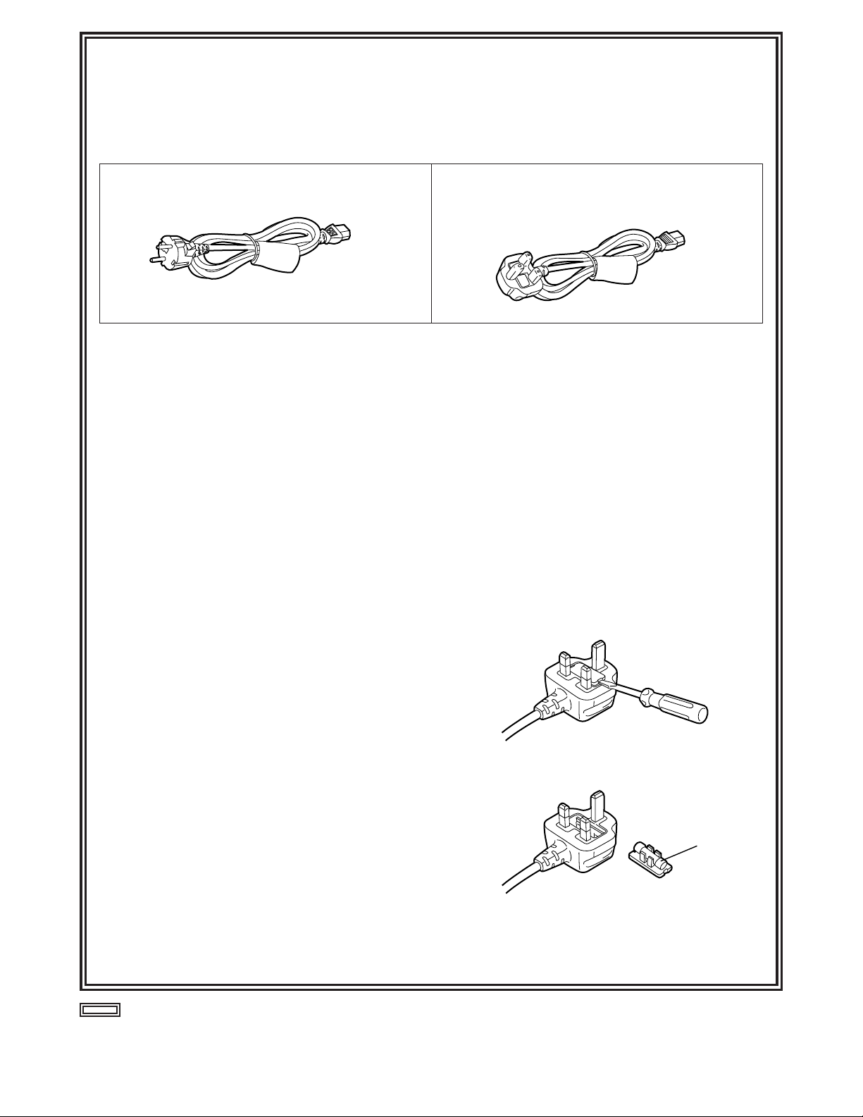
This product is equipped with 2 types of AC mains cable. One is for continental Europe, etc. and the other one is only
for U.K.
Appropriate mains cable must be used in each local area, since the other type of mains cable is not suitable.
FOR CONTINENTAL EUROPE, ETC.
Not to be used in the U.K.
FOR U.K. ONLY
If the plug supplied is not suitable for your socket
outlet, it should be cut off and appropriate one fitted.
How to replace the fuse
1.Open the fuse compartment with a screwdriver.
2.Replace the fuse.
Fuse
Page 3
2 (E)
ENGLISH
indicates safety information.
IMPORTANT
“Unauthorized recording of copyrighted
television programmes, video tapes and other
materials may infringe the right of copyright
owners and be contrary to copyright laws.”
$
Do not insert fingers or any objects into the video
cassette holder.
$
Avoid operating or leaving the unit near strong magnetic
fields. Be especially careful of large audio speakers.
$
Avoid operating or storing the unit in an excessively hot,
cold, or damp environment as this may result in
damage both to the recorder and to the tape.
$
Do not spray any cleaner or wax directly on the unit.
$
If the unit is not going to be used for a length of time,
protect it from dirt and dust.
$
Do not leave a cassette in the recorder when not in use.
$
Do not block the ventilation slots of the unit.
$
Use this unit horizontally and do not place anything on
the top panel.
$
Cassette tape can be used only for one-side, one
direction recording. Two-way or two-track recordings
cannot be made.
$
Cassette tape can be used for either Colour or Black &
White recording.
$
Do not attempt to disassemble the recorder.
There are no user serviceable parts inside.
$
If any liquid spills inside the recorder, have the recorder
examined for possible damage.
$
Refer any needed servicing to authorized service
personnel.
CAUTION:
Do not install or place this unit in a bookcase,
built-in cabinet or in another confined space
in order to keep well ventilated condition.
Ensure that curtains and any other materials
do not obstruct the ventilation condition to
prevent risk of electric shock or fire hazard
due to overheating.
WARNING:
TO REDUCE THE RISK OF FIRE OR SHOCK
HAZARD, DO NOT EXPOSE THIS EQUIPMENT
TO RAIN OR MOISTURE.
CAUTION:
TO REDUCE THE RISK OF FIRE OR SHOCK
HAZARD AND ANNOYING INTERFERENCE,
USE THE RECOMMENDED ACCESSORIES
ONLY.
Operating precaution
Operation near any appliance which generates
strong magnetic fields may give rise to noise in the
video and audio signals. If this should be the case,
deal with the situation by, for instance, moving the
source of the magnetic fields away from the unit
before operation.
$
DO NOT REMOVE PANEL COVER BY
UNSCREWING.
To reduce the risk of electric shock, do not remove
cover. No user serviceable parts inside.
Refer servicing to qualified service personnel.
$
THIS APPARATUS MUST BE EARTHED
To ensure safe operation the three-pin plug must be
inserted only into a standard three-pin power point
which is effectively earthed through the normal household wiring.
Extension cords used with the equipment must be
three-core and be correctly wired to provide
connection to earth. Wrongly wired extension cords
are a major cause of fatalities.
The fact that the equipment operates satisfactorily
does not imply that the power point is earthed and that
the installation is completely safe. For your safety, if in
any doubt about the effective earthing of the power
point, consult a qualified electrician.
O
This apparatus contains a lithium battery for memory back-up.
O
For the removal of the battery at the moment of the disposal at the end of the service life please
consult your dealer.
O
Do not throw away the battery. Instead, hand it in as hazardous waste.
O
Dit apparaat bevat een lithiumbatterij voor memory back-up.
O
Raadpleeg uw leverancier over de verwijdering van de batterij op het moment dat u het apparaat
bij einde levensduur afdankt.
O
Gooi de batterij niet weg, maar lever hem in als KCA.
Attention/Attentie
Page 4

3 (E)
Contents
Features . . . . . . . . . . . . . . . . . . . . . . . . . . .4
Parts and their functions . . . . . . . . . . . . .5
Front panel . . . . . . . . . . . . . . . . . . . . . . . . . . . . . .5
Rear panel . . . . . . . . . . . . . . . . . . . . . . . . . . . . . .10
Performing initial settings . . . . . . . . . . .11
Setting the date and time . . . . . . . . . . . . . . . . . . .11
Simple time adjustment . . . . . . . . . . . . . . . . . . . .12
Simple date and time adjustment . . . . . . . . . . . .13
Setting the recording time mode and number of
cameras . . . . . . . . . . . . . . . . . . . . . . . . . . . . . . . .14
Setting the recording mode . . . . . . . . . . . . . . . . .15
Frame recording and field recording . . .17
Connections . . . . . . . . . . . . . . . . . . . . . . .18
Recording . . . . . . . . . . . . . . . . . . . . . . . . .20
Playback . . . . . . . . . . . . . . . . . . . . . . . . . .21
Normal playback . . . . . . . . . . . . . . . . . . . . . . . . .21
Still-picture playback . . . . . . . . . . . . . . . . . . . . . .21
Changing over the screen display . . . . .22
Changing over the screen during playback . . . . .22
Changing between the 1-screen and 4-in-1 screen
display . . . . . . . . . . . . . . . . . . . . . . . . . . . . . . . . .22
Switching between the cameras . . . . . . . . . . . . .22
Useful functions . . . . . . . . . . . . . . . . . . .23
Memory stop . . . . . . . . . . . . . . . . . . . . . . . . . . . .23
Alarm recording and sensor (emergency)
recording . . . . . . . . . . . . . . . . . . . . . . . . . . . . . . .24
Alarm memory recall and power loss memory
recall . . . . . . . . . . . . . . . . . . . . . . . . . . . . . . . . . .26
Search playback (cue/review) . . . . . . . . . . . . . . .27
Alarm search (alarm recording section search) . .27
Time/date search . . . . . . . . . . . . . . . . . . . . . . . . .28
Internal timer recording . . . . . . . . . . . . . . . . . . . .29
External timer recording . . . . . . . . . . . . . . . . . . .33
Terminal connections . . . . . . . . . . . . . . .35
Alarm recording connections . . . . . . . . . . . . . . . .35
Tape-end output connections . . . . . . . . . . . . . . .36
Auto OFF output connections and recording output
connections . . . . . . . . . . . . . . . . . . . . . . . . . . . . .36
External timer input connections . . . . . . . . . . . . .36
Time setting connections . . . . . . . . . . . . . . . . . . .37
External timer input connections . . . . . . . . . . . . .37
Terminal signal levels . . . . . . . . . . . . . . .38
Setting menus . . . . . . . . . . . . . . . . . . . . .39
Setting method . . . . . . . . . . . . . . . . . . . . . . . . . .39
Menu page P1
TIME/DATE PRESET screen . . . . . . . . . . . . . . .40
REC LOCK screen . . . . . . . . . . . . . . . . . . . . . . .40
HOUR METER screen . . . . . . . . . . . . . . . . . . . . .40
Menu page P2
DISPLAY screen . . . . . . . . . . . . . . . . . . . . . . . . .41
REC LOSS INDICATOR screen . . . . . . . . . . . . .41
SUMMER TIME screen . . . . . . . . . . . . . . . . . . . .42
Menu page P3
RECORDING T-MODE & CAMERA screen . . . .43
Menu page P4
RECORDING MODE screen . . . . . . . . . . . . . . . .43
ALARM/SENSOR REC screen . . . . . . . . . . . . . .44
Menu page P5
VTR MODE SELECT screen . . . . . . . . . . . . . . . .45
Menu page P6
TAPE REMAIN screen . . . . . . . . . . . . . . . . . . . .46
REC REVIEW screen . . . . . . . . . . . . . . . . . . . . .46
ERROR WARN BUZZER screen . . . . . . . . . . . .47
REC WARNING screen . . . . . . . . . . . . . . . . . . . .47
Menu page P7
TERMINAL INPUT SELECT screen . . . . . . . . . .48
TERMINAL OUTPUT SELECT screen . . . . . . . .48
VIDEO OUT SEQUENCE screen . . . . . . . . . . . .49
EXT SWITCHER screen . . . . . . . . . . . . . . . . . . .49
Menu page P8
PROGRAM TIMER screen . . . . . . . . . . . . . . . . .50
INTERNAL WEEKLY TIMER screen . . . . . . . . . .50
Menu page P9
FREE SET TIMER screen . . . . . . . . . . . . . . . . . .51
Menu page P10
RS-232C PARAMETERS screen . . . . . . . . . . . .52
USER ID REC screen . . . . . . . . . . . . . . . . . . . . .52
Error messages . . . . . . . . . . . . . . . . . . . .53
Troubleshooting . . . . . . . . . . . . . . . . . . .54
Video head cleaning . . . . . . . . . . . . . . . .56
Condensation . . . . . . . . . . . . . . . . . . . . .56
Maintenance . . . . . . . . . . . . . . . . . . . . . . .56
Specifications . . . . . . . . . . . . . . . . . . . . .57
Page 5

4 (E)
ENGLISH
Features
Built-in frame switcher for supporting 16 cameras
O
The unit also supports asynchronous cameras.
O
The unit enables recording after the cameras are
switched over automatically as dictated by the
recording time mode.
O
During recording, the cameras can be switched and
their images viewed on a TV monitor at a time other
than the recording timing which has been set.
Digital recordings with a high picture quality
Digital recordings with a high picture quality can be
made on S-VHS tapes. The incorporation of highperformance A/D and D/A circuitry means that highquality digital recording is possible even when
recording after switching from one camera to another.
O
High picture quality mode: 520 lines for horizontal
resolution, 50 dB for S/N ratio
O
Standard picture quality mode: 380 lines for
horizontal resolution, 50 dB for S/N ratio
Wide selection of recording time modes
O
There is a choice of 14 different recording time
modes.
O
It is possible to switch between frame recording and
field recording.
Camera-specific playback
During playback, any camera can be selected and its
recording played back. During cue or review, as well,
any camera can be selected and its recording played
back.
Playback with 4 pictures simultaneously shown
on the screen
The pictures recorded by four of the cameras can be
selected and, by dividing the TV monitor screen into
four parts, all of the four pictures can be played back
at the same time on the respective parts of the
screen.
Date/time search function
The recording date and time (month / day / hours /
minutes) can be selected to initiate a search of the
recorded data.
Alarm search function
Recorded data that includes alarm recordings can be
searched.
3 hours, 9 hours, 12 hours, 18 hours, 24 hours, 48 hours, 72
hours, 96 hours, 120 hours, 180 hours, 240 hours, 360
hours, 480 hours and 960 hours
High reliability and high durability
O
IQ mechanism with top-notch reliability and
durability
O
Stable tape travel achieved using a 2DD reel motor
O
Automatic head cleaning function for cleaning the
head cylinder each time a tape is loaded
Space-saving design with 38 cm width and vertical
installation capability
The unit can be installed upright on its left-side panel
and secured using the special-purpose mounting
brackets (optional accessory STEN-B6730).
O
Do not install the unit upright on its right-side panel.
This may cause the unit to malfunction.
On-screen setting functions
The unit’s many and varied functions can be set on
the monitor screen.
Other features
O
75Ω termination ON/OFF function provided for
camera input (16) connectors
O
Switching between 8 camera input connectors and
8 camera loop-through outputs possible
O
RS-232C control facility
O
Audio recording (in the 3-hour to 24-hour time
modes)
O
Simple clock adjustment functions
O
Recording time and operating camera setting
function
O
Diverse internal timer and external timer functions
Page 6
5 (E)
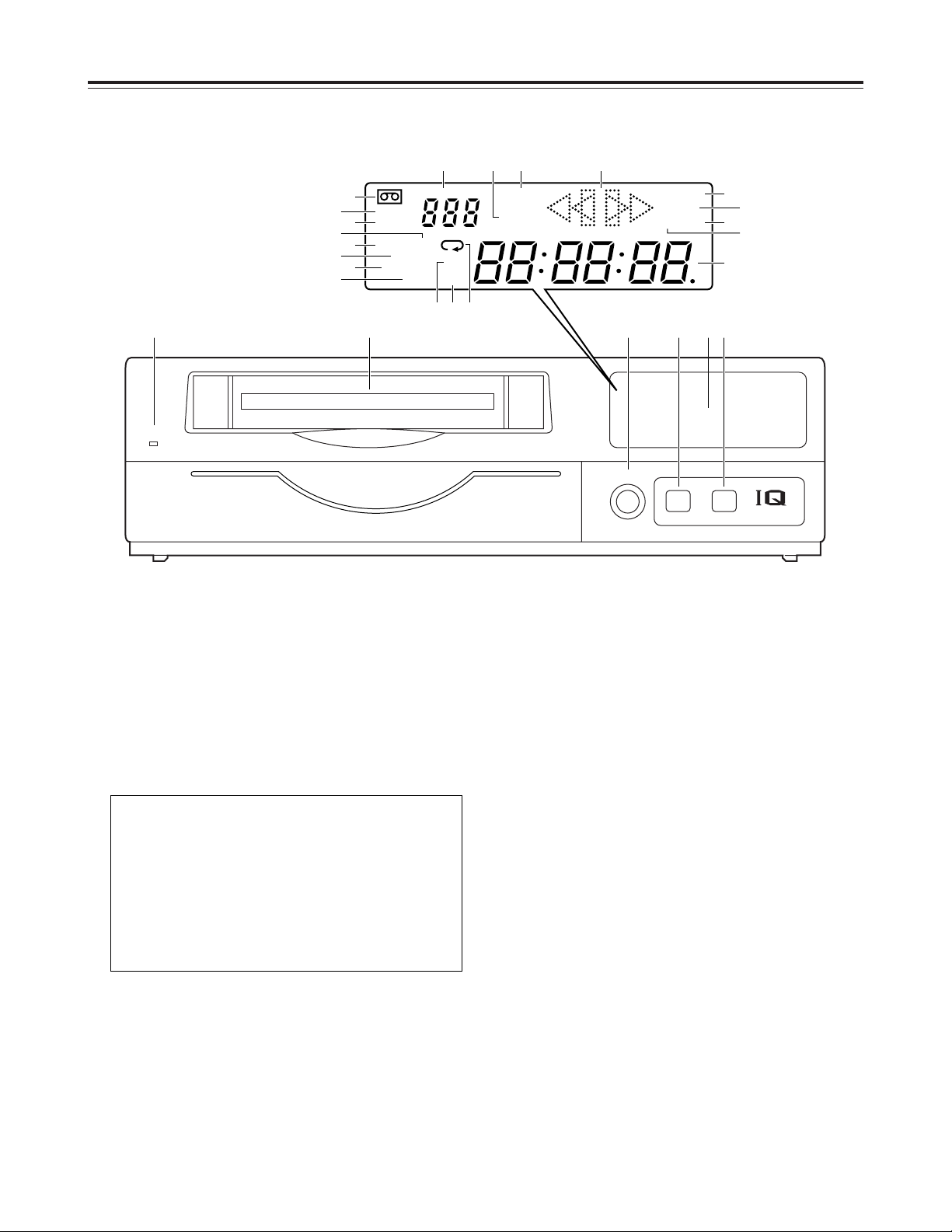
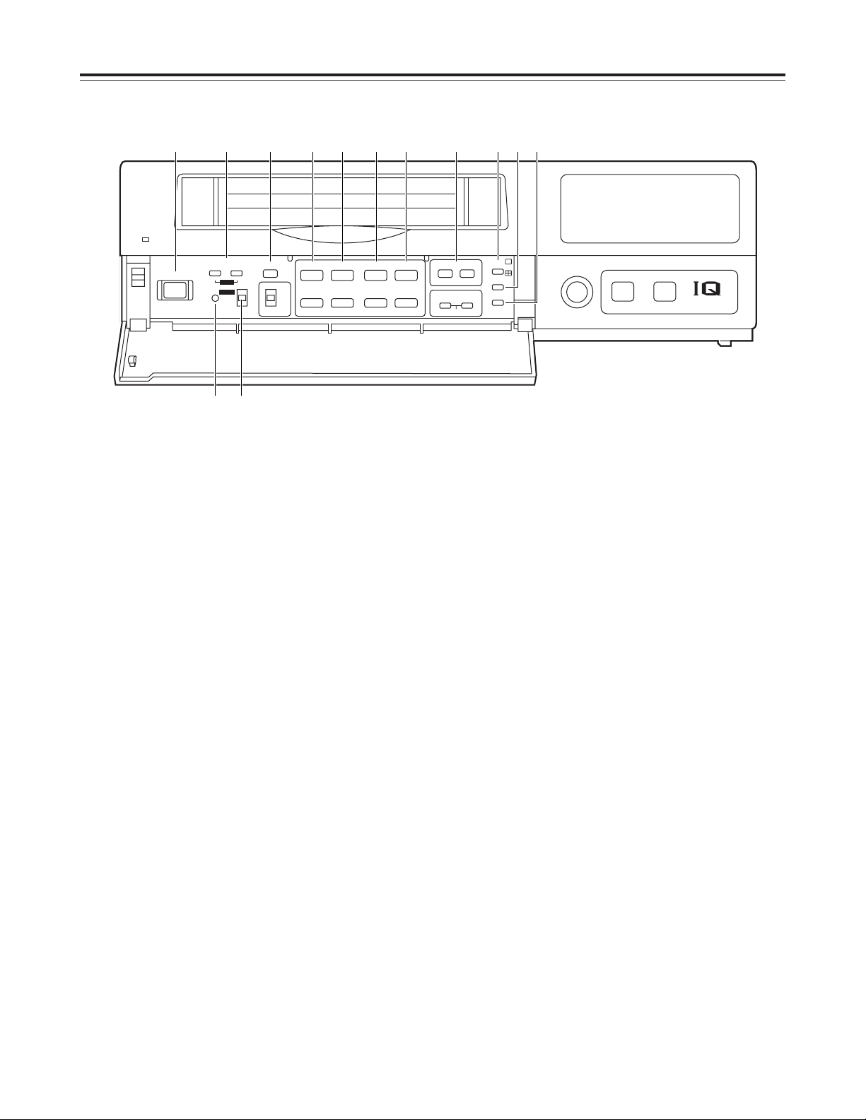
Parts and their functions
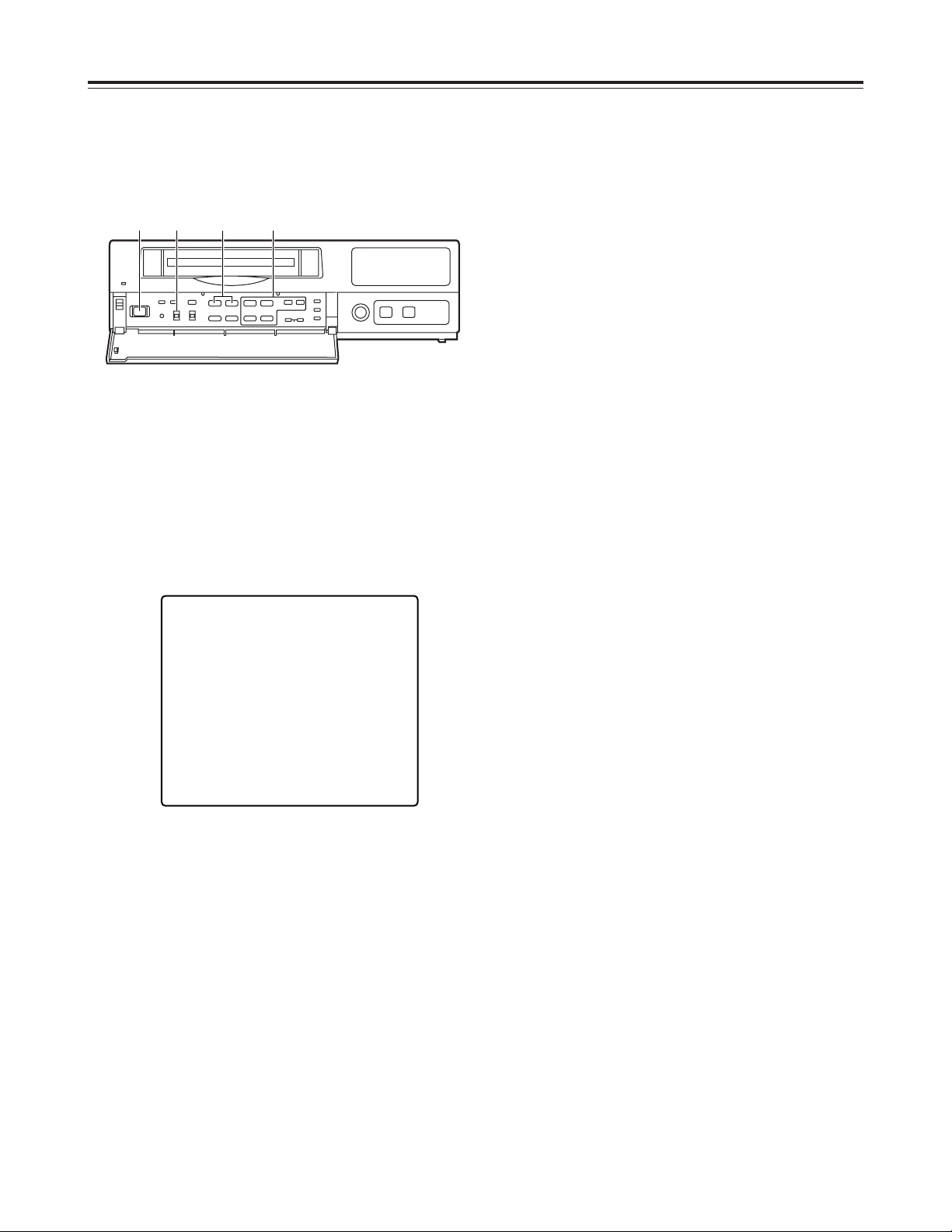
1
POWER lamp
This lights when the power is turned on.
2
Cassette insertion slot
Always use S-VHS cassette tapes. If a VHS tape is
inserted instead, it will be automatically ejected
when the REC button is pressed. A cassette tape
will also be ejected when the REC button is
pressed if its accidental erasure prevention tab has
been broken out.
3
EJECT button
Press this to eject the cassette tape.
It will not work unless it is pressed firmly.
Front panel
4
REC REVIEW button
Press this during recording to monitor what is being
recorded. Several images captured a moment
before the button was pressed are played back,
and then the recording mode is restored.
It takes about 10 seconds for the playback picture
to appear.
5
REC button
Press this to start recording.
6
EJECT
REC
REVIEW
MECHANISM
¥REC
<
POWER
USE S-VHS CASSETTE TAPE ONLY
#PUSH-OPEN
1 2 43 5
M
AS
ALARM
REC
y
m
SUM TIME
COUNT
CAMERA
PASS
HIGH
FRAME
d
TIME
MODE
H
REMAIN
LOCK
EXT INT
172
8
56
12
11
9
43
10
9 = ?>
<; :
1
2
6
8
5
3
4
7
@
D
C
A
B
This unit is designed to provide the high level of
reliability required of a time lapse recorder for use
in such applications as surveillance, security and
monitoring.
In order to ensure that this unit will perform
reliably in recording operations, it is
recommended that the following Panasonic video
tape be used:
S-VHS tape: SE-180 series (180-minute tape)
Page 7

6 (E)
ENGLISH
Parts and their functions
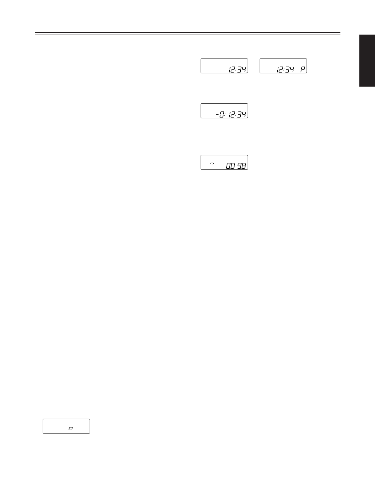
6
Display tube
1
=
Lights when a cassette tape is inserted.
It flashes when an error is detected as a result of
the recording review.
2
HIGH
Lights when a tape which was recorded in the
high picture quality mode is being played back
and when a tape is being recorded in the high
picture quality mode.
3
FRAME
Lights when a tape which was recorded in the
frame mode is being played back and when a
tape is being recorded in the frame mode.
4
SUM
Lights when the time is displayed in the summertime mode.
5
TIME
Lights when the time is displayed.
6
COUNT
Lights when the tape counter value is displayed.
7
CAMERA
Lights when the camera number is displayed.
8
PASS
Lights when the number of repeated tape
recordings (passes) is displayed.
9
TIME MODE
Indicates the recording time mode.
:
Lights when repeat recording has been set.
;
M
Lights when the memory stop mode has been
set.
<
AS (S)
AS : Lights when the alarm search mode has
been set.
S:Lights when the time search mode has
been set. The lamp flashes while a search
is in progress.
=
ALARM
Lights during an alarm recording.
Flashes upon completion of the alarm recording.
>
REC
Lights during recording or rec-pause.
?
Video operation mode displays
: Playback
: Reverse playback
REC : Recording, recording monitoring
REC : Rec-pause
: Still picture (flashes during frame
playback), frame feed
: Fast forward, cue
: Rewind, review
@
REMAIN
Flashes when the tape end is approaching (when
the remaining tape alarm mode has been set).
A
LOCK
Lights when the lock mode has been set by the
LOCK switch or using the REC LOCK item on
the setting menu.
B
EXT
Lights when the external timer mode has been
set.
C
INT
Lights when the internal timer mode has been
set.
D
Counter display
Displays the time or tape counter value; displays
the error code when an error has occurred.
In addition, when a discrepancy has arisen
between the number of cameras set and the
number of cameras actually connected because
one of the cables connected to the CAMERA IN
connectors has been disconnected or loosened,
the camera number concerned will flash on the
display to warn the user.
Page 8
7 (E)
Parts and their functions
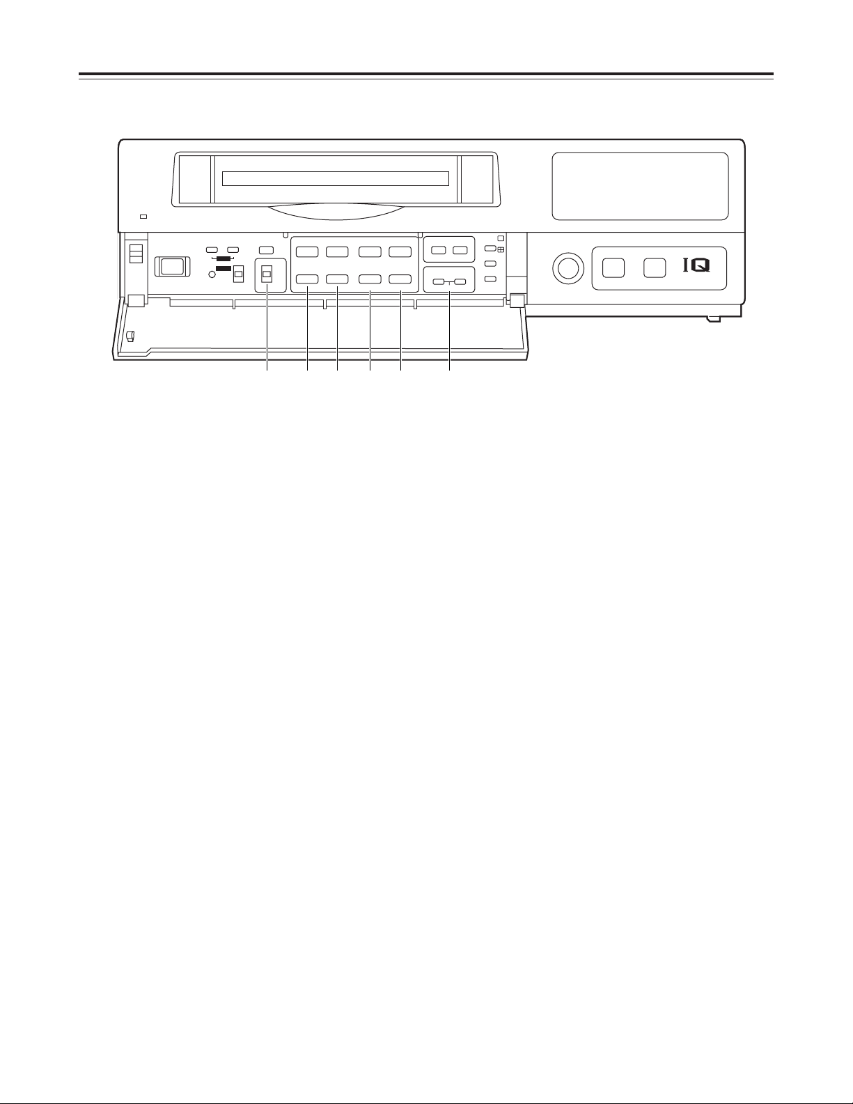
Front panel (sub panel)
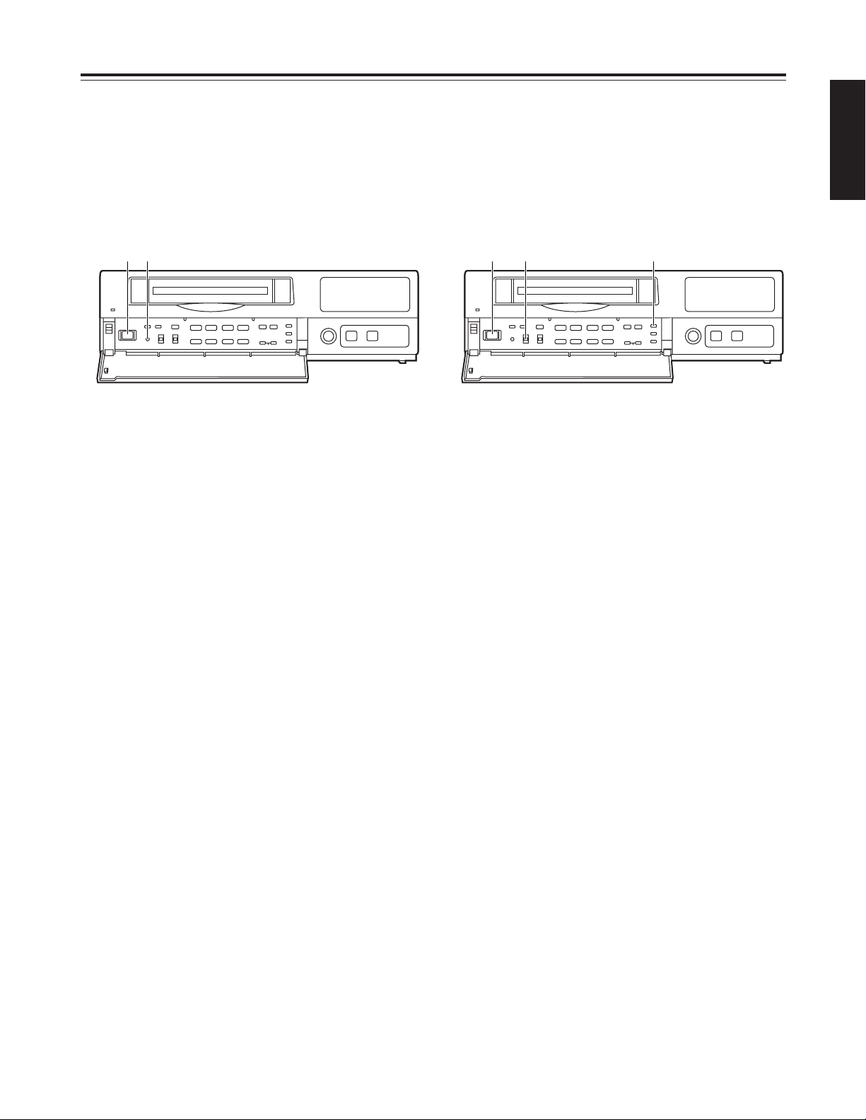
7
POWER switch
Used to turn the unit’s power ON and OFF.
When the power is turned on, the POWER lamp
lights, and the buzzer is sounded once.
8
TRACKING buttons
Press during normal playback to adjust the tracking.
When these buttons are pressed during still-picture
playback, the unit is set to the field still-picture or
frame still-picture mode.
However, the unit will not be set to the frame stillpicture mode if a tape recorded in the field mode
has been inserted.
9
TIMER MODE button
Used to select the timer mode. Each time it is
pressed, the mode is changed, and one of the
following mode lamps lights on the display tube.
No display: Normal recording
EXT : External timer recording
INT : Internal timer recording
:
REV PLAY button
Press to play back the tape in the reverse direction.
When the PROGRAM switch is at the MENU
position, this button functions as the PAGE (–)
button to select the setting menu screen.
When the PROGRAM switch is at the CLK POS
position, the button switches between the date
display and time display.
;
PLAY button
Press to play back the tape in the forward direction.
When the PROGRAM switch is at the MENU
position, this button functions as the PAGE (+)
button to select the setting menu screen.
When the PROGRAM switch is at the CLK POS
position, the button switches between the date
display and time display.
<
STOP button
Press to stop the operation mode.
When the PROGRAM switch is at the MENU
position, this button functions as the SHIFT (4)
button to select the items on the setting menu
screen.
When the PROGRAM switch is at the CLK POS
position, the button moves the screen display
position downward.
EJECT
REC
REVIEW
MECHANISM
¥REC
<
POWER
USE S-VHS CASSETTE TAPE ONLY
POWER
TRACKING
TIMER MODE
STILL
LOCK
REV PLAY PLAY STOP
SHIFT
SHIFTPAGE
PAUSE/STILL
TIME MODE
CAMERA
SEQUENCE
COUNTER
SEARCH
SET
REV ADV FWD ADV
REW
CB
FF
ALL
OFF
REC
MENU
OFF
:00
CLK
POS
FIELD FRAME
PROGRAM
21
21
65
∫;
34
34
3
4
34
H
H
ji
j i
j i
RESET
7 8 9 : ; < = > ? @ A
B C
Page 9
8 (E)
ENGLISH
Parts and their functions
=
PAUSE STILL button
Press to initiate rec-pause or still-picture playback.
When the unit remains in the pause or still-picture
playback mode for more than a prescribed period of
time, it is automatically set to the stop mode in
order to protect the tape.
When the PROGRAM switch is at the MENU
position, this button functions as the SHIFT (3)
button to select the items on the setting menu
screen.
When the PROGRAM switch is at the CLK POS
position, the button moves the screen display
position upward.
>
TIME MODE buttons
Press to select the recording time mode.
3H : 3-hour recording mode
9H : 9-hour recording mode
12H : 12-hour recording mode
18H : 18-hour recording mode
24H : 24-hour recording mode
48H : 48-hour recording mode
72H : 72-hour recording mode
96H : 96-hour recording mode
120H : 120-hour recording mode
180H : 180-hour recording mode
240H : 240-hour recording mode
360H : 360-hour recording mode
480H : 480-hour recording mode
960H : 960-hour recording mode
When the PROGRAM switch is at the MENU
position, these buttons function as the SET (+) and
(–) buttons to select the settings for the setting
menu items.
?
RESET button
Press while the counter value is shown on the
display tube by the COUNTER button to reset the
CTL counter.
When the camera number is shown on the display
tube by the COUNTER button during playback, this
button is used to switch the monitor screen
between 1-screen playback and 4-screen playback.
@
COUNTER button
Used to switch the display mode on the display
tube.
Each time the COUNTER button is pressed, the
mode is switched as follows.
Camera number display:
The current camera number is displayed.
CAMERA
172
8
56
12
11
9
43
10
Clock display:
The current time is displayed.
24-hour display 12-hour display
Counter display:
The tape counter is displayed.
Pass display:
This indicates the number of times (passes) repeat
recording has been performed when repeat
recording has been set.
A
SEARCH button
Press to select the search mode.
Each time this button is pressed in the counter
display mode, the search mode is switched, and
one of the following mode lamps lights on the
display tube:
M:Memory stop mode
AS : Alarm search mode
When the SEARCH button is pressed while the
time is displayed on the display tube by the
COUNTER button, the time search mode is set,
and “S” lights on the display tube.
B
:00 button
Press to set the seconds digits of the time to “00.”
The seconds are reset to “00” when this button is
pressed while the display shows 0 to 29 seconds,
and they are carried up to 1 minute and set to “00”
when it is pressed while the display shows 30 to 59
seconds.
C
PROGRAM switch
Used to display the menu and adjust the time.
Keep this switch at OFF for normal operation.
MENU:
The setting menu screen is displayed.
When the switch is set to the MENU position
while holding down the STOP button, the alarm
screen or power loss screen appears.
CLK POS:
Set the switch to this position when adjusting the
time or adjusting the screen display position.
PASS
COUNT
TIME
TIME
Page 10
9 (E)
Parts and their functions
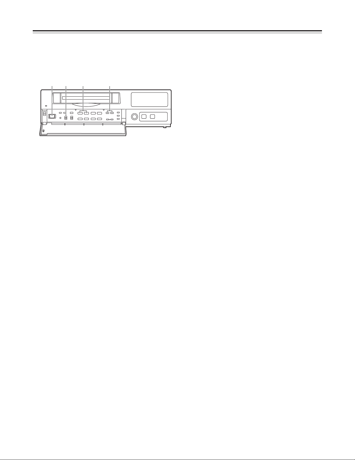
H
FWD ADV button
Press during still-picture playback to advance the
tape frame by frame in the forward direction.
When the PROGRAM switch is at the MENU
position, this button serves as the SHIFT (1)
button to select the setting menu screen items.
When the PROGRAM switch is at the CLK POS
position, the button moves the screen display
position toward the right.
I
CAMERA buttons
In the playback mode:
Press during playback to select the camera and
play back the pictures recorded by the selected
camera.
In any other mode:
When the buttons are pressed in any other
mode, the camera to be monitored can be
selected.
When the [4] button and [3] button are pressed
together, the auto sequence mode is
established.
When they are pressed in the auto sequence
mode, the unit is switched to the manual
sequence mode.
Front panel (sub panel)
D
LOCK switch
Used to set the lock mode.
ALL : All normal operations are suspended, and
LOCK lights on the display tube.
OFF : Normal operations can be conducted.
REC : Normal operations are suspended after
recording has commenced, and LOCK lights
on the display tube.
(REC REVIEW button operations are
acknowledged.)
E
REW/Cbutton
Press in the stop mode to rewind the tape.
When this button is pressed during playback or stillpicture playback, the tape is reviewed.
F B
/FF button
Press in the stop mode to fast forward the tape.
When this button is pressed during playback or stillpicture playback, the tape is cued.
G
REV ADV button
Press during still-picture playback to advance the
tape frame by frame in the reverse direction.
When the PROGRAM switch is at the MENU
position, this button serves as the SHIFT (2)
button to select the setting menu screen items.
When the PROGRAM switch is at the CLK POS
position, the button moves the screen display
position toward the left.
EJECT
REC
REVIEW
MECHANISM
¥REC
<
POWER
USE S-VHS CASSETTE TAPE ONLY
POWER
TRACKING
TIMER MODE
STILL
LOCK
REV PLAY PLAY STOP
SHIFT
SHIFTPAGE
PAUSE/STILL
TIME MODE
CAMERA
SEQUENCE
COUNTER
SEARCH
SET
REV ADV FWD ADV
REW
CB
FF
ALL
OFF
REC
MENU
OFF
:00
CLK
POS
FIELD FRAME
PROGRAM
21
21
65
∫;
34
34
3
4
34
H
H
ji
j i
j i
RESET
D E F G H I
Page 11
10 (E)
ENGLISH
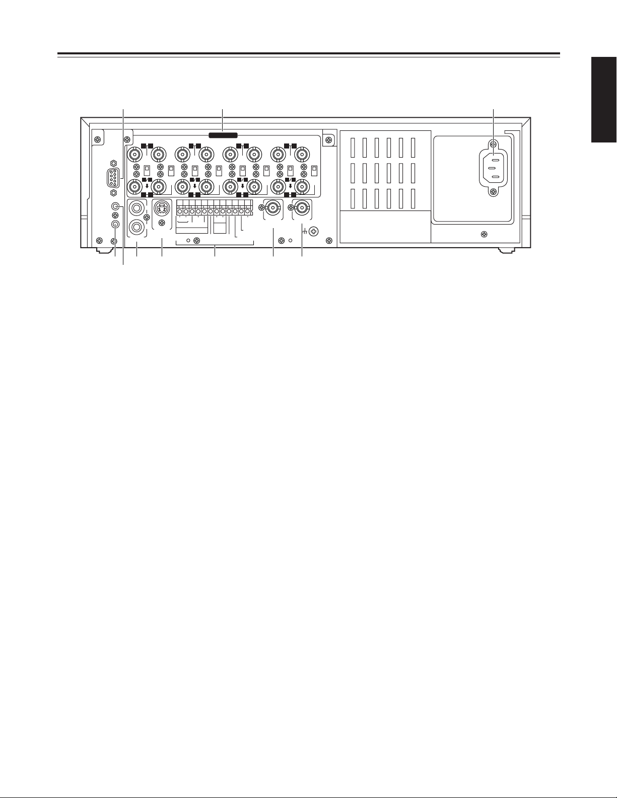
Parts and their functions
1
CAMERA IN connectors 1to qV(BNC),
75Ω termination/loop through selector switches
1
to 8, 75Ω termination switches 9to
qV
The camera and other external video input signals
(max. 16 inputs) are connected to these
connectors.
To use these connectors, select REC TYPE as the
RECORDING T-MODE & CAMERA setting on
menu screen P3.
<Note>
The 75Ω termination/loop through selector switches
1
to 8have 3 positions.
Switches 9to
qV
have 2 positions, 75 Ω termination
ON and OFF.
2
RS-232C connector
This is used to connect a personal computer or
other such device for controlling the unit.
3
MIC IN jack (M3)
This is used to connect the audio input signals from
the microphone. (600Ω impedance)
4
REMOTE connector
This is used to connect the model AG-A11 remote
controller available as an optional accessory.
5
AUDIO connectors (pin jacks)
These are the audio input and output connectors.
When a microphone has been connected to the
MIC IN jack, the sound from this jack takes
precedence in recording.
6
S-VIDEO OUT connector (4P)
This is used to connect the unit to a device
equipped with an S-video input connector.
7
Terminal section
8
EXT SW IN/VIDEO OUT connector (BNC)
The same video signals are output as the signals
from the VIDEO OUT connector 9. When EXT SW
IN is selected as the EXT SWITCHER MODE
setting on menu screen P7, the connector can be
made to serve as an input connector of the external
switcher.
9
VIDEO OUT connector (BNC)
The video signals from the camera switched by the
internal sequential switcher are output from this
connector during recording.
During playback, the playback pictures of the
recorded tape are output.
The menu screen or time adjustment screen is also
displayed.
:
AC IN socket
One end of the accessory power cord is connected
to this socket, and the other end is connected to a
household AC 220—240 V power outlet.
~AC IN
75
™
ON ON ON ON ON ON ON ON
75
™
CAMERA IN
75
™
75
™
OFF OFF OFF OFF
75
™
OFF
75
™
OFF
75
™
OFF
75
™
OFF
AUDIO
S-VIDEO
OUT
IN
OUT
1
2 GND
IN
REC IN GND
GND
TIME ADJ IN
TAPE END OUT
RESET
ALARM
EXT
TIMER
OUT
IN
OUT
WARNING
/REC OUT
EXT SW IN
/VIDEO OUT
VID
EO OU
T
RS232C
MIC IN
REMOTE
34
12 34 56
78
78
9
10
11
12 13 14 15 16
12 56
1 :
5 6 8 97
3
4
2
Rear panel
Page 12
11 (E)
Performing initial settings
1
Set the power switch to ON.
2
Set the PROGRAM switch to the MENU position.
The setting menu screen is shown on the TV
monitor.
4
Proceed as follows to set the date and time.
O
Use the (4) and (3) SHIFT buttons to move the
flashing part to the item whose setting is to be
changed.
O
Use the (2) and (1) SHIFT buttons to move the
flashing part to the column where the setting is
to be changed.
O
Press the (+) or (–) SET button to adjust the
figures.
3
Press the PAGE (+) or PAGE (–) button to display
the P1 TIME/DATE PRESET screen.
The flashing items are ones that can be set.
5
Upon completion of the settings, set the
PROGRAM switch to the OFF position.
The setting menu screen is cleared from the TV
monitor, and the normal mode is restored.
$
Setting the date and time
Before operating the unit, perform the following initial
settings.
<
21
21
65
∫;
34
34
34
H
H
1 2•5 3 4
P1
[TIME/DATE PRESET]
01- 1- 2000 SAT
0:00:00
[REC LOCK]
MODE OFF
[HOUR METER]
00000h
<Note>
The date and time settings are also updated when a
menu screen other than the P1 TIME/DATE PRESET
screen has been selected.
Page 13
12 (E)
ENGLISH
Performing initial settings
<
21
21
65
∫;
34
34
34
H
H
1 2
1
Set the power switch to ON.
2
The second digits of the time are reset to “00”
when the :00 button is pressed in synchronization
with the time signal, etc.
They are reset to “00” when the button is pressed
while the display shows 0 to 29 seconds. They are
carried up to 1 minute and set to “00” when it is
pressed while the display shows 30 to 59 seconds.
$
Simple time adjustment
If the clock is running fast or slow, follow the steps
below to adjust it.
When the clock is running up to 30 seconds fast or
slow
<
21
21
65
∫;
34
34
34
H
H
1 2•4 3
1
Set the power switch to ON.
3
The minute and second digits of the time are reset
to “00:00” when the RESET button is pressed in
synchronization with the time signal, etc.
They are reset to “00:00” when the button is
pressed while the display shows 0 to 14 minutes.
They are carried up to 1 hour and set to “00:00”
when it is pressed while the display shows 45 to 59
minutes.
When the clock is running up to 15 minutes fast or
slow
2
Set the PROGRAM switch to the “CLK POS”
position.
The counter display shows the current time, and
the “minutes” digits flash.
4
Upon completion of the settings, set the
PROGRAM switch to the OFF position.
Page 14
13 (E)
Performing initial settings
<
21
21
65
∫;
34
34
34
H
H
1 2•6 4 3•5
1
Set the power switch to ON.
2
Set the PROGRAM switch to the “CLK POS”
position.
The counter display shows the current time, and
the “minutes” digits flash.
3
Press the SET (+) or SET (–) button to set the
“minutes” digits.
4
Press the PAGE (+) or PAGE (–) button.
The current date appears, and the “date” digits
flash.
6
Upon completion of the settings, set the
PROGRAM switch to the OFF position.
5
Press the SET (+) or SET (–) button to set the
“date” digits.
$
Simple date and time adjustment
If the date and time are wrong, follow the steps below
to adjust them.
Page 15
14 (E)
ENGLISH
Performing initial settings
1
Set the power switch to ON.
2
Set the PROGRAM switch to the MENU position.
The setting menu screen is shown on the TV
monitor.
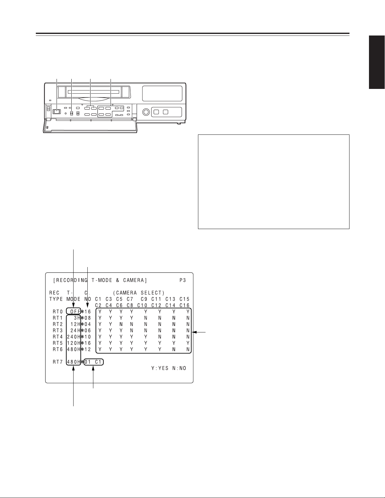
3
Press the PAGE (+) or PAGE (–) button to display
the P3 RECORDING T-MODE & CAMERA screen.
The flashing items are ones that can be set.
Fixed at 01 C1.
The cameras to be used are set here.
The cameras are set in pairs: C1-C2, C3-C4 and so on up to
C15-C16.
“Y” (YES) is set for each pair of cameras that is to be used.
A black burst signal (black screen) is recorded if no video
signals are supplied from a camera even when “Y” (YES)
has been set for that camera.
The number of cameras to be used is
displayed automatically here.
The recording time mode is set here.
Fixed at OFF.
$
Setting the recording time mode and
number of cameras
4
Follow the steps below to set the recording time
mode and number of cameras.
O
Use the (4), (3), (2) and (1) SHIFT buttons
to move the flashing part to the item whose
setting is to be changed.
O
Press the (+) and (–) SET buttons to change the
setting.
<
21
21
65
∫;
34
34
34
H
H
1 2•7 3•5 4•6
On the P3 RECORDING T-MODE & CAMERA
screen, set the number of cameras to be used and
their recording time modes for RT0 through RT7 in
the REC TYPE column ahead of time.
Different kinds of recordings can be undertaken by
setting these two items when normal recording or
timer recording is to be performed.
<Notes>
O
For RT0, T-MODE (recording time mode) is fixed
at OFF.
O
For RT7, the setting for the number of cameras to
be used is fixed at 1 unit for C1.
Page 16

15 (E)
Performing initial settings
7
Upon completion of the settings, set the
PROGRAM switch to the OFF position.
The setting menu screen is cleared from the TV
monitor, and the normal mode is restored.
$
Setting the recording mode
6
Set the recording mode by proceeding as follows.
O
Use the (4) and (3) SHIFT buttons to move the
flashing part to the item whose setting is to be
changed.
O
Press the (+) and (–) SET buttons to change the
setting.
5
Press the PAGE (+) or PAGE (–) button to display
the P4 RECORDING MODE screen.
The flashing items are ones that can be set.
P4 RECORDING MODE screen
O
Either field recording or frame recording is
selected for the FIELD/FRAME item setting.
O
Either high-quality recording or standard quality
recording is selected for the PICTURE QUALITY
item setting.
O
The recording time mode which was set on the P3
RECORDING T-MODE & CAMERA screen is
selected for the REC-TYPE setting.
When type RT0 is selected, the recording time
mode which was set using the TIME MODE
button on the front panel is used for recording.
When a type from RT1 to RT7 is selected, the
recording time mode which was set by RT1 to
RT7 is used for recording.
<Notes>
O
When RT7 is selected for the REC-TYPE item
setting, frame recording will be forcibly performed
regardless of the FIELD/FRAME item setting.
O
Recording is possible at 50 fields a second (which
is the same rate as for video machines used in the
home) if NORMAL is selected as the PICTURE
QUALITY item setting and the recording time
mode is set to 3H when RT7 has been selected
as the REC-TYPE item setting.
O
If the recording time mode is set to 3H when a
setting other than RT7 has been selected for the
REC-TYPE item, recording will be performed
automatically in the high picture quality mode
regardless of the PICTURE QUALITY item
setting.
[RECORDING MODE] P4
FIELD/FRAME FIELD
PICTURE QUALITY HIGH
REC-TYPE RT0 ( OFF¢16)
[ALARM/SENSOR REC]
MODE OFF
FIELD/FRAME FIELD
PICTURE QUALITY HIGH
DURATION 0.5min
BUZZER OFF
REPEAT OFF
GROUP ALARM1 RT0 ( OFF¢16)
GROUP ALARM2 RT0 ( OFF¢16)
Page 17
16 (E)
ENGLISH
Performing initial settings
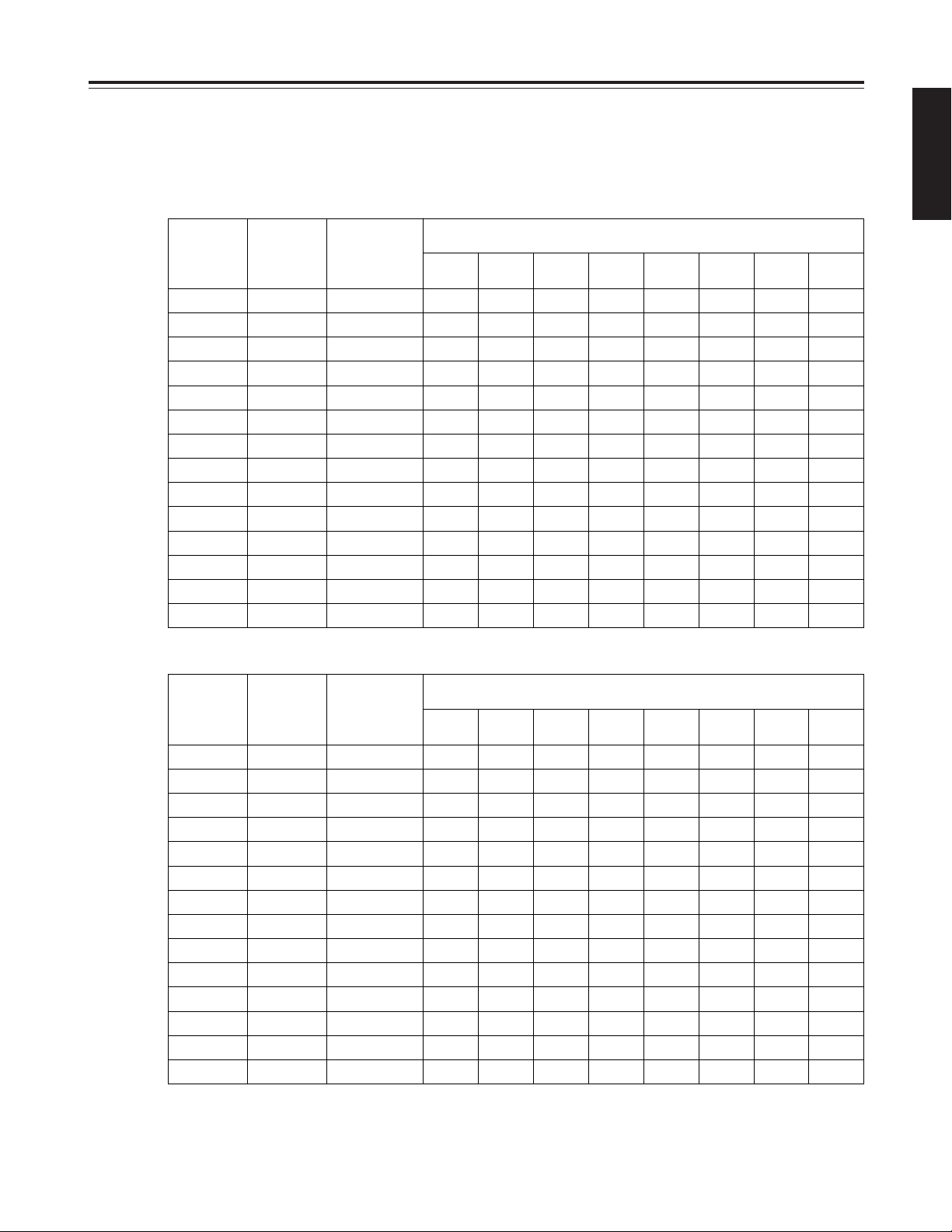
The table below shows the correlation between the recording time modes and number of cameras.
(When an S-VHS 180-minute tape is used)
Set the modes according to what is to be accomplished.
<Notes>
O
The actual recording time will be slightly longer than the figure indicated by the recording time mode.
O
In the frame recording mode, it takes twice as long for the cameras to be switched.
O
When the recording time mode is set to 3H, recording will be performed automatically in the high picture quality mode even
if the standard picture quality mode has been set.
High picture quality mode (field recording)
Recording
time mode
No. of fields
to be
recorded
per sec.
Time taken to
switch
cameras (sec.)
Time taken for recording turn to circulate and return to the first camera
for the no. of cameras connected
2
cameras4cameras6cameras8cameras10cameras12cameras14cameras16cameras
3H 25.00 0.040 0.08 0.16 0.24 0.32 0.40 0.48 0.56 0.64
9H 8.33 0.120 0.24 0.48 0.72 0.96 1.20 1.44 1.68 1.92
12H 5.00 0.200 0.40 0.80 1.20 1.60 2.00 2.40 2.80 3.20
18H 3.57 0.280 0.56 1.12 1.68 2.24 2.80 3.36 3.97 4.48
24H 2.78 0.360 0.72 1.44 2.16 2.88 3.60 4.32 5.04 5.76
48H 1.47 0.680 1.36 2.72 4.08 5.44 6.80 8.16 9.52 10.88
72H 1.00 1.000 2.00 4.00 6.00 8.00 10.00 12.00 14.00 16.00
96H 0.76 1.320 2.64 5.28 7.92 10.56 13.20 15.84 18.48 21.12
120H 0.61 1.640 3.28 6.56 9.84 13.12 16.40 19.68 22.96 26.24
180H 0.41 2.440 4.88 9.76 14.64 19.52 24.40 29.28 34.16 39.04
240H 0.31 3.240 6.48 12.96 19.44 25.92 32.40 38.88 45.36 51.84
360H 0.21 4.840 9.68 19.36 29.04 38.72 48.40 58.08 67.76 77.44
480H 0.16 6.440 12.88 25.76 38.64 51.52 64.40 77.28 90.16 103.04
960H 0.08 12.840 25.68 51.36 77.04 102.72 128.40 154.08 179.76 205.44
Standard picture quality mode (field recording)
Recording
time mode
No. of fields
to be
recorded
per sec.
Time taken to
switch
cameras (sec.)
Time taken for recording turn to circulate and return to the first camera
for the no. of cameras connected
2
cameras4cameras6cameras8cameras10cameras12cameras14cameras16cameras
3H 25.00 0.040 0.08 0.16 0.24 0.32 0.40 0.48 0.56 0.64
9H 16.67 0.060 0.12 0.24 0.36 0.48 0.60 0.72 0.84 0.96
12H 10.00 0.100 0.20 0.40 0.60 0.80 1.00 1.20 1.40 1.60
18H 7.14 0.140 0.28 0.56 0.84 1.12 1.40 1.68 1.96 2.24
24H 5.56 0.180 0.36 0.72 1.08 1.44 1.80 2.16 2.52 2.88
48H 2.94 0.340 0.68 1.36 2.04 2.72 3.40 4.08 4.76 5.44
72H 2.00 0.500 1.00 2.00 3.00 4.00 5.00 6.00 7.00 8.00
96H 1.52 0.660 1.32 2.64 3.96 5.28 6.60 7.92 9.24 10.56
120H 1.22 0.820 1.64 3.28 4.92 6.56 8.20 9.84 11.48 13.12
180H 0.82 1.220 2.44 4.88 7.32 9.76 12.20 14.64 17.08 19.52
240H 0.62 1.620 3.24 6.48 9.72 12.96 16.20 19.44 22.68 25.92
360H 0.41 2.420 4.84 9.68 14.52 19.36 24.20 29.04 33.88 38.72
480H 0.31 3.220 6.44 12.88 19.32 25.76 32.20 38.64 45.08 51.52
960H 0.16 6.420 12.84 25.68 38.52 51.36 64.20 77.04 89.88 102.72
Page 18
17 (E)
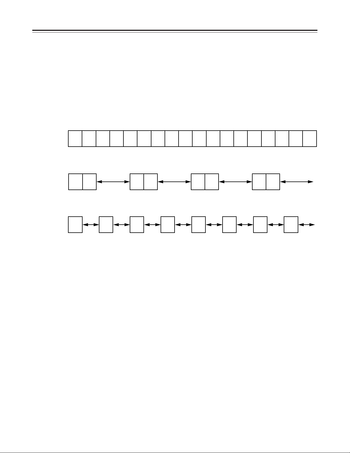
A B C D E F G H I J K L M N O P Q R
Actual image
REC REC
1
REC REC
1
REC REC
1
REC REC
1
Frame
recording
REC
1/2
REC
1/2
REC
1/2
REC
1/2
REC
1/2
REC
1/2
REC
1/2
REC
1/2
Field
recording
Camera
No.1
Camera
No.2
Camera
No.3
Camera
No.4
Camera
No.1
Camera
No.2
Camera
No.3
Camera
No.4
Camera
No.1
Camera
No.2
Camera
No.3
Camera
No.4
Frame recording and field recording
With frame recording, the image of one camera is
recorded in two fields, and after leaving a fixed
interval, the image of the next camera is recorded.
With field recording, the image of one camera is
recorded in one field, and after leaving half of the
interval for frame recording, the image of the next
camera is recorded.
The gaps between the recorded images are shorter
which enables the cameras to be switched in half the
time taken by frame recording.
Example where cameras 1 to 4 are connected
Page 19

18 (E)
ENGLISH
Connections
~AC IN
75
™
ON ON ON ON ON ON ON ON
75
™
CAMERA IN
75
™
75
™
OFF OFF OFF OFF
75
™
OFF
75
™
OFF
75
™
OFF
75
™
OFF
AUDIO
S-VIDEO
OUT
IN
OUT
1
2 GND
IN
REC IN GND
GND
TIME ADJ IN
TAPE END OUT
RESET
ALARM
EXT
TIMER
OUT
IN
OUT
WARNING
/REC OUT
EXT SW IN
/VIDEO OUT
VID
EO OU
T
RS232C
MIC IN
REMOTE
34
12 34 56
78
78
9
10
11
12 13 14 15 16
12 56
No. 1 No. 16
3
2
1
1
Set all 8 of the 75 Ω termination switches to the
ON position.
2
Connect the 16 cameras to CAMERA IN
connectors 1to qV.
3
Connect the TV monitor to the VIDEO OUT
connector.
Example of connections to switch between 16 cameras for recording
<Notes>
O
When connecting line-locked cameras, select ON
for the LL CAMERA item setting on the setting
menu shown on the P7 VIDEO OUT SEQUENCE
screen.
The images on the monitor will shake fractionally:
this is normal and not indicative of malfunctioning.
O
This unit does not contain a compensation circuit.
Install a compensator when the total length of the
cables (coaxial 3C-2V) used to connect the
cameras exceeds 200 meters.
There is no need to install a compensator if the total
length is under 400 meters if coaxial cables (5C-2V)
with minimal transmission loss are used.
This unit does not have an AGC (auto gain control) function for
video signal level adjustment.
Therefore, take due care with the 75 Ω termination for the
peripheral equipment.
Page 20

19 (E)
Connections
~AC IN
75
™
ON ON ON ON ON ON ON ON
75
™
CAMERA IN
75
™
75
™
OFF OFF OFF OFF
75
™
OFF
75
™
OFF
75
™
OFF
75
™
OFF
AUDIO
S-VIDEO
OUT
IN
OUT
1
2 GND
IN
REC IN GND
GND
TIME ADJ IN
TAPE END OUT
RESET
ALARM
EXT
TIMER
OUT
IN
OUT
WARNING
/REC OUT
EXT SW IN
/VIDEO OUT
VID
EO OU
T
RS232C
MIC IN
REMOTE
34
12 34 56
78
78
9
10
11
12 13 14 15 16
12 56
5
34
1
2
No. 1 No. 16
2
Set all 8 of the unit’s 75 Ω termination switches to
the ON position.
1
Connect the 16 cameras to the CAMERA IN
connectors of the frame switcher, and set the
frame switcher to the multi-screen display (4-in-1,
9-in-1 or 16-in-1 screens, etc.).
3
Connect the 16 camera outputs of the frame
switcher to CAMERA IN connectors 1through
qV
on the unit.
4
Connect the video output of the frame switcher to
the EXT SW IN/VIDEO OUT connector on the unit.
5
Connect the TV monitor to the VIDEO OUT
connector on the unit.
6
Select EXT SW IN as the MODE item setting on
the setting menu shown on the P7 EXT
SWITCHER screen.
The multiple images set by the frame switcher can
be viewed on the TV monitor in all modes except
for the playback mode.
When using a frame switcher during recording to output more than one screen image on the TV monitor
Page 21

20 (E)
ENGLISH
<
21
21
65
∫;
34
34
34
H
H
1 43
2
Recording
1
Set the power switch to ON.
When the power is turned on, the POWER lamp
lights, and the buzzer is sounded once.
2
Insert the cassette tape.
Press the EJECT button to eject the cassette tape.
It will not work unless it is pressed firmly.
<Note>
Always use S-VHS cassette tapes. If a VHS tape
is inserted instead, it will be automatically ejected
when the REC button is pressed.
A cassette tape will also be ejected when the REC
button is pressed if its accidental erasure
prevention tab has been broken out.
4
Press the REC button.
Recording is started in the set time mode using the
set cameras which are switched in turn
automatically.
To stop the recording, press the STOP button.
Proceed with recording after having performed the
connections and followed the steps for “Setting the
date and time” (page 11) and “Setting the recording
time mode and number of cameras” (page 14).
EJECT button
STOP button
3
Press the TIME MODE buttons to set the recording
time mode.
When 8 cameras are to be used, select “N” (NO) for
C9—C16 in the RT0 camera setting columns
(CAMERA SELECT) on the setting menu shown on
the P3 RECORDING T-MODE & CAMERA screen.
[RECORDING T-MODE & CAMERA] P3
REC T- C. (CAMERA SELECT)
TYPE MODE NO C1 C3 C5 C7 C9 C11 C13 C15
C2 C4 C6 C8 C10 C12 C14 C16
RT0 OFF¢8 Y Y Y Y N N N N
RT1 OFF¢16 Y Y Y Y Y Y Y Y
RT2 OFF¢16 Y Y Y Y Y Y Y Y
RT3 OFF¢16 Y Y Y Y Y Y Y Y
RT4 OFF¢16 Y Y Y Y Y Y Y Y
RT5 OFF¢16 Y Y Y Y Y Y Y Y
RT6 OFF¢16 Y Y Y Y Y Y Y Y
RT7 OFF¢01 C1
Y:YES N:NO
This unit is designed to provide the high level of
reliability required of a time lapse recorder for use
in such applications as surveillance, security and
monitoring.
In order to ensure that this unit will perform
reliably in recording operations, it is
recommended that the following Panasonic video
tape be used:
S-VHS tape: SE-180 series (180-minute tape)
When recording always in the same recording time
mode instead of setting the mode using the TIME
MODE button, set RT1 through RT7 for the REC
TYPE item on the setting menu shown on the P3
RECORDING T-MODE & CAMERA screen, and set
the REC TYPE (RT1 through RT7) to be used for
recording for the REC-TYPE item on the P4
RECORDING MODE screen.
Select RT7 when using one camera for the
recording. This enables the images of the camera
connected to the camera input 1connector to be
recorded.
Page 22

21 (E)
Playback
Still-picture playback
Normal playback
1
Set the power switch to ON, and insert the
cassette tape.
2
Press the PLAY button to start playback.
When 8 cameras are being used, the 8 camera
numbers appear on the camera number display of
the display tube, and the number of the camera
whose pictures are being played back is enclosed
in a square.
4
To stop the playback, press the STOP button.
<
21
21
65
∫;
34
34
34
H
H
2 41
3
1
Set the power switch to ON, and insert the
cassette tape.
2
Press the PLAY button to start playback.
3
Press the PAUSE STILL button.
The unit is now set to the still-picture playback
mode.
(When the frame advance button is pressed in the
still-picture playback mode, the tape is played back
one frame at a time.)
4
Press the PLAY button again to return to normal
playback.
5
To stop the playback, press the STOP button.
<
21
21
65
∫;
34
34
34
H
H
2•4531
CAMERA
172
8
5643
3
Press the CAMERA buttons to set the playback
camera.
<Note>
Press the (+) or (–) tracking button if block-shaped
video noise appears during playback in the 3-hour
mode. The tracking information will appear on the
display tube while the tracking button is held down.
Keep pressing the (+) or (–) tracking button until the
number of the tracking information reaches its
maximum.
Tracking information display
<Note>
If a switch is made to cameras No.13 to 16 when a
tape which was frame-recorded using cameras No.13
to 16 is being played back in the still-picture playback
mode, blue background signals will be output.
COUNT
Number at maximum
Page 23

22 (E)
ENGLISH
<
21
21
65
∫;
34
34
34
H
H
Changing over the screen display
1
During playback, one screen is displayed on the
TV monitor.
3
Press the RESET button to change over to the 4in-1 screen display.
Each time the RESET button is now pressed, the
display is switched between the 1-screen and 4-in1 screen.
Changing between the 1-screen and 4-in-1
screen display
Changing over the screen during
playback
1
1
Press the SEARCH button to move to the screen
with the white border.
2
43
1
C01 C02
C03 C04
2
Press the CAMERA button to set the camera.
3
Repeat steps 1 and 2 for the other screens to set
the camera for each.
1
2
43
1
C01 C02
C03 C04
CAMERA
172
8
56
12
11
9
43
10
The pictures recorded by a specific camera can be
monitored by pressing the CAMERA button during
playback.
When monitoring the pictures recorded by specific
cameras on the four screens in the 4-in-1 screen
display mode
Switching between the cameras
In the 1-screen display mode
In the 4-in-1 screen display mode
2
2
63
1
C01 C02
C03 C06
Four camera numbers are enclosed in squares on the
camera number display of the display tube, and the
square corresponding to the number of the selected
camera flashes. In addition, the numbers of the
cameras (C01/C02/C03/C04) appear in the centre of
the TV monitor.
CAMERA
172
8
56
12
11
9
43
10
CAMERA
172
8
56
12
11
9
43
10
CAMERA
172
8
56
12
11
9
43
10
2
Press the COUNTER button to establish the
camera number display mode.
SEARCH button
RESET button
CAMERA button
COUNTER button
<Note>
It is not possible to switch to the 4-in-1 screen display
when a tape which was frame-recorded using
cameras No.13 to 16 is to be played back.
Page 24

23 (E)
<
21
21
65
∫;
34
34
34
H
H
214
3
M
COUNT
Useful functions
Memory stop
2
Press the COUNTER button to establish the
counter display mode.
1
Press the STOP button to set the unit to the stop
mode.
3
Press the SEARCH button.
Check that “M” lights on the display tube and that
the memory stop mode is established.
Press the SEARCH button again if “AS” has lit.
4
Press the REW button if the counter reading is
higher than “0:00:00”; conversely, press the FF
button if it is lower (a negative value) than
“0:00:00.”
5
The counter reading approaches “0:00:00,” and the
tape is automatically set to the stop mode.
This function serves to rewind or fast forward the tape
to the “0:00:00” counter position and then
automatically set the unit to the stop mode when a
regular operation is being performed.
“M” lights.
Page 25

24 (E)
ENGLISH
Useful functions
Alarm recording and sensor
(emergency) recording
Alarm recording
This function enables recording with changes made to
the time mode and/or cameras used for recording
when an alarm signal (see page 35 for details on the
alarm recording connections) is input during
recording.
Sensor (emergency) recording
This function enables recording with changes made to
the time mode and/or cameras used for recording as
soon as an alarm signal is input even when the unit’s
power is off or in STOP mode.
1
Set the POWER switch to ON, and insert the
cassette tape.
2
Set the PROGRAM switch to the MENU position.
The setting menu screen now appears on the TV
monitor.
3
Press the PAGE (+) or PAGE (–) button to display
the P4 ALARM/SENSOR REC screen.
The flashing items are ones that can be set.
4
Take the following steps to set the recording mode
to be established when an alarm signal is input:
O
Use the (4) and (3) SHIFT buttons to move the
flashing part to the item whose setting is to be
changed.
O
Press the (+) and (–) SET buttons, and change
the setting.
<Notes>
O
Alarm recording and sensor recording are
selected using the MODE item.
Select OFF as the MODE item setting if
recording is not to be performed when an alarm
signal is input.
O
The recording time (DURATION) is set as
follows between 30 seconds and 10 minutes:
CONTINUE (up to the tape-end) or MANUAL
(while the alarm signal is input).
5
When the settings are completed, set the
PROGRAM switch to the OFF position.
The setting menu screen is cleared from the TV
monitor, and the normal mode is restored.
<
21
21
65
∫;
34
34
34
H
H
1 2•5 3 4
ALARM
[RECORDING MODE] P4
FIELD/FRAME FIELD
PICTURE QUALITY HIGH
REC-TYPE RT0 ( OFF¢16)
[ALARM/SENSOR REC]
MODE OFF
FIELD/FRAME FIELD
PICTURE QUALITY HIGH
DURATION 0.5min
BUZZER OFF
REPEAT OFF
GROUP ALARM1 RT0 ( OFF¢16)
GROUP ALARM2 RT0 ( OFF¢16)
Page 26

25 (E)
The power is off or
the tape is stopped
or in the internal
timer standby mode.
The power is off or
the tape is stopped
or in the internal
timer standby mode.
Sensor
recording
Alarm signal input
Recording
time
(DURATION)
Recording proceeds in the sensor
recording mode which has been set.
Useful functions
Sensor recording starts as soon as an alarm signal is
input even when the unit’s power is off or the tape has
stopped.
O
When OFF or ALARM is selected as the MODE
setting on the menu screen shown on P4
ALARM/SENSOR REC, the sensor recording
function does not work.
<Note>
When sensor recording is completed, the operation
prior to the alarm signal input is restored.
Press the REC button to start recording.
The alarm recording mode is established when an
alarm signal is input.
Once alarm recording is initiated, “ALARM” flashes on
the display tube.
When the STOP button is pressed, the display is
cleared, and recording stops.
O
When OFF or SENSOR is selected as the MODE
setting on the menu screen shown on P4
ALARM/SENSOR REC, the alarm recording
function does not work.
<Note>
When alarm recording is completed, the operation
prior to the alarm signal input is restored.
Recording Recording
Alarm
recording
Alarm signal input
Recording
time
(DURATION)
Recording proceeds in the alarm
recording mode which has been set.
When ALARM is selected as the MODE item
setting
When SENSOR is selected as the MODE item
setting
Both alarm recording and sensor recording are
performed.
If an alarm signal is input during recording, the alarm
recording mode is established, and when it is input
while the unit’s power is off or the tape has stopped,
sensor recording is started.
When ALARM/SENSOR is selected as the MODE
item setting
Page 27

26 (E)
ENGLISH
<
21
21
65
∫;
34
34
34
H
H
1 2
Useful functions
Alarm memory recall and power
loss memory recall
Alarm memory recall is a function for storing in the
memory those dates/times and number of occasions
on which the alarm recording and sensor recording
functions were activated.
Power loss memory recall is a function for storing in
the memory those dates/times and number of
occasions on which the primary power supply was
shut off due to a power outage, etc.
RESET button
<Notes>
O
Data for up to 8 alarms is stored on the ALARM
RECALL screen whereas data for up to 4 power
losses is stored on the POWER LOSS MEMORY
screen.
O
A total of 99 alarms and 99 power losses are stored
in the memory.
When 99 is exceeded, the count returns to “00.”
O
As with alarm recordings, the sensor recordings are
stored as alarm memory data.
O
The alarm memory data and power loss memory
data are stored in the memory circuit inside the unit.
They are not recorded on the tape.
O
When the PROGRAM switch is set to any position
except MENU, the ALARM RECALL screen and
POWER LOSS MEMORY screen displays are
cleared.
O
When the RESET button is pressed while the
ALARM RECALL screen is displayed, the memory
can be cleared, but the POWER LOSS MEMORY
screen is not cleared.
The following display appears when alarm recording
was never performed or when the primary power
supply was never shut off.
1
Set the POWER switch to ON.
2
Set the PROGRAM switch to the MENU position
while holding down the STOP button.
The ALARM RECALL screen and POWER LOSS
MEMORY screen now appear.
The alarm number/s and dates/times when the
alarm signal was input are displayed on the
ALARM RECALL screen.
The number of times the primary power source has
been shut off and the dates/times when this
happened are displayed on the POWER LOSS
MEMORY screen.
(Data is displayed in sequence with the latest at
the top of the screen.)
[ALARM RECALL]
¢¢ ¢¢–¢¢–¢¢¢¢ ¢¢:¢¢
¢¢ ¢¢–¢¢–¢¢¢¢ ¢¢:¢¢
¢¢ ¢¢–¢¢–¢¢¢¢ ¢¢:¢¢
¢¢ ¢¢–¢¢–¢¢¢¢ ¢¢:¢¢
¢¢ ¢¢–¢¢–¢¢¢¢ ¢¢:¢¢
¢¢ ¢¢–¢¢–¢¢¢¢ ¢¢:¢¢
¢¢ ¢¢–¢¢–¢¢¢¢ ¢¢:¢¢
¢¢ ¢¢–¢¢–¢¢¢¢ ¢¢:¢¢
[POWER LOSS MEMORY]
¢¢ ¢¢–¢¢–¢¢¢¢ ¢¢:¢¢
¢¢ ¢¢–¢¢–¢¢¢¢ ¢¢:¢¢
¢¢ ¢¢–¢¢–¢¢¢¢ ¢¢:¢¢
¢¢ ¢¢–¢¢–¢¢¢¢ ¢¢:¢¢
[ALARM RECALL]
¢¢ ¢¢–¢¢–¢¢¢¢ ¢¢:¢¢
¢¢ ¢¢–¢¢–¢¢¢¢ ¢¢:¢¢
¢¢ ¢¢–¢¢–¢¢¢¢ ¢¢:¢¢
¢¢ ¢¢–¢¢–¢¢¢¢ ¢¢:¢¢
¢¢ ¢¢–¢¢–¢¢¢¢ ¢¢:¢¢
¢¢ ¢¢–¢¢–¢¢¢¢ ¢¢:¢¢
¢¢ ¢¢–¢¢–¢¢¢¢ ¢¢:¢¢
¢¢ ¢¢–¢¢–¢¢¢¢ ¢¢:¢¢
[POWER LOSS MEMORY]
14 12 – 01 – 2000 12:00
13 10 – 05 – 2000 10:30
12 08 – 10 – 2000 9:20
11 3 – 02 – 2000 7:00
[ALARM RECALL]
29 12 – 30 – 2000 3:15
28 12 – 04 – 2000 12:10
27 10 – 25 – 2000 2:20
26 9 – 10 – 2000 2:30
25 8 – 11 – 2000 6:55
24 5 – 10 – 2000 3:22
23 4 – 11 – 2000 6:55
22 3 – 10 – 2000 3:22
[POWER LOSS MEMORY]
14 12 – 01 – 2000 12:00
13 10 – 05 – 2000 10:30
12 08 – 10 – 2000 9:20
11 3 – 02 – 2000 7:00
Page 28

27 (E)
Useful functions
Search playback (cue/review)
1
Set the POWER switch to ON, and insert the
cassette tape.
2
Press the PLAY button to start playback.
3
Press the FF button or REW button.
The unit performs search playback (cue or review)
while the FF button or REW button is held down.
Normal playback is restored when the FF button or
REW button is released.
<
21
21
65
∫;
34
34
34
H
H
21
3
<Notes>
O
To release the alarm search mode, press the
SEARCH button again to clear “AS” from the
display tube.
O
The alarm search function can be used to search
for only those alarm recording sections which were
recorded for more than 30 seconds in the 3-hour, 9hour, 12-hour, 18-hour or 24-hour recording time
mode.
O
When the FF button or REW button is pressed
during playback, search playback (cue or review) is
initiated, and even when the button is released,
search playback will continue if the unit is in the
alarm search mode.
2
Press the COUNTER button to establish the
counter display mode.
4
While the unit is in the stop, fast forward or rewind
mode, press the REW or FF button.
The first alarm recording section is searched in the
direction corresponding to the button pressed, and
the unit is set to the still-picture playback mode.
3
Press the SEARCH button.
Check that “AS” lights on the display tube and that
the alarm search mode is established.
Press the SEARCH button again if “M” has lit.
5
To play back the section, press the PLAY button.
Alarm search
(alarm recording section search)
1
Set the POWER switch to ON, and insert the
cassette tape containing the alarm recording.
<
21
21
65
∫;
34
34
34
H
H
251
4
3
AS
COUNT
“AS” lights.
<Notes>
O
When search playback is performed with a tape
which was frame-recorded using cameras No.13 to
16, the recorded images of all the cameras are
mixed and output even if a particular camera is
selected.
O
The picture will become quite blurred when search
playback is performed for a tape which was fieldrecorded in the standard picture quality mode. This
is normal and not indicative of malfunctioning.
Page 29

28 (E)
ENGLISH
<
21
21
65
∫;
34
34
34
H
H
51
3 2
S
TIME
4
Useful functions
3
Press the SEARCH button.
“S” lights on the display tube, and the TIME DATE
SEARCH screen appears on the TV monitor.
The time at which the recording was ended is
shown on the TIME DATE SEARCH screen.
When the tape is played back, the date and time
recorded on the tape are displayed.
When the RESET button is now pressed, the
display changes to the time at which the recording
was started.
2
Press the COUNTER button to establish the time
display mode.
Time/date search
This function is used to search for a particular
recording section by designating its date and time.
1
Set the POWER switch to ON, and insert the
cassette tape.
“S” lights.
4
Follow the steps below to set the search date and
time.
O
Use the (2) and (1) SHIFT buttons to move the
flashing part to the item whose setting is to be
changed.
O
Press the (+) and (–) SET buttons to set the
figure.
5
Press the PLAY button or REV PLAY button.
The recording section with the designated date and
time is now searched.
<Notes>
O
The tape comes to a stop at its end or start if no
recording section with the date and time was
found as a result of the search.
O
When the tape is stopped during recording, it
will stop at the border between the new
recording and old recording, and the continuity
in the date and time recorded on the tape will be
lost.
In this state, searches may not be performed
properly.
When the date or time to be searched is in the
newly recorded section, it is recommended that
the REV PLAY button be pressed. By pressing
this button, the tape is returned a little in the
reverse direction, the date and time data is
loaded, and the search is performed using this
data as a reference.
6
To release the time/date search mode, press any
of the function buttons.
[TIME DATE SEARCH]
25 – 12 10 : 25A
RESET : REC START TIME PRESET
PLAY : SEARCH START
RESET button
Page 30

29 (E)
Useful functions
Internal timer recording
Recording can be started and ended at the desired
times which are set using the internal timer.
<Note>
Before setting the internal timer recording, complete
the connections as well as the steps for “Setting the
date and time” (page 11) and “Setting the recording
time mode and number of cameras” (page 14).
Registering programmes for internal timer
recording
1
Set the POWER switch to ON, and insert the
cassette tape.
2
Set the PROGRAM switch to the MENU position.
The setting menu screen now appears on the TV
monitor.
3
Press the PAGE (+) or PAGE (–) button to display
the P8 PROGRAM TIMER screen.
The flashing items are ones that can be set.
4
Take the following steps to set the timer recording
mode.
O
Use the (4), (3), (2) and (1) SHIFT buttons
to move the flashing part to the item whose
setting is to be changed.
O
Press the (+) and (–) SET buttons, and change
the setting.
[PROGRAM TIMER] P8
(TIMER) START END REC-TYPE
PGM1 0:00 0:00 RT0 ( OFF¢16)
PGM2 0:00 0:00 RT0 ( OFF¢16)
PGM3 0:00 0:00 RT0 ( OFF¢16)
PGM4 0:00 0:00 RT0 ( OFF¢16)
PGM5 0:00 0:00 RT0 ( OFF¢16)
PGM6 0:00 0:00 RT0 ( OFF¢16)
PGM7 0:00 0:00 RT0 ( OFF¢16)
PGM8 0:00 0:00 RT0 ( OFF¢16)
[INTERNAL WEEKLY TIMER]
(SUN MON TUE WED THU FRI SAT DLY)
¢¢¢ ¢¢¢ ¢¢¢ ¢¢¢ ¢¢¢ ¢¢¢ ¢¢¢ ¢¢¢
¢¢¢ ¢¢¢ ¢¢¢ ¢¢¢ ¢¢¢ ¢¢¢ ¢¢¢ ¢¢¢
(TIMER)
Register the programmes (PGM1-PGM8) in this column when
using the internal timer to record them.
START
The recording start times are set in this column.
END
The recording end times are set in this column.
REC-TYPE
The recording type (RT0 to RT7) are set in this column.
<
21
21
65
∫;
34
34
34
H
H
1 2 3 4
Page 31

30 (E)
ENGLISH
<
21
21
65
∫;
34
34
34
H
H
INT
7
9
10 8
Useful functions
Weekly timer
This function is used to record for the programmed
duration every week at the same time on the same
day.
9
Upon completion of the settings, set the
PROGRAM switch to the OFF position.
The setting menu screen is cleared from the TV
monitor, and the normal mode is restored.
10
Press the TIMER MODE button on the front
panel and set it to the internal timer recording
mode (the “INT” lamp lights on the display tube).
<Notes>
O
If the cassette tape has not been inserted or
its accidental erasure prevention tab has
been broken out, the buzzer will sound, and
the INT lamp will flash.
At the same time, the cassette tape with its
accidental prevention tab been broken out will
be ejected. Furthermore, if a VHS tape has
been inserted, it will be automatically ejected.
O
To release the internal timer recording mode,
press the TIMER MODE button and turn off
the INT lamp on the display tube.
5
Use the (4), (3), (2) and (1) SHIFT buttons to
move the flashing part to the day-of-the-week
(SUN through SAT) item on the INTERNAL
WEEKLY TIMER screen.
6
Press the (+) and (–) SET buttons, and set the
programmes (PGM1-PGM8) registered on the
PROGRAM TIMER screen for the days of the
week concerned.
O
Two programmes each—one on the top line and
the other on the bottom—can be set for each
day of the week.
Leave “
¢¢¢
” unchanged where no
programmes are to be set.
O
When programmed time zone overlap on the
same day, the programme on the top line takes
precedence.
Daily timer
This function is used to record for the programmed
duration at the same time every day.
7
Use the (4), (3), (2) and (1) SHIFT buttons to
move the flashing part to the DLY item.
8
As with the weekly timer function, press the (+) and
(–) SET buttons, and set the programmes (PGM1PGM8) registered on the PROGRAM TIMER
screen.
<Note>
If the time zone programmed using the daily timer
overlaps the time zone programmed using the weekly
timer, the weekly timer will take precedence.
<
21
21
65
∫;
34
34
34
H
H
5 6
“INT” lamp
Page 32

31 (E)
Useful functions
5
Upon completion of the settings, set the
PROGRAM switch to the OFF position.
The setting menu screen is cleared from the TV
monitor, and the normal mode is restored.
6
Press the TIMER MODE button on the front panel
and set it to the internal timer recording mode (the
“INT” lamp lights on the display tube).
When the free-set timer is executed, “¢” will
appear on the right of the free-set timer number.
<Notes>
O
If the cassette tape has not been inserted or its
accidental erasure prevention tab has been
broken out, the buzzer will sound, and the INT
lamp will flash.
The buzzer will sound and the INT lamp will
flash also when the date/time or the programme
timer has not been set.
O
To release the internal timer recording mode,
press the TIMER MODE button to turn off the
INT lamp on the display tube.
Free-set timer
Recording is initiated for the programmed duration
on the date which has been set.
<Note>
If the time zone programmed using the free-set timer
overlaps the time zone programmed using the weekly
timer, the free-set timer takes precedence.
<
21
21
65
∫;
34
34
34
H
H
INT
4
2•5
6 3
“INT” lamp
[FREE SET TIMER] P9
MONTH DAY SET
1) ¢¢–
¢¢ ¢¢¢¢¢
2) ¢¢–
¢¢ ¢¢¢¢¢
3) ¢¢–
¢¢ ¢¢¢¢¢
4) ¢¢–
¢¢ ¢¢¢¢¢
5) ¢¢–
¢¢ ¢¢¢¢¢
6) ¢¢–
¢¢ ¢¢¢¢¢
7) ¢¢–
¢¢ ¢¢¢¢¢
8) ¢¢–
¢¢ ¢¢¢¢¢
9) ¢¢–
¢¢ ¢¢¢¢¢
10) ¢¢–
¢¢ ¢¢¢¢¢
11) ¢¢–
¢¢ ¢¢¢¢¢
12) ¢¢–
¢¢ ¢¢¢¢¢
1
Finish setting the weekly timer and daily timer.
2
Set the PROGRAM switch to the MENU position.
The setting menu screen now appears on the TV
monitor.
3
Press the PAGE (+) or PAGE (–) button to display
the P9 FREE SET TIMER screen.
The flashing items are ones that can be set.
MONTH
Set the month (1-12, ¢¢) of the date concerned in this
column.
Set “¢¢” if the month is not going to be registered.
“¢¢-¢¢-
¢¢¢¢¢
” appears for MONTH, DAY and SET.
DAY
Set the day (1-31) of the date concerned in this column.
SET
Select the programme which was set for the weekly timer.
SUN–SAT, P_OFF (POWER OFF mode throughout the day)
<Note>
Twelve days’ worth of dates can be set for the free-set timer.
[FREE SET TIMER] P9
MONTH DAY SET
1)
¢
5 – 3 SUN
1)
¢
5 – 4 SUN
1)
¢
5 – 5 SUN
4) ¢¢–
¢¢ ¢¢¢¢¢
5) ¢¢–
¢¢ ¢¢¢¢¢
6) ¢¢–
¢¢ ¢¢¢¢¢
7) ¢¢–
¢¢ ¢¢¢¢¢
8) ¢¢–
¢¢ ¢¢¢¢¢
9) ¢¢–
¢¢ ¢¢¢¢¢
10) ¢¢–
¢¢ ¢¢¢¢¢
11) ¢¢–
¢¢ ¢¢¢¢¢
12) ¢¢–
¢¢ ¢¢¢¢¢
4
Take the following steps to set the timer recording
mode.
O
Use the (4), (3), (2) and (1) SHIFT buttons
to move the flashing part to the item whose
setting is to be changed.
O
Press the (+) and (–) SET buttons, and change
the setting.
Page 33

32 (E)
ENGLISH
0:00
PGM1 (18H)
(24H) (18H)
PGM3 (9H)
DLY PGM8 (24H)
8:00 9:00 10:00 12:00 17:00 23:00 0:00
Useful functions
Example of some internal timer recording
programmes
$
Recording on Sunday
Sunday programmes
Actual recording operation
0:00
PGM2 (48H)PGM2 (48H)
(48H)(48H)
DLY PGM8 (24H)
8:00 9:00 10:00 12:00 17:00 23:00 0:00
$
Recording on Monday
Monday programmes
Actual recording operation
0:00
PGM5 (72H)PGM5 (72H)
(24H) (72H)(72H)
DLY PGM8 (24H)
8:00 9:00 10:00 12:00 17:00 23:00 0:00
6:00
$
Recording on Friday
Friday programmes
Actual recording operation
[PROGRAM TIMER] P8
(TIMER) START END REC-TYPE
PGM1 9:00 17:00 RT1 ( 18H¢04)
PGM2 9:00 9:00 RT3 ( 48H¢02)
PGM3 10:00 12:00 RT2 ( 9H¢06)
PGM4 0:00 0:00 RT0 ( OFF¢16)
PGM5 23:00 6:00 RT4 ( 72H¢04)
PGM6 10:00 11:00 RT0 ( OFF¢16)
PGM7 5:00 6:00 RT7 ( 120H¢01)
PGM8 8:00 12:00 RT6 ( 24H¢16)
[INTERNAL WEEKLY TIMER]
(SUN MON TUE WED THU FRI SAT DLY)
PGM1 PGM2
¢¢¢
PGM1 PGM6 PGM5
¢¢¢
PGM8
PGM3
¢¢¢ ¢¢¢ ¢¢¢ ¢¢¢ ¢¢¢
PGM7
¢¢¢
Page 34

33 (E)
Useful functions
External timer recording
Using an external timer, recording can be started and
ended at any time which has been set.
<Note>
Before setting the external timer recording, complete
the connections as well as the steps for “Setting the
date and time” (page 11) and “Setting the recording
time mode and number of cameras” (page 14).
When using an external timer connected to the
unit’s power cord (control exercised at the
primary power supply side)
1
Connect the external timer to the unit’s power cord,
and turn on its power.
2
Set the unit’s POWER switch to ON, and insert the
cassette tape.
3
Set the PROGRAM switch to the MENU position.
The setting menu screen now appears on the TV
monitor.
4
Press the PAGE (+) or PAGE (–) button to display
the P7 TERMINAL INPUT SELECT screen.
The flashing items are ones that can be set.
[TERMINAL INPUT SELECT] P7
EXT TIMER IN OFF
TIME ADJUST IN 9:00
[TERMINAL OUTPUT SELECT]
ALARM/SENSOR OUT CONTINUE
ERROR WARN/REC OUT WARNING
EXT TIMER OUT START 0:00
END 0:00
[VIDEO OUT SEQUENCE]
SW INTERVAL 2s
BYPASS CAMERA OFF
SW NOISE CANCEL ON
LL CAMERA OFF
[EXT SWITCHER]
MODE VIDEO OUT
5
Use the (4) and (3) SHIFT buttons to move the
flashing part to the EXT TIMER IN item, and press
the (+) and (–) SET buttons to select OFF as the
item’s setting.
6
Upon completion of the settings, set the
PROGRAM switch to the OFF position.
The setting menu screen is cleared from the TV
monitor, and the normal mode is restored.
7
Press the TIMER MODE button on the front panel
and set it to the external timer recording mode (the
“EXT” lamp lights on the display tube).
<Notes>
O
If the cassette tape has not been inserted or its
accidental erasure prevention tab has been
broken out, the buzzer will sound, and the EXT
lamp will flash.
At the same time, the cassette tape with its
accidental prevention tab been broken out will
be ejected. Furthermore, if a VHS tape has
been inserted, it will be automatically ejected.
O
To release the external timer recording mode,
press the TIMER MODE button to turn off the
EXT lamp on the display tube.
8
Set the external timer.
Recording will start automatically when the unit’s
power is turned on by the operation of the external
timer.
<Note>
While the unit’s power is not turned on in the external
timer recording mode, sensor recording will not be
performed even if an alarm signal is input.
<
21
21
65
∫;
34
34
34
H
H
EXT
3•6
72 4 5
“EXT” lamp
Page 35

34 (E)
ENGLISH
Useful functions
5
Use the (4) and (3) SHIFT buttons to move the
flashing part to the EXT TIMER IN item, and press
the (+) and (–) SET buttons to select ON as the
item’s setting.
6
Upon completion of the settings, set the
PROGRAM switch to the OFF position.
The setting menu screen is cleared from the TV
monitor, and the normal mode is restored.
7
Press the TIMER MODE button on the front panel
and set it to the external timer recording mode (the
“EXT” lamp lights on the display tube).
The power is automatically turned off, and the unit
waits for the control signal to be sent from the
external timer.
<Notes>
O
If the cassette tape has not been inserted or its
accidental erasure prevention tab has been
broken out, the buzzer will sound, and the EXT
lamp will flash.
O
To release the external timer recording mode,
press the TIMER MODE button to turn off the
EXT lamp on the display tube.
8
Set the external timer.
Recording will start automatically when the unit’s
power is turned on by the control signal sent from
the external timer.
When using an external timer connected to the
terminal section on the unit’s rear panel (control
exercised at the EXT TIMER connector)
1
Connect the external timer to the terminal section
on the unit’s rear panel, and turn on its power.
2
Set the unit’s POWER switch to ON, and insert the
cassette tape.
3
Set the PROGRAM switch to the MENU position.
The setting menu screen now appears on the TV
monitor.
4
Press the PAGE (+) or PAGE (–) button to display
the P7 TERMINAL INPUT SELECT screen.
The flashing items are ones that can be set.
[TERMINAL INPUT SELECT] P7
EXT TIMER IN OFF
TIME ADJUST IN 9:00
[TERMINAL OUTPUT SELECT]
ALARM/SENSOR OUT CONTINUE
ERROR WARN/REC OUT WARNING
EXT TIMER OUT START 0:00
END 0:00
[VIDEO OUT SEQUENCE]
SW INTERVAL 2s
BYPASS CAMERA OFF
SW NOISE CANCEL ON
LL CAMERA OFF
[EXT SWITCHER]
MODE VIDEO OUT
<
21
21
65
∫;
34
34
34
H
H
EXT
3•6
72 4 5
“EXT” lamp
Page 36

35 (E)
1
2 GND
IN
REC IN GND
TIME ADJ IN
TAPE END OUT
RESET
ALARM
EXT
TIMER
OUT
IN
OUT
WARNING
/REC OUT
+
–
Terminal connections
As shown below, firmly twist the end of the cord which
is to be connected to the terminal section.
External alarm lamp
External alarm buzzer
Alarm reset
switch
4V to 5V
Alarm switch 1
When an alarm signal is input to
ALARM IN 1, alarm recording or
sensor recording is performed.
Alarm switch 2
When an alarm signal is input to
ALARM IN 2, alarm recording or
sensor recording is performed.
External interface
Firmly twist or
solder here.
When connecting or disconnecting the
cord, press this part down using a
regular screwdriver.
Solid wire : 0.4 to 1.2 mm diameter
Twisted wire : 0.3 to 1.25 mm
(The diameter of the strands must be
0.18 mm or more.)
O
Failure to twist the end of the cord firmly can cause
short-circuiting.
Alarm recording connections
O
When alarm recording has been set for MODE on
the menu screen shown on P4 ALARM/SENSOR
REC, alarm recording is started when the alarm
switch is set to ON.
O
Alarm recording is released when the alarm reset
switch is set to ON.
Page 37

36 (E)
ENGLISH
1
2 GND
IN
REC IN GND
TIME ADJ IN
TAPE END OUT
RESET
ALARM
EXT
TIMER
OUT
IN
OUT
WARNING
/REC OUT
Terminal connections
Tape-end output connections
When the cassette tape comes to its end during
recording, the alarm device which has been installed
externally is triggered.
Alarm lamp
External
interface
1
2 GND
IN
REC IN GND
TIME ADJ IN
TAPE END OUT
RESET
ALARM
EXT
TIMER
OUT
IN
OUT
WARNING
/REC OUT
External timer input connections
An external timer can be used for recording.
O
Select ON for EXT TIMER IN on the menu screen
shown on P7 TERMINAL INPUT SELECT, and set
the front panel TIMER MODE button to EXT
(external timer recording).
The unit’s power is turned off, and recording is
started by the signal from the external timer.
External timer
1
2 GND
IN
REC IN GND
TIME ADJ IN
TAPE END OUT
RESET
ALARM
EXT
TIMER
OUT
IN
OUT
WARNING
/REC OUT
Auto OFF output connections and
recording output connections
The auto OFF output and recording output
connections are the same. Select between them
using ERROR WARN/REC OUT on the menu screen
shown on P7 TERMINAL OUTPUT SELECT.
Auto OFF output
When a problem has occurred in the unit, the alarm
device which has been installed externally is
triggered.
In this case, the error code appears on the display.
(See page 53.)
Recording output
When the unit is set to the recording mode, the alarm
device which has been installed externally is
triggered.
Alarm lamp
External
interface
Power OFF Power OFF
External timer signal
Recording proceeds in the recording
mode which was set by menu screen P4
RECORDING MODE.
External timer
recording
Page 38

37 (E)
1
2 GND
IN
REC IN GND
TIME ADJ IN
TAPE END OU
RESET
ALARM
EXT
TIMER
OUT
IN
OUT
WARNING
/REC OUT
Terminal connections
Time setting connections
When setting the unit’s time using an external
switch
O
Using the TIME ADJUST IN item on the menu
screen shown on P7 TERMINAL INPUT SELECT,
set the time which is to be set when the signal is
supplied from the external switch.
O
When the external switch is set to ON, the unit is
set to the set time.
Switch
1
2 GND
IN
REC IN GND
TIME ADJ IN
TAPE END OUT
RESET
ALARM
EXT
TIMER
OUT
IN
OUT
WARNING
/REC OUT
1
2 GND
IN
REC IN GND
TIME ADJ IN
TAPE END OUT
RESET
ALARM
EXT
TIMER
OUT
IN
OUT
WARNING
/REC OUT
External timer input connections
A second time lapse recorder unit can be used as an
external timer or the external switch for setting the
time.
O
Using the EXT TIMER OUT item on the menu
screen shown on P7 TERMINAL OUTPUT
SELECT, set the start time (START) and end time
(END) at which the control signals are to be output.
When using a second time lapse recorder as an external
timer
When using a second time lapse recorder as the external
switch for setting the time
1
2 GND
IN
REC IN GND
TIME ADJ IN
TAPE END OUT
RESET
ALARM
EXT
TIMER
OUT
IN
OUT
WARNING
/REC OUT
1
2 GND
IN
REC IN GND
TIME ADJ IN
TAPE END OUT
RESET
ALARM
EXT
TIMER
OUT
IN
OUT
WARNING
/REC OUT
Page 39

38 (E)
ENGLISH
External interface preparation
specifications
O
Use devices with ratings which support the actual
operating conditions.
Example of lamp lit by HIGH signal
(Lamp, etc.)
Power
Relay
Control signal
GND
Terminal signal levels
Terminal RemarksSignal level
ALARM IN
1/2
Ground input
V IH = 4.0 V to 5.0 V
V IL = 0.0 V to 0.6 V
T S100 ms
ALARM
RESET IN
High input
V IH = 4.0 V to 5.0 V
V IL = 0.0 V to 0.6 V
T S100 ms
T
V IH
V IL
T
V IH
V IL
REC IN Ground input
V IH = 4.0 V to 5.0 V
V IL = 0.0 V to 0.6 V
T S100 ms
T
V IH
V IL
EXT TIMER
IN
Ground input
Recording is
performed during
the V IL input (T).
V IH = 4.0 V to 5.0 V
V IL = 0.0 V to 0.6 V
T: Recording time
T
V IH
V IL
EXT TIMER
OUT
Ground output
Output time T is set
using the EXT
TIMER OUT item on
the menu screen
shown on P7
TERMINAL
OUTPUT SELECT.
V OL = 0.0 V to 0.6 V
V OL
T
OPEN OPEN
ALARM OUT Ground output
The output format is
set using the
ALARM/SENSOR
OUT item on the
menu screen shown
on P7 TERMINAL
OUTPUT SELECT.
V OH = 11.0 V to 13.0 V
V OL = 0.0 V to 0.6 V
4.7 kΩ pull-up resistor (+12V) output
V OH
V OL
Terminal RemarksSignal level
TIME ADJ IN Ground input
V IH = 4.0 V to 5.0 V
V IL = 0.0 V to 0.6 V
T S100 ms
T
V IH
V IL
TAPE END
OUT
Ground output
When REPEAT has
been selected as
the (TAPE END)
MODE setting on
the menu screen
shown on P5 (VTR
MODE SELECT),
output time T is 2
seconds. If a setting
other than REPEAT
is selected, the
signal will continue
to be output until
one of the function
buttons is pressed.
The signal will
continue to be
output until one of
the function buttons
is pressed also
when a setting other
than OFF has been
selected as the
LEVEL setting on
the menu screen
shown on P6 TAPE
REMAIN.
V OH = 11.0 V to 13.0 V
V OL = 0.0 V to 0.6 V
4.7 kΩ pull-up resistor (+12V) output
T
V OH
V OL
WARNING/R
EC OUT
Ground output
Open drain output
V OL = 0.0 V to 1.0 V
Max. 200 mA drive enabled
T
V OH
V OL
Page 40

39 (E)
Setting menus
Setting method
1
Set the POWER switch to ON.
2
Set the PROGRAM switch to the MENU position.
The setting menu screen now appears on the TV
monitor.
4
Use the (4), (3), (2) and (1) SHIFT buttons to
move the flashing part to the item whose setting is
to be changed.
3
Press the PAGE (+) or PAGE (–) button to display
the setting screen.
The flashing items are ones that can be set.
5
Press the (+) and (–) SET buttons to change the
setting.
6
Upon completion of the settings, set the
PROGRAM switch to the OFF position.
The setting menu screen is cleared from the TV
monitor, and the normal mode is restored.
<
21
21
65
∫;
34
34
34
H
H
POWER
TRACKING
TIMER MODE
STILL
LOCK
REV PLAY PLAY STOP
SHIFT
SHIFTPAGE
PAUSE/STILL
TIME MODE
CAMERA
SEQUENCE
COUNTER
SEARCH
SET
REV ADV FWD ADV
REW
CB
FF
ALL
OFF
REC
MENU
OFF
:00
CLK
POS
FIELD FRAME
PROGRAM
21
21
65
∫;
34
34
3
4
34
H
H
ji
j i
j i
RESET
1 2•6 53 4
Page 41

40 (E)
ENGLISH
Menu page P1
P1
[TIME/DATE PRESET]
01- 1- 2000 SAT
0:00:00
[REC LOCK]
MODE OFF
[HOUR METER]
00000h
Day: 01 to 31
Month: 1 to 12
Year: 2000 to 2099
Day of the week: SUN to SAT
Seconds: Fixed at 00
Minutes: 00 to 59
Hours: 0 to 23
Setting menus
TIME/DATE PRESET screen
Menu item Description of function
Year
Month
Day
Day of the week
Hours
Minutes
Seconds
For setting the date and time
01- 1-2000 SAT
0:00:00
REC LOCK screen
Menu item Description of function
MODE For setting the operation lock mode during recording.
ON : During recording, all the buttons and switches with the sole
exception of the REC REVIEW button are made nonoperational.
OFF
: Even during recording, all the buttons and switches can be
operated.
The underlining indicates the factory mode setting.
HOUR METER screen
Menu item Description of function
For displaying as a number of hours the cumulative recording
duration from the time when recording was started.
Page 42

41 (E)
Menu page P2
[DISPLAY] P2
CHARACTER WHITE
POSITION R-BOTTOM
TIME SELECT 24HOURS
DATE ON
TIME ON
T-MODE ON
REC/ALARM ON
[REC LOSS INDICATOR]
VIDEO OUT CAMERA
[SUMMER TIME]
MODE OFF
<WEEK> <MONTH> <TIME>
START LST-SUN 3 2:00
END LST-SUN 10 2:00
Setting menus
DISPLAY screen
Menu item Description of function
CHARACTER For setting the type of characters which are displayed on the monitor
screen.
WHITE
: White characters with black borders are displayed.
BLACK : Black characters with white borders are displayed.
POSITION For setting the position where the characters are displayed on the
monitor screen.
L-UPPER : The characters are displayed at the top left of the
screen.
R-UPPER : The characters are displayed at the top right of the
screen.
L-BOTTOM : The characters are displayed at the bottom left of the
screen.
R-BOTTOM : The characters are displayed at the bottom right of the
screen.
CENTRE : The characters are displayed in the centre of the
screen.
TIME SELECT For setting the 12-hour or 24-hour system for the time.
24HOURS : The 24-hour system is used to display the time.
AM/PM : The 12-hour AM/PM system is used to display the time.
DATE For setting whether to display the date on the monitor screen.
ON
: The date is displayed on the monitor screen.
OFF : The date is not displayed on the monitor screen.
TIME For setting whether to display the time on the monitor screen.
ON : The time is displayed on the monitor screen.
OFF : The time is not displayed on the monitor screen.
T-MODE For setting whether to display the recording time mode and camera
number on the monitor screen.
ON
: The recording time mode and camera number are displayed
on the monitor screen.
OFF : The recording time mode and camera number are not
displayed on the monitor screen.
REC/ALARM For setting whether to display the alarm number and operation mode
on the monitor screen.
ON : The alarm number and operation mode are displayed on the
monitor screen.
OFF : The alarm number and operation mode are not displayed on
the monitor screen.
The underlining indicates the factory mode setting.
REC LOSS INDICATOR screen
Menu item Description of function
VIDEO OUT For setting the video signals to be output to the monitor screen in all
modes except the recording mode.
CAMERA : Video signals from the camera are output to the monitor
screen.
BLUE : The blue background signals are output to the monitor
screen.
The underlining indicates the factory mode setting.
Page 43

42 (E)
ENGLISH
Menu page P2
[DISPLAY] P2
CHARACTER WHITE
POSITION R-BOTTOM
TIME SELECT 24HOURS
DATE ON
TIME ON
T-MODE ON
REC/ALARM ON
[REC LOSS INDICATOR]
VIDEO OUT CAMERA
[SUMMER TIME]
MODE OFF
<WEEK> <MONTH> <TIME>
START LST-SUN 3 2:00
END LST-SUN 10 2:00
Setting menus
SUMMER TIME screen
Menu item Description of function
MODE For switching the summer time setting ON or OFF.
ON : Summer time is set to ON.
OFF
: Summer time is set to OFF.
START For setting the day and time when summer time starts.
<WEEK>
For setting the week and day of the week when summer time is due
to start.
1ST : 1st week
2ND : 2nd week
3RD : 3rd week
4TH : 4th week
LST : Last week
SUN—SAT
Factory mode setting (LST-SUN)
<MONTH>
For setting the month at which summer time is due to start.
1—12
Factory mode setting (3)
<TIME>
For setting the time at which summer time is due to start.
The minutes cannot be set.
1:00—22:00
Factory mode setting (2:00)
END For setting the day and time when summer time ends.
<WEEK>
For setting the week and day of the week when summer time is due
to end.
1ST : 1st week
2ND : 2nd week
3RD : 3rd week
4TH : 4th week
LST : Last week
SUN—SAT
Factory mode setting (LST-SUN)
<MONTH>
For setting the month at which summer time is due to end.
1—12
Factory mode setting (10)
<TIME>
For setting the time at which summer time is due to end.
The minutes cannot be set.
1:00—22:00
Factory mode setting (2:00)
The underlining indicates the factory mode setting.
Page 44

43 (E)
Menu page P3
[RECORDING T-MODE & CAMERA] P3
REC T- C. (CAMERA SELECT)
TYPE MODE NO C1 C3 C5 C7 C9 C11 C13 C15
C2 C4 C6 C8 C10 C12 C14 C16
RT0 OFF¢16 Y Y Y Y Y Y Y Y
RT1 OFF¢16 Y Y Y Y Y Y Y Y
RT2 OFF¢16 Y Y Y Y Y Y Y Y
RT3 OFF¢16 Y Y Y Y Y Y Y Y
RT4 OFF¢16 Y Y Y Y Y Y Y Y
RT5 OFF¢16 Y Y Y Y Y Y Y Y
RT6 OFF¢16 Y Y Y Y Y Y Y Y
RT7 OFF¢01 C1
Y:YES N:NO
Menu page P4
[RECORDING MODE] P4
FIELD/FRAME FIELD
PICTURE QUALITY HIGH
REC-TYPE RT0 ( OFF¢16)
[ALARM/SENSOR REC]
MODE OFF
FIELD/FRAME FIELD
PICTURE QUALITY HIGH
DURATION 0.5min
BUZZER OFF
REPEAT OFF
GROUP ALARM1 RT0 ( OFF¢16)
GROUP ALARM2 RT0 ( OFF¢16)
Setting menus
RECORDING T-MODE & CAMERA screen
Menu item Description of function
REC TYPE The combination of recording time mode and number of cameras is
registered as the recording type.
RT0—RT7
<Notes>
O
The recording time mode (T-MODE) for RT0 is fixed at OFF.
O
The number of cameras (CAMERA SELECT) for RT7 is fixed at 1
(01).
T-MODE For setting the recording time mode.
OFF, 3H, 9H, 12H, 18H, 24H, 48H, 72H, 96H, 120H, 180H, 240H,
360H, 480H, 960H
<Note>
When OFF is selected as the recording time mode, the mode will
accord with the setting of the TIME MODE button (on the sub panel).
C. NO The number of cameras set for the CAMERA SELECT item appears
in this column.
CAMERA SELECT For selecting Y (yes) or N (no) to determine whether or not a
particular camera number is to be used.
Y : The camera will be used.
N : The camera will not be used.
<Note>
It is not possible to select N (NO) for all the cameras.
RECORDING MODE screen
Menu item Description of function
FIELD/FRAME For selecting field recording or frame recording.
FIELD
: Field recording is initiated.
FRAME: Frame recording is initiated.
PICTURE
QUALITY
For setting the quality of the pictures to be recorded.
HIGH : The pictures are recorded at a high quality.
NORMAL : The pictures are recorded at the standard quality.
REC-TYPE For selecting the recording type from what has been registered on
menu page P3.
RT0
—RT7
The underlining indicates the factory mode setting.
<Note>
When RT7 has been selected as the REC-TYPE item setting, the
FIELD/FRAME item setting is overridden and frame recording is forcibly
initiated.
Page 45

44 (E)
ENGLISH
Menu page P4
[RECORDING MODE] P4
FIELD/FRAME FIELD
PICTURE QUALITY HIGH
REC-TYPE RT0 ( OFF¢16)
[ALARM/SENSOR REC]
MODE OFF
FIELD/FRAME FIELD
PICTURE QUALITY HIGH
DURATION 0.5min
BUZZER OFF
REPEAT OFF
GROUP ALARM1 RT0 ( OFF¢16)
GROUP ALARM2 RT0 ( OFF¢16)
ALARM/SENSOR REC screen
Menu item Description of function
MODE For setting what recording operation is to be performed when an
alarm signal has been input.
OFF : The unit operates normally regardless of whether an
alarm signal is input.
ALARM/SENSOR:
Alarm recording or sensor recording is performed.
ALARM : Alarm recording is performed.
SENSOR : Sensor recording is performed.
FIELD/FRAME For selecting field recording or frame recording when alarm
recording or sensor recording is to be performed.
FIELD : Field recording is performed.
FRAME : Frame recording is performed.
PICTURE
QUALITY
For setting the picture quality when alarm recording or sensor
recording is to be performed.
HIGH : Recording is performed at a high quality.
NORMAL : Recording is performed at the standard quality.
NO CHANGE : Recording is performed at the current quality setting.
DURATION For setting the length of the alarm recording or sensor recording.
0.5min : Recording for 30 seconds.
1.0min : Recording for 1 minute.
1.5min : Recording for 1 minute and 30 seconds.
2.0min : Recording for 2 minutes.
3.0min : Recording for 3 minutes.
5.0min : Recording for 5 minutes.
10min : Recording for 10 minutes.
CONTINUE: Recording continues until the tape-end.
MANUAL : Recording is performed only while an alarm signal is
input.
BUZZER For setting whether the buzzer is to sound during alarm recording or
sensor recording.
ON : The buzzer sounds. It stops when any one of the function
buttons is pressed.
OFF : The buzzer does not sound.
GROUP ALARM1 For selecting the recording type from what was registered on menu
page P3 when alarm recording or sensor recording is to be
performed if an alarm signal is input to ALARM IN 1.
RT0—RT7
GROUP ALARM2 For selecting the recording type from what was registered on menu
page P3 when alarm recording or sensor recording is to be
performed if an alarm signal is input to ALARM IN 2.
RT0
—RT7
REPEAT For setting whether alarm recording or sensor recording is to be
performed if an alarm signal has been input while repeat recording is
underway or while the tape is being rewound.
OFF : Alarm recording or sensor recording is not performed when
the tape is being rewound.
If an alarm signal has been input even when tape rewinding is
completed, alarm recording or sensor recording is performed.
ON : Alarm recording or sensor recording (or both) is forcibly
performed even while the tape is being rewound.
The underlining indicates the factory mode setting.
Setting menus
<Note>
When RT7 has been selected as the REC-TYPE item setting, the
FIELD/FRAME item setting is overridden and frame recording is forcibly
initiated.
Page 46

45 (E)
Menu page P5
[VTR MODE SELECT] P5
(TAPE IN) STOP
(TAPE END)
MODE STOP
ALARM IN STOP
(EJECT OPERATION) EJECT
(VIDEO MODE) AUTO
(COMB FILTER) OFF
VTR MODE SELECT screen
Menu item Description of function
(TAPE IN) For setting the operation mode that is to be established when the
cassette tape has been inserted into the unit.
STOP : The unit is set to the stop mode.
REC : Recording is performed.
REW 5REC: The tape is first rewound to its start, and then
recording is performed.
(TAPE END)
MODE
For setting the operation mode that is to be established when the
tape-end position is reached.
STOP : The unit is set to the stop mode at the tape-end position.
BUZZER : The unit is set to the stop mode at the tape-end position,
and the buzzer sounds.
REW : The tape is rewound to its start position, and then the unit
is set to the stop mode.
REPEAT : The tape is rewound to its start position, and recording is
performed.
EJECT : The tape is ejected at the tape-end position.
(TAPE END)
ALARM IN
For setting the operation mode that is to be established when the
tape-end position is reached after alarm recording or sensor
recording has been performed.
STOP
: The unit is set to the stop mode at the tape-end
position.
The tape is ejected when EJECT has been selected as
the (TAPE END) MODE setting.
CONTINUE: The unit continues with the operation selected as the
(TAPE END) MODE setting regardless of whether an
alarm signal is input.
(EJECT
OPERATION)
For setting the EJECT button operation.
EJECT : The tape is ejected by operating the button.
REW 5EJECT: The tape is ejected after it has been rewound to its
start position by operating the button.
(VIDEO MODE) For setting the colour of the video output signal.
AUTO : The colour is automatically switched in accordance with the
input signal.
B/W : The signal is forcibly set to monochrome.
(COMB FILTER) For selecting the filter or filters to be used when separating the
composite signal into its Y (luminance) and C (chrominance)
components.
ON : The comb filter is used to separate the composite signal
into its Y (luminance) and C (chrominance) components.
OFF
: The notch filter is used to separate the Y (luminance)
component, and the band-pass filter is used to separate the
C (chrominance) component.
The underlining indicates the factory mode setting.
Setting menus
Page 47

46 (E)
ENGLISH
Menu page P6
[TAPE REMAIN] P6
LEVEL OFF
BUZZER OFF
[REC REVIEW]
AUTO OFF
ERROR BUZZER OFF
[ERROR WARN BUZZER]
MODE OFF
[REC WARNING]
REC LOSS BUZZER OFF
TAPE REMAIN screen
Menu item Description of function
LEVEL For setting at what point REMAIN is to flash on the display tube and
the remaining tape warning is to be displayed when the tape-end
position is about to be reached. (When using a 180-minute tape)
The REMAIN flashing is released when any button is pressed.
OFF : The remaining tape warning is not displayed.
2% : The warning is displayed when the remaining tape amount is
less than approximately 2%.
10% : The warning is displayed when the remaining tape amount is
less than approximately 10%.
20% : The warning is displayed when the remaining tape amount is
less than approximately 20%.
30% : The warning is displayed when the remaining tape amount is
less than approximately 30%.
BUZZER For setting whether the buzzer is to sound when the tape-end
position is about to be reached. The buzzer is stopped when any
button is pressed.
ON : The buzzer sounds at the position which was set for the
LEVEL item.
OFF
: The buzzer does not sound.
The underlining indicates the factory mode setting.
REC REVIEW screen
Menu item Description of function
AUTO For setting automatic REC REVIEW.
(This function plays back the recording after recording for a specific
time in order to detect whether the proper video level is being
maintained during recording.)
ON : REC REVIEW is performed automatically.
If the level detected is found to be unacceptable, the tape is
loaded and unloaded two times, and REC REVIEW is
automatically performed again. If it is still unacceptable even
after this, recording is performed.
OFF : REC REVIEW is not performed automatically.
ERROR BUZZER For setting whether the buzzer is to sound when it is discovered by
REC REVIEW that the proper video level was not maintained.
ON : The buzzer sounds. It is stopped when any button is pressed.
OFF
: The buzzer does not sound.
The underlining indicates the factory mode setting.
Setting menus
Page 48

47 (E)
Menu page P6
[TAPE REMAIN] P6
LEVEL OFF
BUZZER OFF
[REC REVIEW]
AUTO OFF
ERROR BUZZER OFF
[ERROR WARN BUZZER]
MODE OFF
[REC WARNING]
REC LOSS BUZZER OFF
ERROR WARN BUZZER screen
Menu item Description of function
MODE For setting whether the buzzer is to sound when a problem occurs in
the unit and the power is automatically turned off.
ON : The buzzer sounds.
OFF : The buzzer does not sound.
The underlining indicates the factory mode setting.
REC WARNING screen
Menu item Description of function
REC LOSS
BUZZER
For setting whether the buzzer is to sound when the unit is kept in
the stop mode for a prolonged period of time. The buzzer is stopped
when any button is pressed.
OFF : The buzzer does not sound.
5min : The buzzer sound when the unit is kept in the stop mode for
5 minutes.
10min: The buzzer sound when the unit is kept in the stop mode for
10 minutes.
20min: The buzzer sound when the unit is kept in the stop mode for
20 minutes.
30min: The buzzer sound when the unit is kept in the stop mode for
30 minutes.
<Note>
After the buzzer has been stopped by pressing any button, a mode
other than STOP is established and if the stop status should persist,
the buzzer will sound again in accordance with the menu item
setting.
The underlining indicates the factory mode setting.
Setting menus
Page 49

48 (E)
ENGLISH
Menu page P7
[TERMINAL INPUT SELECT] P7
EXT TIMER IN OFF
TIME ADJUST IN 9:00
[TERMINAL OUTPUT SELECT]
ALARM/SENSOR OUT CONTINUE
ERROR WARN/REC OUT WARNING
EXT TIMER OUT START 0:00
END 0:00
[VIDEO OUT SEQUENCE]
SW INTERVAL 2s
BYPASS CAMERA OFF
SW NOISE CANCEL ON
LL CAMERA OFF
[EXT SWITCHER]
MODE VIDEO OUT
TERMINAL INPUT SELECT screen
Menu item Description of function
EXT TIMER IN For setting whether the signals from the external timer connected to
the rear panel terminal section are to be acknowledged in the
external timer recording mode.
ON : The signals from the external timer are acknowledged.
OFF : The signals from the external timer are not acknowledged.
Select OFF when using an external timer which has been
connected to the unit’s power cord.
TIME ADJUST IN For setting the time to be set when signals have been input from the
component connected to TIME ADJ IN on the rear panel terminal
section.
00:00 to 23:59, RESET
Factory setting mode (9:00)
<Notes>
O
The seconds are fixed at “00.”
O
When signals are input after RESET has been set, the minutes of
the time are set to “00.”
The minute setting is returned to “00” while it is between 0 and 15
minutes when signals are input.
The hour is carried up and the minutes are set to “00” while the
setting is between 45 and 59 minutes when signals are input.
The underlining indicates the factory mode setting.
TERMINAL OUTPUT SELECT screen
Menu item Description of function
ALARM/SENSOR
OUT
For setting how the control signals are to be output to the component
connected to ALARM OUT on the rear panel terminal section when
alarm recording or sensor recording is performed.
CONTINUE : The control signals continue to be output even after
recording.
ALARM REC : The control signals are output only during alarm
recording or sensor recording.
ERROR WARN/
REC OUT
For setting how the control signals are to be output to the component
connected to WARNING/REC OUT on the rear panel terminal
section when a problem has occurred in the unit.
WARNING : The control signals continue to be output.
REC : The control signals are output only during recording.
EXT TIMER OUT For setting the START time and END time at which the control
signals are to be output to the component connected to EXT TIMER
OUT on the rear panel terminal section.
0:00
—23:59
<Note>
The control signals are not output when the same time has been set
for both the START and END times.
The underlining indicates the factory mode setting.
Setting menus
Page 50

49 (E)
Menu page P7
[TERMINAL INPUT SELECT] P7
EXT TIMER IN OFF
TIME ADJUST IN 9:00
[TERMINAL OUTPUT SELECT]
ALARM/SENSOR OUT CONTINUE
ERROR WARN/REC OUT WARNING
EXT TIMER OUT START 0:00
END 0:00
[VIDEO OUT SEQUENCE]
SW INTERVAL 2s
BYPASS CAMERA OFF
SW NOISE CANCEL ON
LL CAMERA OFF
[EXT SWITCHER]
MODE VIDEO OUT
VIDEO OUT SEQUENCE screen
Menu item Description of function
SW INTERVAL For setting the timing at which the video signals which are supplied
from the camera and which are to be output from the rear panel
VIDEO OUT connector are to be switched.
1s (1 sec.), 1.5s (1.5 sec.), 2s (2 sec.), 2.5s (2.5 sec.), 3s (3 sec.),
4s (4 sec.), 5s (5 sec.), 10s (10 sec.)
BYPASS CAMERA For setting whether the video signals of a specific camera are not to
be output from the VIDEO OUT connector.
OFF : The video signals of all the cameras are output.
C1—C16 : The video signals of the specified camera/s are not
output.
SW NOISE
CANCEL
For setting the processing of the black burst signal when switching
the video signals which are output from the video signal output
connector.
ON
: The black burst signal is instantly output when the video signal
is switched.
OFF : The black burst signal is not output when the video signal is
switched.
LL CAMERA For setting the synchronization system of the connected cameras.
ON : Line-lock type of cameras
OFF
: Internal sync and external sync type of cameras
<Notes>
O
Use of the internal sync type of cameras is recommended.
O
Select the ON setting when even one line-lock type of camera is
used.
O
Select the ON setting when recording video signals such as VHS
playback images (TBC OFF) which contain a high level of noise.
The underlining indicates the factory mode setting.
EXT SWITCHER screen
Menu item Description of function
MODE For switching the function of the EXT SW IN/VIDEO OUT connector
on the rear panel.
VIDEO OUT : The connector is used to output the video signals.
EXT SW IN : The connector is used to input the signals of the
external sequential switcher.
The underlining indicates the factory mode setting.
Setting menus
Page 51

50 (E)
ENGLISH
Menu page P8
[PROGRAM TIMER] P8
(TIMER) START END REC-TYPE
PGM1 0:00 0:00 RT0 ( OFF¢16)
PGM2 0:00 0:00 RT0 ( OFF¢16)
PGM3 0:00 0:00 RT0 ( OFF¢16)
PGM4 0:00 0:00 RT0 ( OFF¢16)
PGM5 0:00 0:00 RT0 ( OFF¢16)
PGM6 0:00 0:00 RT0 ( OFF¢16)
PGM7 0:00 0:00 RT0 ( OFF¢16)
PGM8 0:00 0:00 RT0 ( OFF¢16)
[INTERNAL WEEKLY TIMER]
(SUN MON TUE WED THU FRI SAT DLY)
¢¢¢ ¢¢¢ ¢¢¢ ¢¢¢ ¢¢¢ ¢¢¢ ¢¢¢ ¢¢¢
¢¢¢ ¢¢¢ ¢¢¢ ¢¢¢ ¢¢¢ ¢¢¢ ¢¢¢ ¢¢¢
PROGRAM TIMER screen
Menu item Description of function
(TIMER) Three items—the recording start time, recording end time and the
recording type selected for REC TYPE on menu page P3—are
combined and registered as the programme for recording to be
performed using the unit’s internal timer.
PGM1—PGM8
START For setting the recording start time for recording to be performed
using the unit’s internal timer.
0:00—23:59
END For setting the recording end time for recording to be performed
using the unit’s internal timer.
0:00
—23:59
REC-TYPE For setting the recording type for recording to be performed using
the unit’s internal timer.
RT0
—RT7
The underlining indicates the factory mode setting.
INTERNAL WEEKLY TIMER screen
Menu item Description of function
The programmes (max. 2) registered for (TIMER) on the PROGRAM
TIMER screen are set for the days of the week.
Select DLY when recording every day using a particular programme.
¢¢¢
, PGM1—PGM8
<Notes>
O
Set “
¢¢¢
” if no programmes are going to be registered.
O
The programme registered on the top line takes precedence.
The underlining indicates the factory mode setting.
Setting menus
Page 52

51 (E)
Menu page P9
[FREE SET TIMER] P9
MONTH DAY SET
1) ¢¢–
¢¢ ¢¢¢¢¢
2) ¢¢–
¢¢ ¢¢¢¢¢
3) ¢¢–
¢¢ ¢¢¢¢¢
4) ¢¢–
¢¢ ¢¢¢¢¢
5) ¢¢–
¢¢ ¢¢¢¢¢
6) ¢¢–
¢¢ ¢¢¢¢¢
7) ¢¢–
¢¢ ¢¢¢¢¢
8) ¢¢–
¢¢ ¢¢¢¢¢
9) ¢¢–
¢¢ ¢¢¢¢¢
10) ¢¢–
¢¢ ¢¢¢¢¢
11) ¢¢–
¢¢ ¢¢¢¢¢
12) ¢¢–
¢¢ ¢¢¢¢¢
FREE SET TIMER screen
On this screen, the programmes registered for (TIMER) on the
PROGRAM TIMER screen and the programmes of the days of the week
which were set on the INTERNAL WEEKLY TIMER screen are set for the
desired dates (12 days’ worth).
Menu item Description of function
MONTH For setting the month of the desired date.
1
—12,
¢¢
<Note>
Set “¢¢” if the month is not going to be registered.
“¢¢–¢¢–¢¢” appears for MONTH, DAY and SET.
SET For selecting the programme which was set using the weekly timer.
SUN—SAT, P_OFF (POWER OFF mode throughout the day)
DAY For setting the day of the desired date.
1—31
The underlining indicates the factory mode setting.
Setting menus
Page 53

52 (E)
ENGLISH
Menu page P10
[RS-232C PARAMETERS] P10
BIT LENGTH 7bit
STOP BIT STOP-1
PARITY ODD
BAUD RATE 9600
[USER ID REC]
00000000
RS-232C PARAMETERS screen
The RS-232C parameters are set on this screen.
Menu item Description of function
BIT LENGTH For setting the bit length.
7bit, 8bit
STOP BIT For setting the stop bit.
STOP-1, STOP-2
PARITY For setting the parity.
ODD, EVEN, NON
BAUD RATE For setting the communication speed (bps).
1200, 2400, 4800, 9600
, 19200
The underlining indicates the factory mode setting.
Setting menus
USER ID REC screen
Menu item Description of function
The user ID (max. 8 numerals) is set on this screen.
By setting the user ID here, it will be recorded onto the recording
tape.
<Note>
The following 10 numerals can be used.
0, 1, 2, 3, 4, 5, 6, 7, 8, 9
Page 54

53 (E)
Error messages
When a problem has occurred in the unit, one of the following messages appears on the counter display. If the
error is not released even after taking the suggested remedial action, set the POWER switch to OFF, disconnect
the power cord, and consult your dealer.
Error No. Description of problem Remedial action
Wait with the power on until
the error message is cleared.
Turn the power off and back
on again.
Deterioration of the cassette
tape may be to blame.
Turn the power off and back
on again, and replace the
cassette tape.
— d —
Condensation has formed.
The only function button which can be operated is the EJECT button.
The loading operation is not performed when a cassette tape has
been inserted.
The cylinder rotates when a cassette tape has not been inserted.
E— 2
This appears when the cassette tape has not been inserted correctly
or it has not been ejected 2 to 5 seconds or so after the EJECT button
has been pressed.
The power is automatically turned off.
E
—
3
This appears when the loading or unloading operation is not
completed even after 2 to 5 seconds or so have elapsed.
The power is automatically turned off.
E
—
4
This appears when the rotational speed of the cylinder motor is
abnormally low.
The power is automatically turned off.
E
—
5
This appears when an abnormal torque applied to the reel motor, etc.
has been detected.
The power is automatically turned off.
E— 6
This appears when the tape transport becomes unstable.
The power is automatically turned off.
Turn the power off and back
on again.
E
—
7
This appears when a problem occurs in the solenoid controlling the
reel base.
The power is automatically turned off.
Dirty heads or deterioration of
the cassette tape may be to
blame.
Clean the heads or replace the
cassette tape.
=
(flashes)
“=” flashes when the proper video level could not be achieved after
REC REVIEW.
Page 55

54 (E)
ENGLISH
Troubleshooting
When any of the following symptoms have occurred during operation, check the items described below, and take
the remedial action suggested. If the problem persists, set the power switch to OFF, disconnect the power cord,
and consult your dealer.
Symptom Items to check Remedial action
Play back a recorded part of the tape.
Monitor screen turns
blue.
(During playback)
Is an unrecorded part of the tape being
played back?
If the operation described on the left is performed, the
monitor screen will not be switched over to the 4-in-1
picture. This is not a malfunction.
Monitor screen cannot
be switched over to the
4-in-1 picture.
(During playback)
Is a tape with frames recorded using
cameras No.13 to No.16 being played back?
The cameras are not switched over automatically during
playback. To switch over the cameras during playback,
press the [4] or [3] CAMERA button. This is not a
malfunction.
Cameras fail to be
switched automatically.
(During playback)
____
To automatically switch over the cameras during
recording, press the [4] and [3] CAMERA buttons at
the same time.
(In any mode except
playback)
____
Use the external switcher to switch over the cameras
when EXT SW IN has been selected as the MODE item
setting.
Has VIDEO OUT been selected as the
MODE item setting on the setting menu P7
EXT SWITCHER screen?
In all modes except playback, the monitor screen will not
be switched over to the 4-in-1 picture. This is not a
malfunction.
(In any mode except
playback)
____
Signals from the external switcher will not be input when
VIDEO OUT has been selected as the MODE item
setting.
(While an external
switcher is in use)
Has EXT SW IN been selected as the
MODE item setting on the setting menu P7
EXT SWITCHER screen?
To switch the monitor screen over to the 4-in-1 picture,
set the counter display to the camera number display
mode, and press the RESET button.
Is the counter display in the camera number
display mode?
Set the PROGRAM switch to OFF to release the unit’s
operation mode from recording or pause.
Then set the PROGRAM switch back to MENU, and
proceed with menu operation.
Setting menu cannot be
changed.
Is recording or pause (temporary stop) now
in effect as the unit’s operation mode?
Menu operations cannot be performed when the LOCK
switch is at ALL or REC.
Is the LOCK switch at OFF?
Menu operations cannot be performed during recording
when ON has been selected as the MODE item setting.
Has OFF been selected as the MODE item
setting on the setting menu P1 REC LOCK
screen?
Connect the cameras which have been set to the
CAMERA IN connectors properly.
(In any mode except
playback)
Are signals from cameras being input?
When BLUE has been selected as the VIDEO OUT item
setting, the monitor screen will turn blue at all times
except in the recording mode.
Has CAMERA been selected as the VIDEO
OUT item setting on the setting menu P2
REC LOSS INDICATOR screen?
Signals from the external switcher will be input when
EXT SW IN has been selected as the MODE item
setting. The monitor screen will turn blue while the
external switcher is outputting the blue background
signal.
Has VIDEO OUT been selected as the
MODE item setting on the setting menu P7
EXT SWITCHER screen?
Set TIME MODE to 3H, and keep pressing the (+) or (–)
tracking button until the number of the tracking
information reaches its maximum.
Is the tracking off?
Tapes which were not recorded using the unit (AGDTL1) cannot be played back.
Was the tape recorded using the unit (AGDTL1)?
Only S-VHS tapes can be used with this unit.
It is not possible for VHS tapes to be used.
Is the tape being used an S-VHS tape?
If the operation described on the left is performed, the
monitor screen will turn blue.
This is not a malfunction.
Were cameras No.13 to No.16 selected by
the CAMERA button during the still-picture
playback of a tape with frames recorded
using cameras No.13 to No.16?
Page 56

55 (E)
Troubleshooting
Symptom Items to check Remedial action
Set the PROGRAM switch to OFF. If it is set to any
other position, the unit may fail to operate even when its
function buttons are pressed.
Unit fails to operate
even when its function
buttons are pressed.
Is the PROGRAM switch at OFF?
This is not a malfunction.
When recording in the time lapse mode, recording
proceeds for about 3 seconds in the 3H mode in order to
stabilize the tape transport.
The recording start
section is always
recorded in the 3H
mode.
____
Symptom Details of warning Remedial action
The buzzer will stop sounding when
recording is initiated or any function button is
pressed.
Buzzer sounds.
(During stop)
[REC WARNING]
The time which was selected for the REC LOSS
BUZZER item setting on the setting menu P6 REC
WARNING screen has elapsed.
(During recording) The buzzer will stop sounding when any
function button is pressed. Check the tape.
[VTR MODE SELECT]
BUZZER has been selected as the (TAPE END) MODE
item setting on the setting menu P5 VTR MODE
SELECT screen, and the tape end position has been
detected.
(REMAIN flashes
during recording.)
(ALARM flashes
during recording.)
The buzzer will stop sounding when any
function button is pressed. Check the tape.
[TAPE REMAIN]
ON has been selected as the BUZZER item setting on
the setting menu P6 TAPE REMAIN screen, and the
approach of the tape end position has been detected.
The buzzer will stop sounding when any
function button is pressed.
[ALARM/SENSOR REC]
ON has been selected as the BUZZER item setting on
the setting menu P4 ALARM/SENSOR REC screen, and
the fact that alarm recording or sensor recording was
being performed has been detected.
(=flashes during
recording.)
The buzzer will stop sounding when any
function button is pressed. Check whether
the tape is damaged. Alternatively, the
video heads may be dirty so proceed to
clean them.
[REC REVIEW]
ON has been selected as the ERROR BUZZER item
setting on the setting menu P6 REC REVIEW screen,
and an error has been detected by the recording check.
(INT flashes.)
O
Check the cassette tape.
O
Check that the time has been set.
O
Check the internal timer recording
program.
Internal timer recording has been selected but the
selection cannot be executed.
(EXT flashes.) Check the cassette tape.External timer recording has been selected but the
selection cannot be executed.
(Power is shut off,
and an error message
appears.)
The buzzer will stop sounding when any
function button is pressed.
Refer to the error messages on page 53.
[ERROR WARN BUZZER]
ON has been selected for the MODE item setting on the
setting menu P6 REC WARNING screen, and the fact
that an error occurred in the unit and the power was
turned off has been detected.
Page 57

56 (E)
ENGLISH
Video head cleaning
This unit comes with an auto head cleaning function to reduce the amount of dirt on the heads
automatically. However, to further improve reliability, it is recommended that the video heads be
cleaned as and when appropriate.
For details on the actual cleaning method to be used, consult a representative at one of our
servicing companies or your dealer.
Condensation
Condensation occurs according to the same principle as when droplets of water form on the
window panes of a heated room. It occurs when the unit or its tapes are moved to a location
with a very different temperature and/or humidity level. Specifically, it occurs:
O
In a highly humid location where steam is trapped or when the unit is moved to a room
immediately after the heater was turned on
O
When the unit is suddenly moved from an air-conditioned location to a hot or very humid
location
After the unit is moved to such a location, leave the unit or tapes standing for about 10 minutes
before turning on the power.
If condensation has formed on the unit, the error message (– d –) lights on the counter display,
and the cassette tape is automatically ejected.
Keep the power on, and wait until the error message is cleared.
Maintenance
Before proceeding with maintenance, always set the POWER switch to OFF, and disconnect the
power cord from the power outlet by pulling the molded part of the power plug.
Use a soft cloth to clean the cabinet. To remove stubborn dirt, dilute some kitchen detergent,
soak a cloth in the solution, wring it out well and wipe. Use a dry cloth to take up any remaining
moisture. Do not use thinners or benzine.
Page 58

57 (E)
Specifications
[GENERAL]
Supply voltage: AC 220 – 240 V, 50 Hz – 60 Hz
Power consumption: 35 W
Ambient operating temperature:
5°C to 40°C
Ambient operating humidity:
35% to 85% (no condensation)
Dimensions (WaHaD):
380a110a340 mm
Weight:
7.2 kg
Recording system:
D-TL recording system
(DV compression multi-segment recording)
Recording track:
Audio signal, Linear: 1 track
Tape speed:
20.84 mm/sec. (3-hour mode)
Tape used:
S-VHS standard tape (180-minute tape
recommended)
Recording time modes:
3, 9, 12, 18, 24, 48, 72, 96, 120, 180, 240, 360, 480
and 960 hours
FF/REW time:
Less than 3 minutes (using 180-minute tape)
[VIDEO]
Horizontal resolution:
HIGH : More than 520 lines (B&W/COLOUR)
(comb filter ON)
NORMAL : More than 380 lines (B&W/COLOUR)
(comb filter ON)
S/N ratio:
HIGH : Better than 50 dB (B&W/COLOUR)
NORMAL : Better than 50 dB (B&W/COLOUR)
Camera inputs (BNC) a16:
1.0 V [p-p], 75 Ω, (loop-through, 75 Ω ON/OFF)
unbalanced
S-VIDEO OUT (4P):
Luminance signal:
1.0 V [p-p]
Chrominance signal:
0.300 V [p-p] (burst level)
75 Ω, unbalanced
External switcher input/video output (BNC):
1.0 V [p-p], 75 Ω, unbalanced
VIDEO OUT (BNC):
1.0 V [p-p], 75 Ω, unbalanced
[AUDIO]
S/N ratio:
42 dB (3-hour mode, “A” weighted)
Frequency response:
70 Hz to 7 kHz (3-hour mode)
Recording/Playback time modes:
3, 9, 12, 18 and 24 hours
Audio input (pin jack):
–10 dBV, 47 kΩ, unbalanced
Mic input:
–60 dBV, 600 Ω, unbalanced
Audio output (pin jack):
–8 dBV, 600 Ω, unbalanced
[TERMINAL SECTION]
Inputs:
ALARM IN 1, ALARM IN 2, ALARM RESET IN,
REC IN, EXT TIMER IN, TIME ADJ IN
Outputs:
ALARM OUT, EXT TIMER OUT, TAPE END OUT,
WARNING/REC OUT
[OTHER]
REMOTE connector:
Exclusively designed for AG-A11 remote controller
(optional accessory)
RS-232C connector:
D-sub, 9 pins, RS-232C interface
[ACCESSORIES]
Power cord:
For U.K: (VJA0738)
For continental europe, etc.: (VJA0746)
Page 59

Page 60

Matsushita Electric Industrial Co., Ltd.
Central P.O. Box 288, Osaka 530-8691, Japan
F1000W
@
Printed in Japan
VQT8823
E
 Loading...