


It is of vital importance, before attempting to operate your engine, to read the general
'SAFETY INSTRUCTIONS AND WARNINGS' section on pages 2-5 of this booklet and to strictly adhere to the advice contained therein.
●Also, please study the entire contents of this instruction manual, so as to familiarize yourself with the controls and other features of the engine.
●Keep these instructions in a safe place so that you may readily refer to them whenever necessary.
●It is suggested that any instructions supplied with the vehicle, radio control equipment, etc., are accessible for checking at the same time.
CONTENTS
SAFETY INSTRUCTIONS AND |
|
CARE AND MAINTENANCE, |
|
|
WARNINGS ABOUT YOUR O.S. ENGINE |
2-5 |
|
||
CHECKING THE ENGINE |
29-31 |
|||
|
|
|||
ENGINE CONSTRUCTION, NOTES WHEN |
|
TROUBLE SHOOTING |
32-35 |
|
APPLYING AN ELECTRIC STARTER |
6-7 |
|||
|
|
|||
INSTRUCTIONS, |
|
EXPLODED ENGINES VIEWS & |
|
|
|
PARTS LIST |
36-41 |
||
TOOLS, ACCESSORIES, etc. |
8-10 |
|||
|
|
|||
BASIC ENGINE PARTS, INSTALLATION |
|
CARBURETOR EXPLODED VIEW & |
|
|
11-15 |
PARTS LIST |
42-43 |
||
OF THE STANDARD ACCESSORIES |
|
|
||
GLOWPLUG, INSTALLATION, |
|
O.S. GENUINE PARTS & ACCESSORIES |
44 |
|
|
|
|
||
NOTES CONCERNING THE RECOIL STARTER |
16-18 |
THREE VIEW DRAWING |
45-47 |
|
CARBURETOR CONTROLS (21E) |
19 |
MEMO |
48 |
|
STARTING THE ENGINE & |
|
|
|
|
RUNNING-IN ('Breaking-in) |
20-24 |
|
|
|
FINAL ADJUSTMENT |
25-28 |
|
|
1
SAFETY INSTRUCTIONS AND WARNINGS ABOUT YOUR O.S. ENGINE
Remember that your engine is not a "toy", but a highly efficient internalcombustion machine whose power is capable of harming you, or others, if it is misused.
As owner, you, alone, are responsible for the safe operation of your engine, so act with discretion and care at all times.
If at some future date, your O.S. engine is acquired by another person, we would respectfully request that these instructions are also passed on to its new owner.
 The advice which follows applies basically to ALL MODEL ENGINES and is grouped under two headings according to the degree of damage or danger which might arise through misuse or neglect.
!WARNINGS
These cover events which might involve serious (in extreme circumstances, even fatal) injury.
!NOTES
These cover the many other possibilities, generally less obvious sources of danger, but which, under certain circumstances, may also cause damage or injury.
2
!WARNINGS
•Model engine fuel is poisonous. Do not allow it to come into contact with the eyes or mouth.Always store it in a clearly marked container and out of the reach of children.
•Model engine fuel is also highly flammable. Keep it away from an open flame, excessive heat, sources of sparks, or anything else which might ignite it. Do not smoke or allow anyone else to smoke, near to it.
•Never operate your engine in an enclosed space. Model engines, like automobile engines, exhaust deadly carbon-monoxide. Run your engine only in an open area.
•Model engines generate considerable heat. Do not touch any part of your
engine until it has cooled. Contact with the muffler (silencer), cylinder head or exhaust header pipe, in particular, may result in a serious burn.
3

NOTES
 This engine is intended for model cars. Do not attempt to use it for any other purpose.
 Mount the engine in your model securely, following the manufacturer’s recommendations, using appropriate screws and locknuts.
 Install an effective silencer (muffler). Frequent close exposure to a noisy exhaust (especially in the case of the more powerful highspeed engines) may eventually impair your hearing and such noise is also likely to cause annoyance to others over a wide area.
 The wearing of safety glasses is also strongly recommended.
 Take care that the glowplug clip or battery leads do not come into contact with rotating parts. Also check that the linkage to the throttle arm is secure.
 For their safety, keep all onlookers (especially small children) well back (at least 20 feet or 6 meters) when preparing your model for running.
 Before starting the engine, always check the tightness of all the screws and nuts especially those of joint and movable parts such as throttle arm. Missing retightening the loose screws and nuts often causes the parts breakage that is capable of harming you.
4
NOTES
 To stop the engine, fully retard the throttle stick and trim lever on the transmitter, or, in an emergency, cut off the fuel supply by pinching the fuel delivery line from the tank.
 Do not attempt to disassemble the recoil starter of the 30VG(P)-X. If you do so, the very strong spring inside will be suddenly ejected. This can be very dangerous.
 Do not extend the starter cord more than 40cm (16"). Do not abruptly release the operating handle. Allow the cord to rewind smoothly while still holding the handle.
 Pull the operating handle straight out when starting the engine, so that the cord does not rub against the vehicle body or engine. This will help prevent the cord from being damaged by abrasion or engine heat.
 Warning! Immediately after a glowplugignition engine has been run and is still warm, conditions sometimes exist whereby it is just possible for the engine to abruptly restart if it is rotated over compression WITHOUT the glowplug battery being reconnected.
5
Near TDC
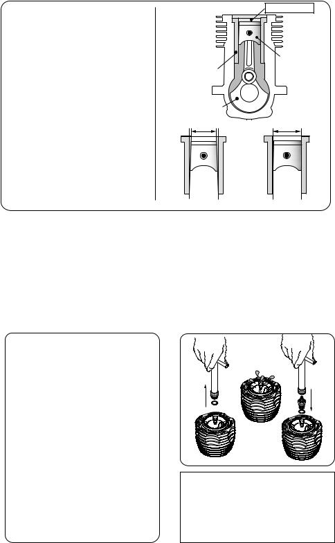
ENGINE CONSTRUCTION
With this engine, the piston
will feel tight at the top of its
Piston
stroke (TDC) when the engine
Cylinder Liner
is cold. This is normal. The cylinder bore has a slight
taper. The piston and cylinder
Crankshaft
are designed to achieve a
Slight taper
perfect running clearance when they reach operating temperature.
When the engine is cold. When the engine is hot.
6
NOTES WHEN APPLYING AN ELECTRIC STARTER
Do not over-prime. This could cause a hydraulic lock and damage the engine on application of the electric starter.
If over-primed, remove glowplug, close needle-valve and apply starter to pump out surplus fuel. Cover the head with a rag to prevent pumped out fuel getting into your eyes.
NOTE
As delivered, the engine has the carburetor lightly fit into its intake. Secure it changing its angle and outer head position according to the car chassis.
7
MAX-30VG(P) SERIES INSTRUCTIONS
This manual handles the following three versions.
 MAX-30VG(P)
MAX-30VG(P)-X (with recoil starter)  MAX-30VG(P) SR (for ROTO STARTER)
ABOUT THE ENGINE
These are rear exhaust and developed for mainly Monster Trucks. They are the largest displacement in the O.S. line up for model cars and offer overwhelming torque and power. The new 21E carburetor is a single adjustment type and fitted with a thermo insulator. It offers stable running.
The engine mount size is the same as the 21 size and easily replaced in most models.
 About MAX-30VG(P) SR
This engine is designed to utilize the SAVAGE ROTO STARTER System #87110 (for S-25 engine).
In case you own a SAVAGE ROTO STARTER System #87110, remove the back plate unit #87117 from the System and install it to the engine.
The back plate unit #87127 from the ROTO STARTER System #87126 for Nitro Star K Series cannot be installed to the engine. You need to purchase a back plate unit #87117 from HPI.
 SAVAGE, ROTO STARTER and Nitro Star are the product name of HPI RACING.
8
Standard accessories
For MAX-30VG(P) / MAX-30VG(P)-X
 Glow Plug No.8 1piece
 Exhaust Seal Ring 1piece
 Super Air Cleaner 203
Assembly
For MAX-30VG(P) SR
 Glow Plug No.8 1piece
 One-way Clutch 1piece
 Super Air Cleaner 203
Assembly
TOOLS, ACCESSORIES, etc.
The following items are necessary for operating the engine.
 Items necessary for starting
FUEL
Generally, it is suggested that the user selects a fuel that is commercially available for model two-stroke engines and contains 10-30% nitromethane.
As a starting point, we recommend a fuel containing 20% nitromethane, changing to a fuel containing more nitro if necessary. When the brand of fuel is changed, or the nitro content increased, it is advisable to repeat the running-in procedure referred to in the RUNNING-IN paragraphs. Please note that with high-nitro fuels, although power
may be increased for competition purposes, glowplug elements do not
last as long and engine life will be shorter.
REMINDER!
Model engine fuel is poisonous. Do not allow it to come into contact with the !eyes or mouth. Always store it in a
clearly marked container and out of the reach of children.
Model engine fuel is also highly flammable. Keep it away from open !flame, excessive heat, sources of sparks,
or anything else which might ignite it. Do not smoke or allow anyone else to smoke, near to it.
9

GLOWPLUG IGNITER
Commercialy available handy glowplug heater in which the glowplug battery and battery leads are integrated.
FUEL FILTER
To be installed in the fuel line between fuel tank and carburetor to prevent dust from entering the carburetor.
SILICONE FUEL LINE
Heatproof silicone tubing of approx. 5mm o.d. and 2mm i.d. is required for the connection between the fuel tank and engine.
 TOOLS
TOOLS
HEX SCREWDRIVER
Necessary for engine installation. 1.5mm, 2mm, 2.5mm, 3mm
SCREWDRIVER
STARTER BOX
For starting the engine. It is not necessary for 30VG(P)- X and 30VG(P)SR.
FUEL PUMP
For filling the fuel tank, a simple, polyethylene "squeeze" bottle, with a suitable spout, is required.
Necessary for carburetor adjustments. No.1, No.2, etc 

LONG SOCKET WRENCH WITH PLUG GRIP
Recommended for easy removal and replacement of the angled and recessed glowplug, the O.S.Long Socket Wrench incorporates a special grip.
10
BASIC ENGINE PARTS
Heatsink Head
Heatsink Head
Carburetor
Type 21E
Carburetor
Type 21E
|
Exhaust |
Exhaust |
|
|
Cover Plate |
Crankshaft |
|
|
Crankcase |
||
|
Crankcase |
||
|
|
||
|
Mounting Lugs |
Mounting Lugs |
|
Crankshaft Ball Bearing (Front) |
Rear Adaptor |
||
Starting Shaft |
|||
Crankshaft |
MAX-30VG(P) |
||
MAX-30VG(P) SR |
|||
11
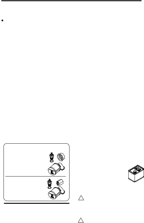
INSTALLATION OF THE STANDARD ACCESSORIES
 Installing the glow plug.
 Install the exhaust seal ring supplied.
Glowplug
Exhaust
Seal Ring
When the exhaust seal ring supplied cannot be fitted to the exhaust manifold you have, use a seal ring supplied with the car kit or the exhaust manifold.
 About the Head Gasket
These engines are equipped with two head gaskets of 0.2mm thick. It is suggested to adjust the total thickness according to atmospheric temperature, humidity and glowplug used.
 At early stage of running-in, when a glowplug tends to burn out early or when high nitromethane content fuel is used, try to run the engine with both gaskets or removing the 0.1mm gasket.
 When low nitromethane content fuel is used, try to run the engine removing one gasket.
12
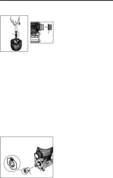
 MAX-30VG(P) SR
Exhaust seal ring is not supplied with the engine. Use an exhaust seal ring supplied with the car kit.
Installation of one-way clutch
 Inert the one-way clutch on the starting shaft with the O.S. and an arrow mark facing outside.
 Then, install the back plate unit #87117.
Starting Shaft
One-way Clutch
13
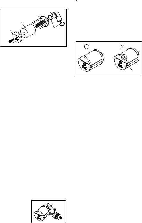
 AIR CLEANER TYPE 203
This is a heavy-duty wet type air cleaner that has been developed specifically for 3.5cc 'off-road' model car engines.
203 Intake Elbow |
|
Element Base |
|
Filter Element |
|
End Plate |
"O" Ring |
Retaining Screw |
|
NOTE:
The element is already impregnated with a special filter oil. As this oil is very sticky, take care, when handling it, to prevent dust or dirt from adhering to the element. If your fingers become contaminated, wash them with soap and water.
14
ASSEMBLY
Insert the filter element on the element base.
 Install the end plate with retaining screw, making sure that the element fits correctly between the end plate and base.
 Insert the joint pipe on the element base and secure it with "O" ring.
 Install the end plate, retaining screw, making sure that the element fits correctly between the end plate and base.
Element misaligned
REPLACMENT OF ELEMENT
NOTE:
During storage, the oil may have become unevenly dispersed through the element. This will be indicated if the blue color of the element material appears patchy. In this case, place the element in a small plastic bag and gently rub the element between finger and thumb to redistribute oil.
 It is advisable to replace the filter element after each hour of running time. Be careful not to allow dirt and dust to enter the carburetor.
INSTALLATION
 Carefully clean the carburetor, removing any old adhesive or sealant that may have been previously used on the outside of the air intake.
FURTHER PRECAUTIONS
When removing the air cleaner, check the inside of the element base and carburetor venturi. If any dirt is detected, this indicates that the filter element was incorrectly installed or should have been replaced earlier. In this event, it is vitally important to wash out the inside of the engine thoroughly, with alcohol or fuel, before it is used again, otherwise rapid wear of the piston/cylinder assenbly, bearings, connectingrod, etc., will occur. Obviously, it will be necessary to carry out the same procedure with the air cleaner and to replace the filter element.
NOTE:
Be careful not to splash alcohol or fuel over the filter element, or the filter oil will be washed away, and the filter capacity will be lowered.
15
 Loading...