


50SX
It is of vital importance, before attempting to
operate your engine, to read the general
'SAFETY INSTRUCTIONS AND WARNINGS'
section on pages 2-6 of this booklet and to strictly
adhere to the advice contained therein.
●
Also, please study the entire contents of this
instruction manual, so as to familiarize yourself
with the controls and other features of the
engine.
Keep these instructions in a safe place so that
you may readily refer to them whenever
necessary.
It is suggested that any instructions supplied
with the aircraft, radio control equipment, etc.,
are accessible for checking at the same time.
●
●

SAFETY INSTRUCTIONS AND
WARNINGS ABOUT YOUR O.S. ENGINE
FEATURES OF FX SERIES ENGINES, BEFORE
INSTALLING THE ENGINE
BASIC ENGINE PARTS
NEEDLE-VALVE LOCATION
INSTALLATION OF THE ENGINE
THROTTLE LINKAGE, SILENCER
FUEL T ANK LOCATION
GLOWPLUG
FUEL, PROPELLERS
MIXTURE CONTROLS
BEFORE STARTING
RUNNING-IN (Breaking-in)
IDLING ADJUSTMENT CHART
MIXTURE CONTROL VALVE ADJUSTMENT,
REALIGNMENT OF MIXTURE CONTROL VALVE
SUBSEQUENT STARTING PROCEDURE
SUBSEQUENT READJUSTMENT
CARBURETOR CLEANLINESS,
ENGINE CARE AND MAINTENANCE
ENGINE EXPLODED VIEWS &
ENGINE PARTS LISTS
CARBURETOR EXPLODED VIEWS
& PARTS LISTS
GENUINE O.S. PARTS & ACCESSORIES
ENGINE THREE VIEW DRAWINGS
MEMO
STARTING
CONTENTS
17
~
18
2
~
6
7
8
8
~
9
10
11
~
12
12
13
14
~
15
15
16
~
17
19
~
21
22
23
24
25
36
~
37
26
~
33
34
~
35
38
~
41
42
1

Remember that your engine is not a "toy", but a highly efficient internal-
combustion machine whose power is capable of harming you, or others, if it is
misused.
As owner, you, alone, are responsible for the safe operation of your engine, so act
with discretion and care at all times.
If at some future date, your O.S. engine is acquired by another person, we would
respectfully request that these instructions are also passed on to its new owner.
SAFETY INSTRUCTIONS AND WARNINGS ABOUT YOUR O.S. ENGINE
The advice which follows is grouped under two headings according to the
degree of damage or danger which might arise through misuse or neglect.
WARNINGS
NOTES
These cover events which
might involve serious (in
extreme circumstances, even
fatal) injury.
These cover the many other
possibilities, generally less obvious
sources of danger, but which, under
certain circumstances, may also
cause damage or injury.
2
WARNINGS
Model engine fuel is poisonous. Do not
allow it to come into contact with the eyes
or mouth. Always store it in a
clearly marked container and
out of the reach of children.
Never operate your engine in an en-
closed space. Model engines, like auto-
mobile engines, exhaust deadly carbon-
monoxide. Run your engine only in an
open area.
Model engines generate considerable
heat. Do not touch any part of your
engine until it has cooled. Contact with
the muffler (silencer),
cylinder head or exhaust
header pipe, in particular,
may result in a serious burn.
•
•
•
•
Never touch, or allow any object to come
into contact with, the rotating
propeller and do not crouch
over the engine when it is
running.
A weakened or loose propeller may
disintegrate or be thrown off and, since
propeller tip speeds with powerful
engines may exceed 600 feet(180 metres)
per second, it will be understood that
such a failure could result in serious
injury, (see 'NOTES' section relating to
propeller safety).
•
Model engine fuel is also highly
flammable. Keep it away from open flame,
excessive heat, sources of sparks, or
anything else which might ignite
it. Do not smoke or allow anyone
else to smoke, near to it.
•
3
NOTES
•
•
•
•
•
This engine was designed for model
aircraft. Do not attempt to use it for any
other purpose.
Mount the engine in your model securely,
following the manufacturers' recommenda-
tions, using appropriate screws and lock-
nuts.
Be sure to use the silencer (muffler)
supplied with the engine. Frequent
exposure to an open exhaust may
eventually impair your hearing.
Such noise is also likely to cause
annoyance to others over a wide area.
Install a top-quality propeller of the
diameter and pitch specified for the engine
and aircraft. Locate the propeller on the
shaft so that the curved face of the blades
faces forward-i.e. in the direction of flight.
Firmly tighten the propeller nut, using the
correct size wrench.
If you remove the glowplug from the engine
and check its condition by connecting the
battery leads to it, do not hold the plug with
bare fingers.Use an appropriate tool or a
folded piece of cloth.
4
NOTES
•
•
Always check the tightness of the propeller
nut and retighten it, if necessary, before
restarting the engine, particularly in the
case of four-stroke-cycle engines. If a
safety locknut assembly is provided with
your engine, always use it. This will prevent
the propeller from flying off in the event of a
"backfire", even if it loosens.
If you fit a spinner, make sure that it is a
precision made product and that the slots
for the propeller blades do not cut into the
blade roots and weaken them.
Preferably, use an electric starter. The
wearing of safety glasses is also strongly
recommended.
•
•
Discard any propeller which has become
split, cracked, nicked or otherwise rendered
unsafe. Never attempt to repair such a
propeller: destroy it. Do not modify a propeller
in any way, unless you are highly experienced
in tuning propellers for specialized
competition work such as pylon-racing.
Take care that the glow plug clip or battery
leads do not come into contact with the
propeller. Also check the linkage to the
throttle arm. A disconnected linkage could
also foul the propeller.
After starting the engine, carry out any
needle-valve readjustments from a safe
position behind the rotating propeller. Stop
the engine before attempting to make other
adjustments to the carburetor.
•
•
5

NOTES
•
•
•
•
•
Adjust the throttle linkage so that the engine
stops when the throttle stick and trim lever
on the transmitter are fully retarded.
Alternatively, the engine may be stopped by
cutting off the fuel supply. Never try to stop
the engine physically.
Take care that loose clothing (ties, shirt
sleeves, scarves, etc.)do not come into
contact with the propeller.Do not carry loose
objects (such as pencils, screwdrivers, etc.)
in a shirt pocket from where they could fall
through the propeller arc.
Do not start your engine in an area
containing loose gravel or sand.
The propeller may throw such material in
your face and eyes and cause injury.
For their safety, keep all onlookers
(especially small children) well back (at
least 20 feet or 6 meters) when preparing
your model for flight. If you have to carry
the model to the take-off point with the
engine running, be especially cautious.
Keep the propeller pointed away from you
and walk well clear of spectators.
Warning! Immediately after a glowplug-
ignition engine has been run and is still
warm, conditions sometimes exist whereby
it is just possible for the engine to abruptly
restart if the propeller is casually flipped
over compression WITHOUT the glowplug
battery being reconnected. Remember this
if you wish to avoid the risk of a painfully
rapped knuckle!
6
This range of engines is ideally suited to a variety
of R/C aircraft, including trainer, sports, aerobatic
and scale types.
A separate precision-made needle-valve unit is
installed at the rear, where manual adjustment is
safely remote from the rotating propeller.
With the 50SX, 61FX and 91FX, the needle-valve
assembly can be installed either horizontally or
vertically.
FEATURES OF FX SERIES ENGINES
With these engines, the piston will feel tight at the
top of its stroke when the engine is cold. This is
normal. The piston and cylinder are designed to
achieve a perfect running clearance when they
reach their intended running temperature.
Note :
•
•
•
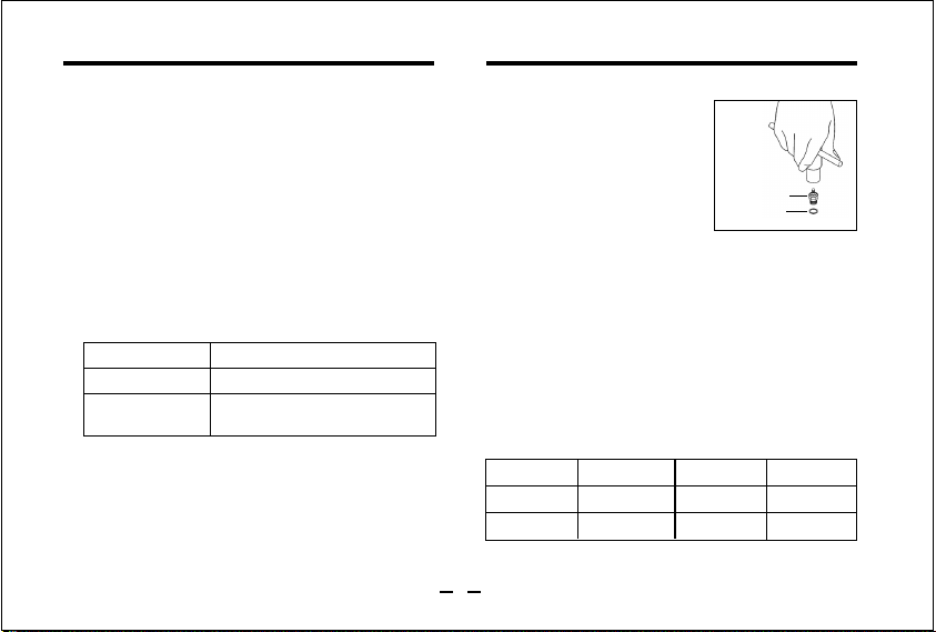
Carefully insert plug, with
washer, fingertight only, before
final tightening with the correct
size plug wrench.
BEFORE INSTALLING THE ENGINE
Installing the glowplug
Connect the short length of fuel tubing (supplied)
securely between the needle-valve outlet and
carburetor inlet as shown in the illustration on the
next page.
In the event of the tubing becoming damaged, it
should be replaced with a suitable length (as
indicated below) of best quality 5mm ODx2mm ID
silicone tubing. Use similar material to connect the
fuel inlet nipple to the fuel tank.
Connecting fuel tubing
Length
40
¡
46FX
54
~
56mm 61FX
91FX
54
~
56mm
62mm
Glow plug
Washer
50SX
44
~
46mm
Length
Glow Plug No.8, Silicone Tube, Instruction Manual
Common to accessories
50SX, 40/46FX
61FX
91FX
873 Silencer Assembly
E-4010 Silencer Assembly
E-4020 Silencer Assembly
Needle Valve Extension Cable
Type of engines
Type of engines
7
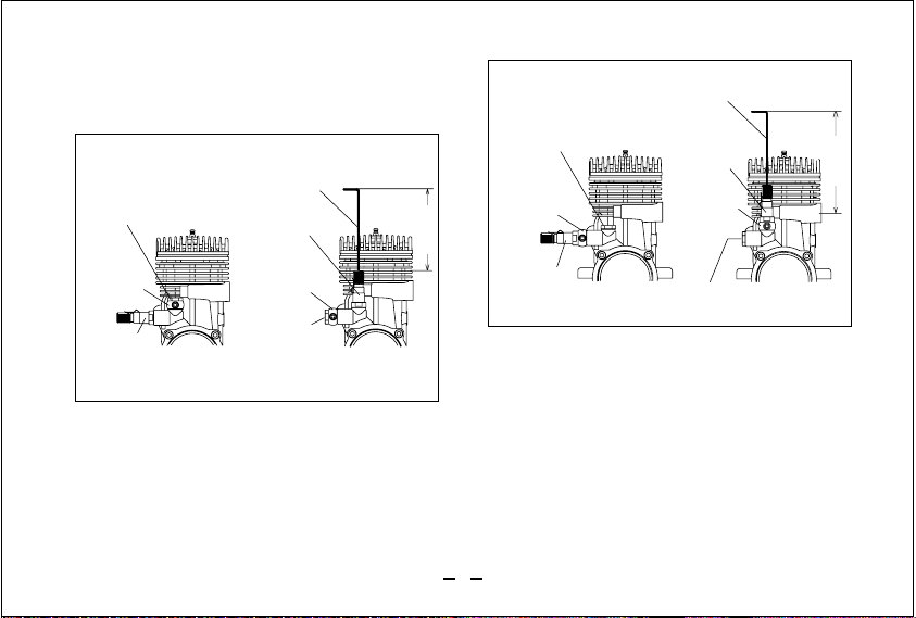
The proce
dure for relocating the needle-valve vertically
is as follows:
As delivered from the factory, the MAX-61FX and
MAX-91FX
RING have their needle-valve assembly
installed horizontally. However, if more convenient for
a particular installation, the needle-valve may be
reinstated vertically behind the cylinder. (See sketch
opposite.) Please note that the needle-valve knob
has a center hole and set-screw for the fitting of a
piano-wire extension (supplied with the 91FX) so that,
when relocated vertically, the extension enables
adjustments to be made without risk of burning one's
fingers on the cylinder head.
NEEDLE-VALVE LOCATION
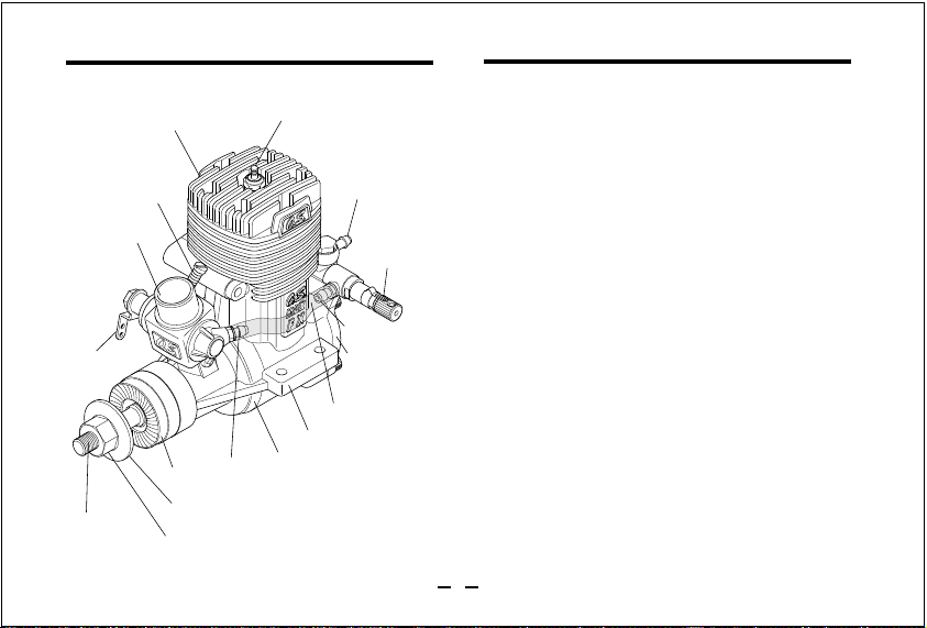
BASIC ENGINE PARTS
Cylinder head
Carburetor
Silicone Tube
Crankshaft
Propeller nut
Propeller washer
Drive Hub
Crankcase
Needle valve
Cover Plate
Fuel outlet
Fuel inlet
Glowplug
Fuel inlet
Beam Mount
MAX-61FX
Throttle
Lever
Throttle Stop Screw
Using 8mm wrench, remove complete needle-valve
holder assembly including needle, from side of
cover plate.
Remove fuel inlet assembly from upper boss of
cover plate.
Transfer banjo type fuel inlet including washers, to
needle-valve holder and carefully screw complete
assembly into upper boss vacated by fuel inlet
assembly. Tighten very carefully.
1.
2.
3.
8
Inlet Holder
Plug Screw (50SX/91FX)
Fuel Inlet
Needle-Valve
Assembly
Needle Extension
Inlet Holder
Fuel Inlet
Needle-Valve
Assembly
45mm
Fuel Inlet
Needle-Valve
Assembly
Plug Screw (50SX/91FX)
Fuel Inlet
Needle-Valve
Assembly
Needle Extension
45mm
61FX
50SX/91FX
Use hexagon-head brass inlet holder (61FX) or
plug screw (50SX/91FX) to blank off side boss
vacated by needle- valve assembly.
4.
9
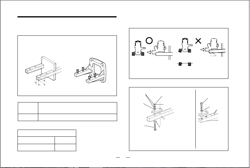
Hardwood mounting beams
O.S. radial motor
mount
(cast aluminum)
How to fasten the mounting screws.
Make sure that the mounting beams are parallel and
that their top surfaces are in the same plane.
Front view Side view
Top surfaces
are not in the
same plane.
Opposite
beam
Top surfaces
are not in the
same plane.
Re-align the surfaces
as necessary
Engine does not
rest firmly.
CORRECT INCORRECT
Top surfaces are in
the same plane.
Tighten second
nut firmly down
onto first nut.
Tighten this
nut first.
Steel washer
3-4mm
steel screw
Spring
washer or
lock washer
Hardwood such
as cherry or maple.
Spring
washer
3.5mm steel
Allen screw
3-4mm steel nuts
Use mounting screws of a diameter
(between 3mm and 4mm) appropriate
to engine size (see table left).
Mounting Screw Size
50SX, 40
¡
46FX
61
¡
91FX
3mm
4mm
INSTALLATION OF THE ENGINE
Rigid hardwood
(e.g. maple)
At least
15mm(5/8")
At least
15mm(5/8")
O.S. radial motor mount
(Available as an optional extra
part. See parts list)
A typical method of beam
mounting is shown below, left.
Installation in the model
50SX
40
¡
46FX
61
¡
91FX
For 50SX, 40/46FX(Code No. 71913100)
For 60FP, 61
¡
91FX(Code No. 71905200)
10
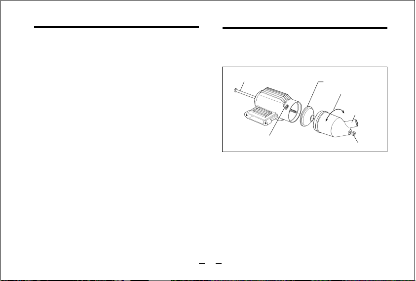
The exhaust outlet of the silencer can be rotated to
any desired position in the following manner:
Loosen the locknut and assembly screw.
Set the exhaust outlet at the required position by
rotating the rear part of the silencer.
Re-tighten the assembly screw, followed by the
locknut.
SILENCER
1)
2)
3)
NOTE :
The standard expansion-chamber type silencer is
quite effective, but reduces power to some degree.
Assembly screw
Cone baffle
Turn to requlred position
Exhaust outlet
Locknut
Exhaust pressure nipple
Before connecting the throttle-lever/servo linkage,
make sure that no part of the linkage interferes with
the internal structure of the aircraft or wiring, etc.,
when the throttle is fully open or fully closed.
Set the throttle lever linkage so that the throttle ro-
tor is (a) fully open when the transmitter throttle
stick is fully advanced and (b) fully closed when
the throttle stick is fully retarded.
Adjustment of the throttle rotor opening at the idling
position can then be made with the throttle trim lev-
er on the transmitter.
(Select throttle-lever and servo-horn hole positions
that will avoid excessive pushrod travel causing the
throttle to bind at either end.)
THROTTLE LINKAGE
When adjusting the throttle lever angle, relative to
the rotor,hold the rotor at about half-way between
the open and closed positions while loosening
and tightening the fixing screw, otherwise the
rotor, rotor guide screw,throttle stop screw or
carburettor body may become burred and
damaged.
Note:
•
•
E-4010 Silencer
11
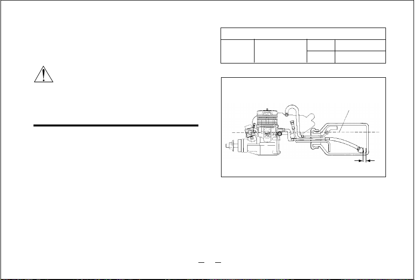
Suggested fuel tank capacities are listed opposite.
These will allow 12-13 minute flights.
Locate the fuel tank so that the top of the tank is 5-
10mm (1/4-3/8") above the level of the needle-valve.
Be sure to use a pressurized fuel system by
connecting the muffler pressure nipple to the vent-
pipe of the fuel tank.
Suggested Fuel Tank Capacities
50SX
40
¡
46FX
approx 300cc
approx 350cc
approx 450cc
61FX
91FX
FUEL TANK LOCATION
Attention to tank height
•
Fuel level
10mm
Model engines generate considerable heat.
Do not touch any part of your engine until
it has cooled.
Contact with the muffler (silencer), cylinder
head or exhaust header pipe, in particular,
may result in a serious burn.
Keep your hands and face away from
exhaust gas or you will suffer a burn.
Reminder!
12
 Loading...