


It is of vital importance, before attempting to operate your engine, to read the general
'SAFETY INSTRUCTIONS AND WARNINGS' section on pages 2-4 of this booklet and to strictly adhere to the advice contained therein.
 Also, please study the entire contents of this instruction manual, so as to familiarize yourself with the controls and other features of the engine.
 Keep these instructions in a safe place so that you may readily refer to them whenever necessary.
 It is suggested that any instructions supplied with the aircraft, radio control equipment, etc., are accessible for checking at the same time.
Horizontally-opposed twin-cylinder overhead-valve four-stroke-cycle
CONTENTS
SAFETY INSTRUCTIONS AND |
2-4 |
|
22 |
WARNINGS ABOUT YOUR O.S. ENGINE |
FLIGHT |
||
INTRODUCTION, TOOLS AND ACCESSORIES |
5 |
CARE AND MAINTENANCE |
22 |
ENGINE PARTS NAME |
6-7 |
VALVE CLEARANCE ADJUSTMENT |
23-25 |
|
|
|
|
INSTALLATION, |
8-10 |
ENGINE EXPLODED VIEW |
26 |
PROPELLER, FUEL TANK |
10-11 |
ENGINE PARTS LIST |
27 |
GLOWPLUGS, |
12 |
CARBURETOR EXPLODED VIEW & |
|
|
|
PARTS LIST |
28 |
GLOWPLUG HEATING |
13-14 |
|
|
|
|
O.S. GENUINE PARTS & ACCESSORIES |
29 |
FUEL AND LUBRICATION, STARTING |
15-18 |
|
|
|
|
ENGINE THREE VIEW DRAWINGS |
30 |
RUNNING-IN ("Breaking-in") |
18-19 |
|
|
THROTTLE VALVE ADJUSTMENT |
19-21 |
|
|
1
SAFETY INSTRUCTIONS AND WARNINGS ABOUT YOUR O.S. ENGINE
Remember that your engine is not a " toy ", but a highly efficient internal-combustion machine whose power is capable of harming you, or others, if it is misused or abused. As owner, you, alone, are responsible for the safe operation of your engine, so act with discretion and care at all times.
If at some future date, your O.S. engine is acquired by another person, we would respectfully request that these instructions are also passed on to its new owner.
The advice which follows is grouped under two headings according to the degree of damage or danger which might arise through misuse or neglect.
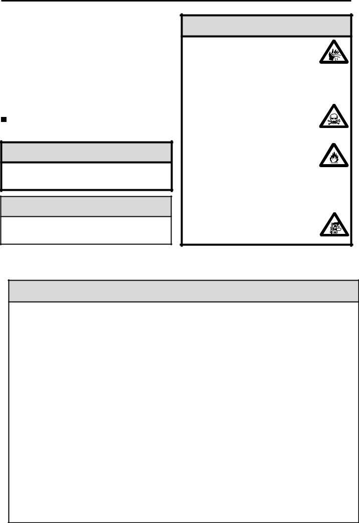
 WARNINGS
These cover events which might involve serious ( in extreme circumstances, even fatal ) injury.
 NOTES
NOTES
These cover the many other possibilities, generally less obvious sources of danger, but which, under certain circumstances, may also cause damage or injury.
 WARNINGS
 Never touch, or allow any object to come into contact with, the rotating propeller and do not crouch over the engine when it is running.
 A weakened or loose propeller may disintegrate or be thrown off and, since propeller tip speeds with powerful engines may exceed 600 feet(180 metres) per second, it will be understood that such a failure could result in serious injury, (see 'NOTES' section relating to propeller safety).
 Model engine fuel is poisonous. Do not allow it to come into contact with the eyes or mouth. Always store it in a clearly marked container and out of the reach of children.
 Model engine fuel is also highly flammable. Keep it away from an open flame, excessive heat, sources of sparks, or anything else which might ignite it.
Do not smoke or allow anyone else to smoke, near to it.
 Never operate your engine in an enclosed space. Model engines, like automobile engines, exhaust deadly carbonmonoxide. Run your engine only in an open area.
 Model engines generate considerable heat. Do not touch any part of your engine until it has cooled. Contact with the muffler(silencer), cylinder head or exhaust header pipe, in particular, may result in a serious burn.
2
 NOTES
NOTES
 This engine was designed for model aircraft. Do not attempt to use it for any other purpose.
 Mount the engine in your model securely, following the manufacturers' recommendations, using appropriate screws and locknuts.
 Be sure to use the silencer (muffler) supplied with the engine. Frequent exposure to an open exhaust may eventually impair your hearing.
Such noise is also likely to cause annoyance to others over a wide area.
 If you remove the glowplug from the engine and check its condition by connecting the battery leads to it, do not hold the plug with bare fingers.Use an appropriate tool or a folded piece of cloth.
 Install a top-quality propeller of the diameter and pitch specified for the engine and aircraft. Locate the propeller on the shaft so that the curved face of the blades faces forward-i.e. in the direction of flight. Firmly tighten the propeller nut, using the correct size wrench.
 Always check the tightness of the propeller nut and retighten it, if necessary, before restarting the engine, particularly in the case of four-stroke-cycle engines. If a safety locknut assembly is provided with your engine, always use it. This will prevent the propeller from flying off in the event of a "backfire", even if it loosens. Also, check the tightness of all the screws and nuts before restarting the engine.
 If you install a spinner, make sure that it is a precision made product and that the slots for the propeller blades do not cut into the blade roots and weaken them.
 Discard any propeller which has become split, cracked, nicked or otherwise rendered unsafe. Never attempt to repair such a propeller: destroy it. Do not modify a propeller in any way, unless you are highly experienced in tuning propellers for specialized competition work such as pylon-racing.
3
 NOTES
NOTES
 Use an electric starter for this engine. The wearing of safety glasses is also strongly recommended.
 Take care that the glow plug clip or battery leads do not come into contact with the propeller. Also check the linkage to the throttle arm. A disconnected linkage could also foul the propeller.
 After starting the engine, carry out any needle-valve readjustments from a safe position behind the rotating propeller. Stop the engine before attempting to make other adjustments to the carburetor.
 Adjust the throttle linkage so that the engine stops when the throttle stick and trim lever on the transmitter are fully retarded. Alternatively, the engine may be stopped by cutting off the fuel supply. Never try to stop the engine physically.
 Take care that loose clothing (ties, shirt sleeves, scarves, etc.) do not come into contact with the propeller.
Do not carry loose objects (such as pencils, screwdrivers, etc.) in a shirt pocket from where they could fall through the propeller arc.
 Do not start your engine in an area containing loose gravel or sand. The propeller may throw such material in your face and eyes and cause injury.
 For their safety, keep all onlookers (especially small children) well back (at least 20 feet or 6 meters) when preparing your model for flight. If you have to carry the model to the take-off point with the engine running, be especially cautious. Keep the propeller pointed away from you and walk well clear of spectators.
 Warning! Immediately after a glowplug-ignition engine has been run and is still warm, conditions sometimes exist whereby it is just possible for the engine to abruptly restart if the propeller is casually flipped over compression WITHOUT the glowplug battery being reconnected. Remember this if you wish to avoid the risk of a painfully rapped knuckle!
4
|
INTRODUCTION |
|
|
|
|
|
|
||
|
The O.S. FT-300 (Super Gemini-300) is a horizontally- |
|
|
|
|||||
|
opposed twin-cylinder overhead-valve four-stroke- |
|
|
|
|||||
|
cycle engine of 48.76cc (2.976cu.in) displacement. |
|
|
|
|||||
|
The horizontally-opposed layout, typical of modern |
|
|
7 |
|||||
|
light aircraft engine design, provides very smooth |
|
|
||||||
|
|
|
|
||||||
|
running qualities and docile, trouble-free handling |
|
3 |
2 |
|||||
|
characteristics. |
|
|
|
|
||||
|
|
|
|
|
|
|
|||
|
|
|
|
|
|
|
|||
|
Photos and illustrations in this manual show FT-160. |
|
|
|
|
||||
|
It's appearance a little differs from that of FT-300. |
|
|
4-2 |
|
||||
|
|
|
|
|
|
|
|||
|
|
|
|
|
|
|
|||
|
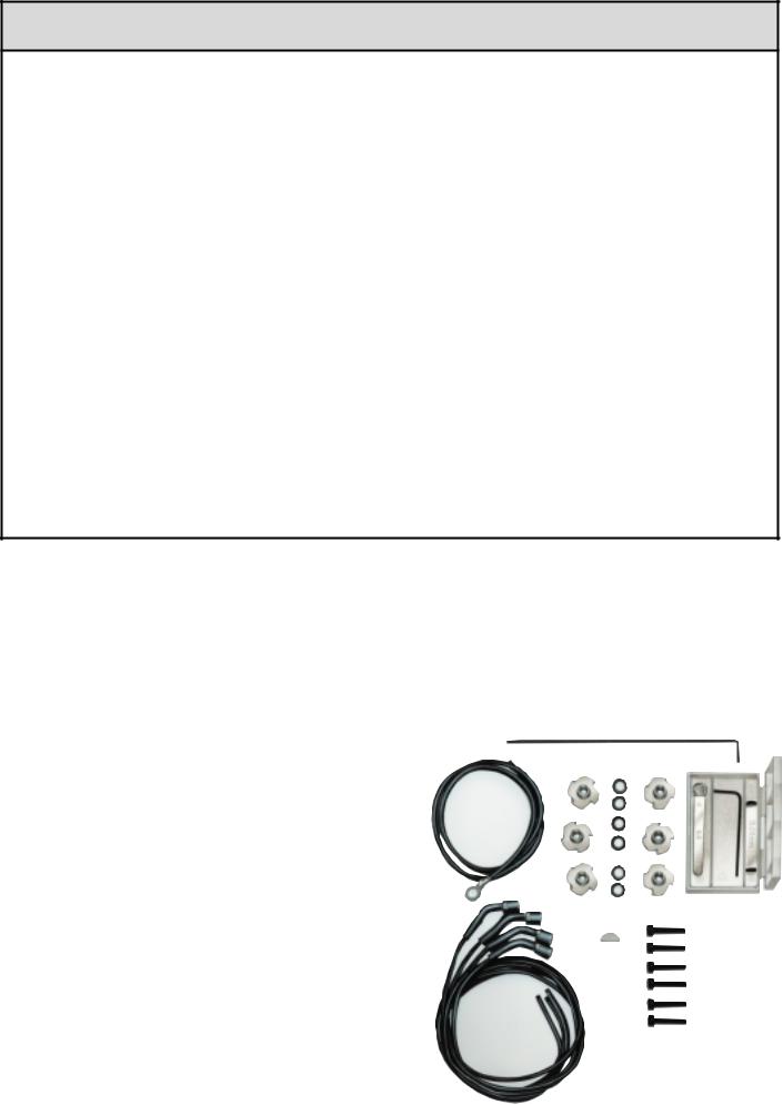
TOOLS AND ACCESSORIES |
|
|
|
|||||
|
The following tools and accessories are |
supplied with your |
4 |
|
6 |
||||
|
engine. |
|
|
|
|
|
|
|
|
|
|
|
|
|
|
|
|
|
5 |
|
No. |
|
Description |
|
Quantity |
|
|
|
|
|
1 |
|
Mount fixing screw (M5X25) |
|
6 |
|
|
|
|
|
2 |
|
Lock washers (ø 5) |
|
6 |
|
|
|
|
|
3 |
|
Blind nuts (M5) |
|
6 |
|
|
4-1 |
1 |
|
|
|
Set of leads for wiring glow plugs |
|
|
|
|
||
|
4 |
|
|
|
|
|
|
||
|
|
|
|
|
|
|
|
||
|
4-1 |
|
Leads for glow plug with clip |
|
2 |
|
|
|
|
|
4-2 |
|
Lead for earth (ground) |
|
1 |
|
|
|
|
|
5 |
|
Woodruff key |
|
1 |
|
|
|
|
|
6 |
|
Valve adjusting tool kit |
|
1 |
|
|
|
|
|
7 |
|
Choke valve rod |
|
1 |
|
|
|
Photo 1 |
|
|
|
|
|
|
|
|
|
|
5

ENGINE PARTS NAME |
Photo. 2 |
|
Right (No.2) Cylinder |
||
|
||
|
Crankcase |
|
Aluminum tube |
Left (No.1) Cylinder |
|
|
Cylinder Head |
|
|
Glow Plug |
|
|
Rocker Cover |
|
Propeller Nut |
|
Lock Nut
Propeller Washer |
|
Drive Hub |
Exhaust Pipe |
|
Carburetor |
|
Photo shows FT-160. |
|
Aluminum tube is not supplied with the engine. |
6
Photo. 3
Choke Valve
Intake Manifold |
Fuel Inlet |
Push Rod Cover
Breather Nipple
Intake Pipe (Right) |
Intake Pipe (Left) |
Rear Housing
Photo shows FT-160.
7

INSTALLATION
 It is essential that the firewall is strong and rigid (e.g. at least 15mm thick) and firmly integrated with the structure of the aircraft.
 In the interests of scale appearance, the engine should be installed with the carburetor below the crankcase so that the exhaust pipes point downwards.
Note:
Make sure that the firewall is all flush and front face and rear face are parallel. Do not dismantle the engine from the radial mount when installing the radial mount to the firewall.
Before installing the engine on the radial mount after dismantling it from the mount, make sure both arms are flush and parallel.
Firewall
M5x25
 5
5
Fig. 1
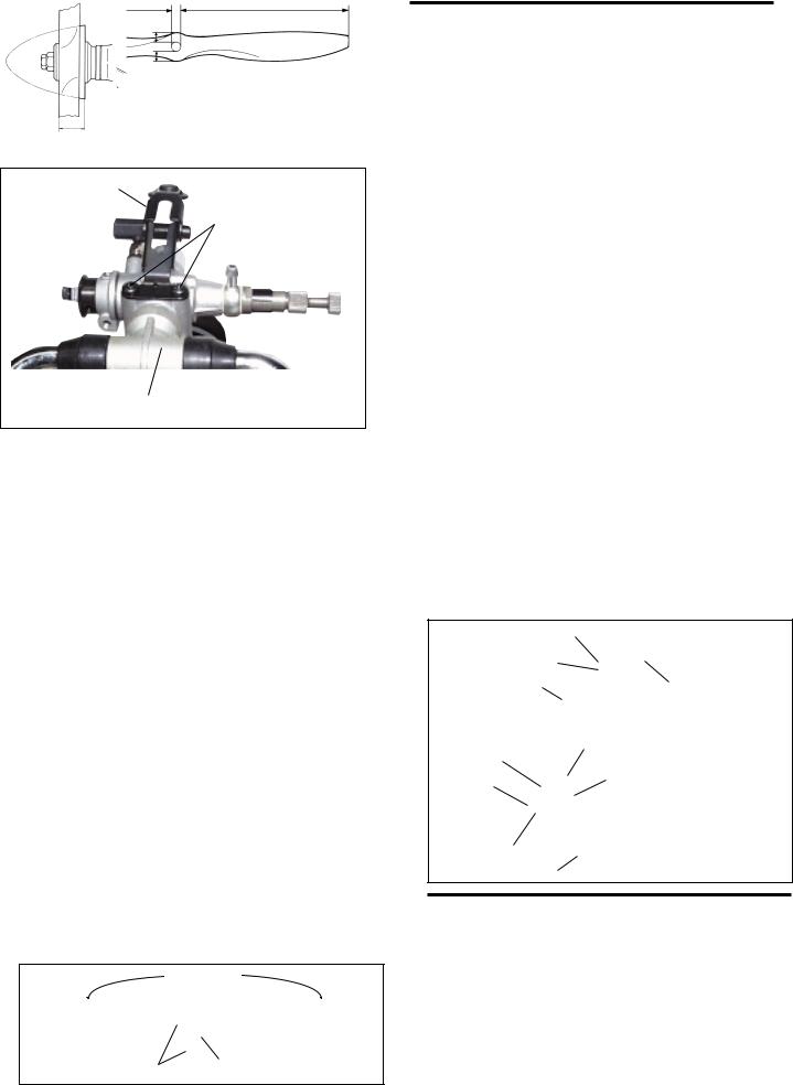
Needle-valve extension
 The needle-valve with this engine is designed to incorporate an extension so that, when the engine is enclosed within the fuselage, the needle-valve may be adjusted from the outside. An L-shaped rod, of 1.6-1.8mm dia. and
appropriate length, should be inserted into the needle's centre hole and secured by tightening the set-screw in the needle-valve knob with the small Allen key provided. For longer extension, it is recommended to use the extension cable with the engine, together with the knob and support hook also. For this purpose, Needle Valve Extension Cable Set (Code No. 72200080) is available as an optional part.
 Do not use an excessively long unsupported extension as this may vibrate and cause the needle-valve setting to vary or even damage the needle-valve thread. Always provide a suitable support at the outer end.
Set-screw
Needle |
Cable |
Knob |
|
|
Fig. 2
8
Choke valve
The choke valve operating lever can be located rught or left by reversing the hexagon nut nd cap screw.
 Unscrew the cap screw while holding the hexagon nut with 6mm wrench, and re-fit the lever to required location.
 If the rod is too long, reduce it to required length.
 A needlessly lengthy rod may vibrete. The rod should be as short as possible or have its outer end supported.
|
Set-screw |
Fig. 3 |
|
|
|
|
|
Cap screw |
Choke lever |
Hex. nut |
Choke rubber pad |
|
|
|
|
|
|
Fuel inlet
The fuel inlet nipple on the carburetor can be adjusted to the most suitable position for connecting to the fuel delivery tube from the tank. Slacken the needle-valve holder with the 8mm wrench provided, reset the inlet nipple at the required angle and re-tighten.
Fuel inlet
Slacken with 8mm wrench
Needle-valve
Fig. 4
Exhaust pipe adjustment
 The direction of the exhaust pipes may be altered in accordance with individual installation requirements. The angle is easily adjusted by loosening the nut that secures the exhaust pipe to the cylinder head. Use the 12mm wrench supplied.
Fig. 5
12mm wrench
Tighten
Loosen
Lock nut
Exhaust pipe
Carburetor cleanliness
 It is recommended that the fuel is passed through a filter when the tank is filled and that a good in-line filter is installed between the fuel tank and carburetor.
 Occasionally remove the needle-valve holder from the carburetor and rinse out the locaions shown in Fig. 6 and Fig. 7 with methanol or fuel. Be careful not to lose the gasket when removing the needle-valve holder from the carburetor.
Fig. 6 |
Squeeze bottle |
Fig. 7 |
Dirt and fibrous matter mostly accumulate here.
Dirt and fibrous matter mostly accumulate here.
Needle-valve holder
9
Carburetor
The needle-valve and throttle lever locations are interchangeable by reversing the carburetor. This can be done as follows:
Remove the carburetor carefully by unscrewing the two screws which secure both carburetor and choke valve.
After reversing the carburetor, re-insert it into the intake manifold, taking care not to damage the O-ring in the manifold.
Choke valve |
Photo. 4 |
|
Carburetor retaining screw
Intake manifold
10
PROPELLER
The choice of propeller depends on the design and weight of the aircraft and on the type of flying in which you will be engaged. Determine the best size and type after practical experimentation. As a starting point, refer to the props listed in the accompanying table. Slightly larger, or even slightly smaller, props than those shown in the table may be used, but remember that propeller noise will increase if blade tip velocity is raised, due to higher rpm or if a larger-diameter / lower-pitch prop is used.
Warning:
Make sure that the propeller is well balanced. An unbalanced propeller and / or spinner can cause serious vibration which may weaken parts of the airframe or affect the safety of the radio-control system.
DO NOT forget the WARNINGS and NOTES on propeller and spinner safety given on pages 2,3 and 4.
Type |
Size (DxP) |
|
|
Sport/Scale |
18x10-12, 20x8-10, 22x8 |
|
|
NOTE:
Make a habit of always checking the tightness of the propeller before starting the engine. Remember that, especially with wooden propellers, there is a tendency for the material to shrink, or for it to be reduced by the serrated face of the drive hub. Retighten the propeller nut if necessary after loosening the Safety Propeller Locknut. The licknut should be tightened firmly after retightening the propeller nut.
PROPELLER & SPINNER ATTACHMENT
There is a risk, particularly with powerful four-stroke engines, of the propeller flying off if the prop nut loosens due to detonation ("knocking") in the combustion chamber when the engine is operated too lean, or under an excessively heavy load.
Obviously, this can be very hazardous. To eliminate such dangers, the O.S. Safety Locknut Assembly was devised. Install this as follows:
1.Ream the propeller shaft hole to 13.5mm bore with an appropriate reamer, checking that the hole is exactly centered.
2.Install the prop to the engine shaft, followed by the retaining washer and prop nut and tighten firmly with a 17mm wrench. (not supplied).
3.Add the special tapered and slotted locknut and secure with a 13.5mm wrench while holding the prop nut with the 14mm wrench. (not supplied).
To be equal |
Fig. 8 |
To be equal |
Ream to 13.5mm dia. |
|
Propeller washer
Propeller nut
Locknut
Propeller washer
Locknut
Propeller nut
Fig. 9
Drive hub
Back-plate of spinner
Drive hub
The Safety Propeller Locknut can be used provided that the width is between 21.5mm and 26mm.
FUEL TANK
The suggested fuel tank size is 400cc or 14 oz. This will give approximately 10 minutes running time at full power, or about 13-15 minutes when some part-throttle operation is included. Fuel consumption also depends, of course, on the size of propeller used.
The ideal fuel tank location is with the top of the tank 5-10mm (1/4-3/8") above the needle valve. However, model design will usually require the tank to be located higher than this and there should be no trouble with such a tank location provided that you do not pursue spectacular aerobatic flight.
If the tank is located high, fuel will flow into the carburetor when the tank is full. Therefore, pinch the fuel line with a clip, when the engine is not running, to prevent flooding and loss of fuel.
11
 Loading...