


It is of vital importance, before attempting to operate your engine, to read the general
'SAFETY INSTRUCTIONS AND WARNINGS' section on pages 2-6 of this booklet and to strictly adhere to the advice contained therein.
●Also, please study the entire contents of this instruction manual, so as to familiarize yourself with the controls and other features of the engine.
●Keep these instructions in a safe place so that you may readily refer to them whenever necessary.
●It is suggested that any instructions supplied with the aircraft, radio control equipment, etc., are accessible for checking at the same time.

CONTENTS
SAFETY INSTRUCTIONS AND WARNINGS |
2~6 |
RUNNING -IN |
21 |
|
ABOUT YOUR O.S. ENGINE |
|
CARBURETOR |
22~23 |
|
|
|
|||
INTRODUCTION,BASIC ENGINE PARTS |
7 |
CARBURETOR AIR-BLEED ADJUSTMENT |
24 |
|
|
|
|||
INSTALLATION |
8 |
TROUBLE SHOOTING WHEN THE |
|
|
|
|
25~26 |
||
INSTALLATION OF CHOKE ROD, NEEDLE VALVE |
|
ENGINE FAILS TO START |
||
EXTENSION, EXHAUST PIPE ADJUSTMENT(FS-26S) |
9 |
VALVE ADJUSTING |
27~29 |
|
|
|
|||
SILENCER, |
|
CARE AND MAINTENANCE |
30 |
|
LINKAGE OF THROTTLE LEVER |
10 |
|||
BEFORE STARTING |
11~12 |
THREE VIEW DRAWING |
31 |
|
FUEL AND PRESSURE LINES |
12 |
ENGINE EXPLODED VIEW |
32~35 |
|
|
|
|||
ADVICE ON SELECTION OF FUEL, |
|
CARBURETOR EXPLODED VIEW |
|
|
13~14 |
& PARTS LIST |
36 |
||
GLOEPLUG & PROPELLER |
||||
|
|
|||
STARTING THE ENGINE |
15~21 |
GENUINE PARTS & ACCESSORIES |
37 |
|
|
|
|||
|
|
MEMO |
38 |
1

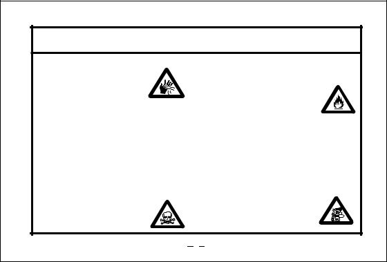
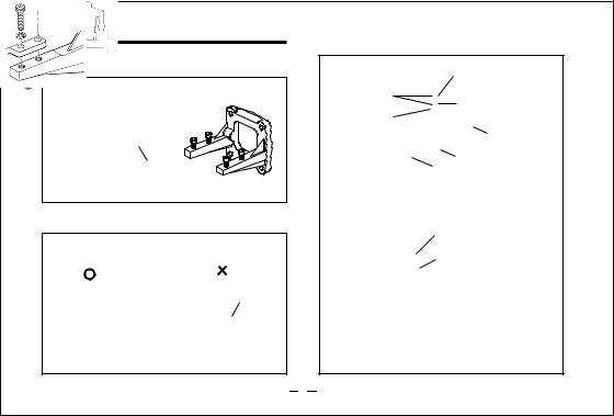
SAFETY INSTRUCTIONS AND WARNINGS ABOUT YOUR O.S. ENGINE
Remember that your engine is not a "toy", but a highly efficient internalcombustion machine whose power is capable of harming you, or others, if it is misused.
As owner, you, alone, are responsible for the safe operation of your engine, so act with discretion and care at all times.
If at some future date, your O.S. engine is acquired by another person, we would respectfully request that these instructions are also passed on to its new owner.
 The advice which follows is grouped under two headings according to the degree of damage or danger which might arise through misuse or neglect.
 WARNINGS
These cover events which might involve serious (in extreme circumstances, even fatal) injury.
 NOTES
NOTES
These cover the many other possibilities, generally less obvious sources of danger, but which, under certain circumstances, may also cause damage or injury.
2
 WARNINGS
•Never touch, or allow any object to come into contact with, the rotating
propeller and do not crouch over the engine when it is running.
•A weakened or loose propeller may disintegrate or be thrown off and, since propeller tip speeds with powerful engines may exceed 600 feet(180 metres) per second, it will be understood that such a failure could result in serious injury, (see 'NOTES' section relating to propeller safety).
•Model engine fuel is poisonous. Do not allow it to come into contact with the eyes or mouth. Always store it in a
clearly marked container and
out of the reach of children.
•Model engine fuel is also highly flammable. Keep it away from open flame, excessive heat, sources of sparks, or anything else which might ignite
it. Do not smoke or allow anyone else to smoke, near to it.
•Never operate your engine in an enclosed space. Model engines, like automobile engines, exhaust deadly carbonmonoxide. Run your engine only in an open area.
•Model engines generate considerable heat. Do not touch any part of your engine until it has cooled. Contact with the muffler (silencer),
cylinder head or exhaust header pipe, in particular, may result in a serious burn.
3
NOTES
•This engine was designed for model aircraft. Do not attempt to use it for any other purpose.
•Mount the engine in your model securely, following the manufacturers' recommendations, using appropriate screws and locknuts.
•Be sure to use the silencer (muffler) supplied with the engine. Frequent exposure to an open exhaust may eventually impair your hearing.
Such noise is also likely to cause annoyance to others over a wide area.
•If you remove the glowplug from the engine and check its condition by connecting the battery leads to it, do not hold the plug with bare fingers.Use an appropriate tool or a folded piece of cloth.
•Install a top-quality propeller of the diameter and pitch specified for the engine and aircraft. Locate the propeller on the shaft so that the curved face of the blades faces forward-i.e. in the direction of flight. Firmly tighten the propeller nut, using the correct size wrench.
4

NOTES
•Always check the tightness of the propeller nut and retighten it, if necessary, before restarting the engine, particularly in the case of four-stroke-cycle engines. If a safety locknut assembly is provided with your engine, always use it. This will prevent the propeller from flying off in the event of a "backfire", even if it loosens.
•If you install a spinner, make sure that it is a precision made product and that the slots for the propeller blades do not cut into the blade roots and weaken them.
•Preferably, use an electric starter. The wearing of safety glasses is also strongly recommended.
•Discard any propeller which has become split, cracked, nicked or otherwise rendered unsafe. Never attempt to repair such a propeller: destroy it. Do not modify a propeller in any way, unless you are highly experienced in tuning propellers for specialized competition work such as pylon-racing.
•Take care that the glow plug clip or battery leads do not come into contact with the
propeller. Also check the linkage to the throttle arm. A disconnected linkage could also foul the propeller.
•After starting the engine, carry out any needle-valve readjustments from a safe
position behind the rotating propeller. Stop the engine before attempting to make other adjustments to the carburettor.
5
NOTES
•Adjust the throttle linkage so that the engine stops when the throttle stick and trim lever on the transmitter are fully retarded. Alternatively, the engine may be stopped by cutting off the fuel supply. Never try to stop the engine physically.
•Take care that loose clothing (ties, shirt sleeves, scarves, etc.)do not come into contact with the propeller.Do not carry loose objects (such as pencils, screwdrivers, etc.) in a shirt pocket from where they could fall through the propeller arc.
•Do not start your engine in an area containing loose gravel or sand.
The propeller may throw such material in your face and eyes and cause injury.
•For their safety, keep all onlookers (especially small children) well back (at least 20 feet or 6 meters) when preparing your model for flight. If you have to carry the model to the take-off point with the engine running, be especially cautious. Keep the propeller pointed away from you and walk well clear of spectators.
•Warning! Immediately after a glowplugignition engine has been run and is still warm, conditions sometimes exist whereby it is just possible for the engine to abruptly restart if the propeller is casually flipped over compression WITHOUT the glowplug battery being reconnected. Remember this if you wish to avoid the risk of a painfully rapped knuckle!
6
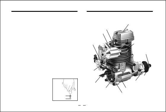
INTRODUCTION
The FS Series engines are up-to-date overhead-valve four-stroke-cycle engines for model aircraft use and are the outcome of a long period of technical development. The FS Series engines are produced by the world's oldest and largest model engine manufacturing company; a company which also pioneered the quantity production of model four-cycle engines.
Accessories
FS-26S |
FS-40S |
•Silencer Body |
•Silencer Assembly |
•Choke rod |
•Choke rod |
•Silicone tubing |
•Silicone tubing |
INSTALLING THE GLOWPLUG |
|
Install washer on glowplug and |
|
insert carefully into cylinder- |
|
head, making sure that it is not |
|
cross-threaded before tightening |
Glow plug |
firmly. |
Washer |
BASIC ENGINE PARTS
Glow plug
Silencer
Carburetor
Fuel inlet
Choke valve
Breather nipple
Rocker Cover
Exhaust pipe
Propeller nut
Propeller
Washer
Drive Hub
Crankcase
Cover plate
7
INSTALLATION
Installation in the model
A typical method of beam |
O.S. radial motor mount |
|
(Available as an optional extra part. |
||
mounting is shown below,left. |
||
See parts list) |
||
|
Rigid hardwood (e.g. maple)
At least
At least 12mm 15mm(19/32") for FS-40S (1/2") for FS-26S
Make sure that the mounting beams are parallel and that their top surfaces are in the same plane.
CORRECT |
INCORRECT |
Front view |
Side view |
Top surfaces are in the same plane.
Top surfaces are not
in the same plane. Opposite beam
|
Top surfaces |
Re-align the surfaces |
are not in the |
as necessary |
same plane. |
Engine does not rest firmly.
How to fasten the mounting screws.
3mm steel nuts |
Tighten second nut firmly |
|
for FS-26S |
down onto first nut. |
|
3.5mm steel nuts |
Tighten this nut first. |
|
for FS-40S |
||
|
||
Spring washer or |
|
|
lock washer |
Hardwood such as |
|
|
||
|
cherry or maple. |
|
3mm steel screw |
Steel washer |
|
for FS-26S |
|
3.5mm steel screw for FS-40S
Hardwood mounting beams
3mm steel Allen screw for FS-26S
3.5mm steel Allen screw
O.S. radial motor mount (cast aluminum)
8
INSTALLATION OF CHOKE ROD
The FS Series engines are equipped with selfreopening choke valves.
Cut the choke rod (supplied) to the length indicated, then secire the rod by tightening the set screw, using 1.5mm Allen wrench (supplied), after installing the engine.
Choke rod |
1.5mm to open. |
the |
Allen key |
||
|
Releasing |
|
|
choke rod allows |
|
|
the choke |
valve |
Frame sides of fuselage
Set-screw approx.
7mm
approx.
2mm Choke rod
NEEDLE VALVE EXTENSION
The needle-valve supplied with this engine is designed to incorporate an extension so that, when the engine is enclosed within the fuselage, the needle-valve may be adjusted from the outside. Cut the L-shaped rod supplied to the required length, insert it into needle's centre hole and secure it by tightening the set-screw in the needle-valve knob with 1.5mm. Allen key supplied.
1.5mm Allen key
Set-screw
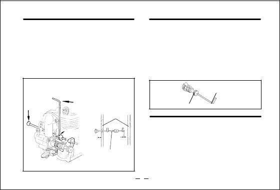
EXHAUST PIPE ADJUSTMENT(FS-26S)
The direction of the exhaust pipe may be altered in accordance with individual installation requirements. The angle is easily adjusted by loosening the nut that secures the exhaust pipe to the culinder head. Use the 10mm spanner supplied. Recheck the tightness of the nut after the engine has been run, but take care not to touch the exhaust-pipe as it becomes very hot.
9
SILENCER
The FS-26S and FS-40S are supplied with silencers as standard equipment.
Installation for FS-26S
Slide the silencer over the exhaust pipe, and secure it with two set-screwssupplied with the silencer. Recheck tightness of screws when engine is hot.
Installation for FS-40S
Screw the exhaust header pipe into the exhaust port until it "bottoms", then unscrew it just sufficiently to achieve the required exhaust outlet angle. Secure the pipe in this position by tightening the locknut firmly against the cylinder head with the wrench supplied. Then, screw the silencer onto the end of the header pipe and tighten locknut firmly. Re-check tightness of locknuts when engine is hot.
LINKAGE OF THROTTLE LEVER
First, ensure that the throttle rotor is fully closed when the throttle-lever is in the closed position. Adjust rotor stop screw if necessary. Then couple the lever to the throttle-servo so that the rotor is fully closed when the transmitter throttle stick and trim lever are in the fully retarded position.
BEFORE STARTING
Tools, accessories, etc.
The following items are necessary for operating the engine.
1 Fuel
Model glowplug engine fuel of good quality, preferably containing a small percentage of nitromethane. (See "Advice on selection of fuel, glowplug and propeller")
2 Glowplug
O.S. Type F glowplug is installed in the engine.
3 Propeller
Suggested propellers are shown in the ADVICE ON SELECTION OF FUEL & PROPELLER section.
10
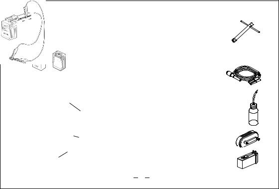
4 Glowplug battery
The power source for heating the glowplug may be either a large heavy-duty 1.5volt dry cell, or preferably, a 2-volt rechargeable lead-acid cell (accumulator).
|
If a 2-volt cell is employed, |
||
|
use a resistance wire, as |
||
|
shown, |
to reduce |
applied |
|
voltage, |
otherwise |
element |
|
will overheat and burn out. |
||
1.5 volt heavy-duty |
or 2 volt rechargeable |
|
|
dry battery |
lead-acid cell (at least 5Ah) |
|
|
Warning (Very hot)
Never touch the nichrome wire while the battery is connected.
Resistance coil |
|
|
|
to |
. |
(nichrome wire) |
|
|
voltage |
|
|
|
|
|
|
||
|
|
Lower |
brightness |
||
|
|
reduce |
|
|
|
Raise |
to |
|
|
|
|
voltage |
|
. |
|
|
|
increase |
|
|
|
||
brightness |
|
|
|
||
Battery leads
Adjust applied voltage by changing the position of clip on resistance coil until glowplug element is glowing bright red.
5 Plug wrench |
|
Used for tightening glowplug. |
|
The O.S. long plug wrench is available |
|
as an optional accessory. |
For tightening |
|
glowplug |
6 Battery leads |
|
These are used to conduct current from the battery to the glowplug. Basically, two leads, with clips, are required, but, for greater conve-
nience, twin leads with special glowplug connectors, as shown on the right, are commercially available.
7 Fuel tank
For installation in the model, a 120cc(4.2oz.) for FS-26S, a 150cc(5oz.) for FS-40S tank is
suggested.
Fuel bulb
8 Fuel bottle or pump
For filling the fuel tank, a simple, polyethylene "squeeze" bottle, with a suitable spout,is all that is required. Alternatively, one of the purpose-made manual or electric fuel pumps may be used to transfer fuel directly from your fuel container to the fuel tank.
Fuel pumps
 Manual
Electric
11
 Loading...