


FS-200S
It is of vital importance, before attempting to
operate your engine, to read the general
'SAFETY INSTRUCTIONS AND WARNINGS'
section on pages 2-4 of this booklet and to
strictly adhere to the advice contained therein.
Also, please study the entire contents of this
instruction manual, so as to familiarize
yourself with the controls and other features of
the engine.
Keep these instructions in a safe place so that
you may readily refer to them whenever
necessary.
It is suggested that any instructions supplied
with the aircraft, radio control equipment, etc.,
are accessible for checking at the same time.
1
SAFETY INSTRUCTIONS AND
WARNINGS ABOUT YOUR O.S. ENGINE
NOTES WHEN APPLYING AN
ELECTRIC STARTER
ABOUT THE ENGINE
ENGINE PARTS NAME
RELOCATION OF CARBURETOR CONTROLS
FUEL TANK & LINES
INSTALLATION
EXHAUST HEADER PIPE & SILENCER
PROPELLER
FUEL
CONTENTS
MIXTURE CONTROLS
STARTING
RUNNING-IN ("Breaking-in")
MAINTENANCE
ENGINE EXPLODED VIEW
ENGINE PARTS LIST
CARBURETOR EXPLODED VIEW
& PARTS LIST
O.S. GENUINE PARTS & ACCESSORIES
ENGINE THREE VIEW DRAWINGS
2-4
5
6
7
8
9
10-11
12
13-14
15
16
17
18
19-21
22-23
24
25
26
27
28
GLOWPLUG
2
Remember that your engine is not a " toy ", but a highly
efficient internal-combustion machine whose power is
capable of harming you, or others, if it is misused or
abused. As owner, you, alone, are responsible for the safe
operation of your engine, so act with discretion and care at
all times.
If at some future date, your O.S. engine is acquired by
another person, we would respectfully request that these
instructions are also passed on to its new owner.
WARNINGS
These cover events which might involve serious ( in
extreme circumstances, even fatal ) injury.
NOTES
These cover the many other possibilities, generally less
obvious sources of danger, but which, under certain
circumstances, may also cause damage or injury.
SAFETY INSTRUCTIONS AND
WARNINGS ABOUT YOUR
O.S. ENGINE
The advice which follows is grouped under two
headings according to the degree of damage or danger
which might arise through misuse or neglect.
WARNINGS
Never touch, or allow any object to come into
contact with, the rotating propeller and do not
crouch over the engine when it is running.
A weakened or loose propeller may disintegrate or be thrown
off and, since propeller tip speeds with powerful engines may
exceed 600 feet(180 metres) per second, it will be understood
that such a failure could result in serious injury, (see 'NOTES'
section relating to propeller safety).
Model engine fuel is poisonous. Do not allow it to
come into contact with the eyes or mouth. Always
store it in a clearly marked container and out of
the reach of children.
Model engine fuel is also highly flammable. Keep it
away from an open flame, excessive heat, sources
of sparks, or anything else which might ignite it.
Do not smoke or allow anyone else to smoke, near
to it.
Never operate your engine in an enclosed space. Model
engines, like automobile engines, exhaust deadly carbonmonoxide. Run your engine only in an open area.
Model engines generate considerable heat. Do
not touch any part of your engine until it has
coole d. Contact with the mu ffler(silencer),
cylinder head or exhaust header pipe, in
particular, may result in a serious burn.
3
NOTES
This engine was designed for model aircraft. Do not attempt to use it for any other purpose.
Mount the engine in your model securely, following the manufacturers' recommendations, using appropriate
screws and locknuts.
Be sure to use the silencer (muffler) supplied with the engine. Frequent exposure to an open exhaust may
eventually impair your hearing.
Such noise is also likely to cause annoyance to others over a wide area.
Install a top-quality propeller of the diameter and pitch specified for the engine and aircraft. Locate the propeller on
the shaft so that the curved face of the blades faces forward-i.e. in the direction of flight. Firmly tighten the propeller
nut, using the correct size wrench.
Always check the tightness of the propeller nut and retighten it, if necessary, before restarting the engine,
particularly in the case of four-stroke-cycle engines. If a safety locknut assembly is provided with your engine,
always use it. This will prevent the propeller from flying off in the event of a "backfire", even if it loosens. Also,
check the tightness of all the screws and nuts before restarting the engine.
If you install a spinner, make sure that it is a precision made product and that the slots for the propeller blades
do not cut into the blade roots and weaken them.
Discard any propeller which has become split, cracked, nicked or otherwise rendered unsafe. Never attempt to
repair such a propeller: destroy it. Do not modify a propeller in any way, unless you are highly experienced in tuning
propellers for specialized competition work such as pylon-racing.
Use an electric starter for this engine. The wearing of safety glasses is also strongly recommended.
4
Take care that the glow plug clip or battery leads do not come into contact with the propeller.
Also check the linkage to the throttle arm. A disconnected linkage could also foul the propeller.
After starting the engine, carry out any needle-valve readjustments from a safe position behind the rotating
propeller. Stop the engine before attempting to make other adjustments to the carburetor.
Adjust the throttle linkage so that the engine stops when the throttle stick and trim lever on the transmitter are fully
retarded. Alternatively, the engine may be stopped by cutting off the fuel supply. Never try to stop the engine
physically.
Take care that loose clothing (ties, shirt sleeves, scarves, etc.) do not come into contact with the propeller.
Do not carry loose objects (such as pencils, screwdrivers, etc.) in a shirt pocket from where they could fall through
the propeller arc.
Do not start your engine in an area containing loose gravel or sand. The propeller may throw such material in your
face and eyes and cause injury.
For their safety, keep all onlookers (especially small children) well back (at least 20 feet or 6 meters) when preparing
your model for flight. If you have to carry the model to the take-off point with the engine running, be especially
cautious. Keep the propeller pointed away from you and walk well clear of spectators.
Warning! Immediately after a glowplug-ignition engine has been run and is still warm, conditions sometimes exist
whereby it is just possible for the engine to abruptly restart if the propeller is casually flipped over compression
WITHOUT the glowplug battery being reconnected. Remember this if you wish to avoid the risk of a painfully rapped
knuckle!
NOTES
5
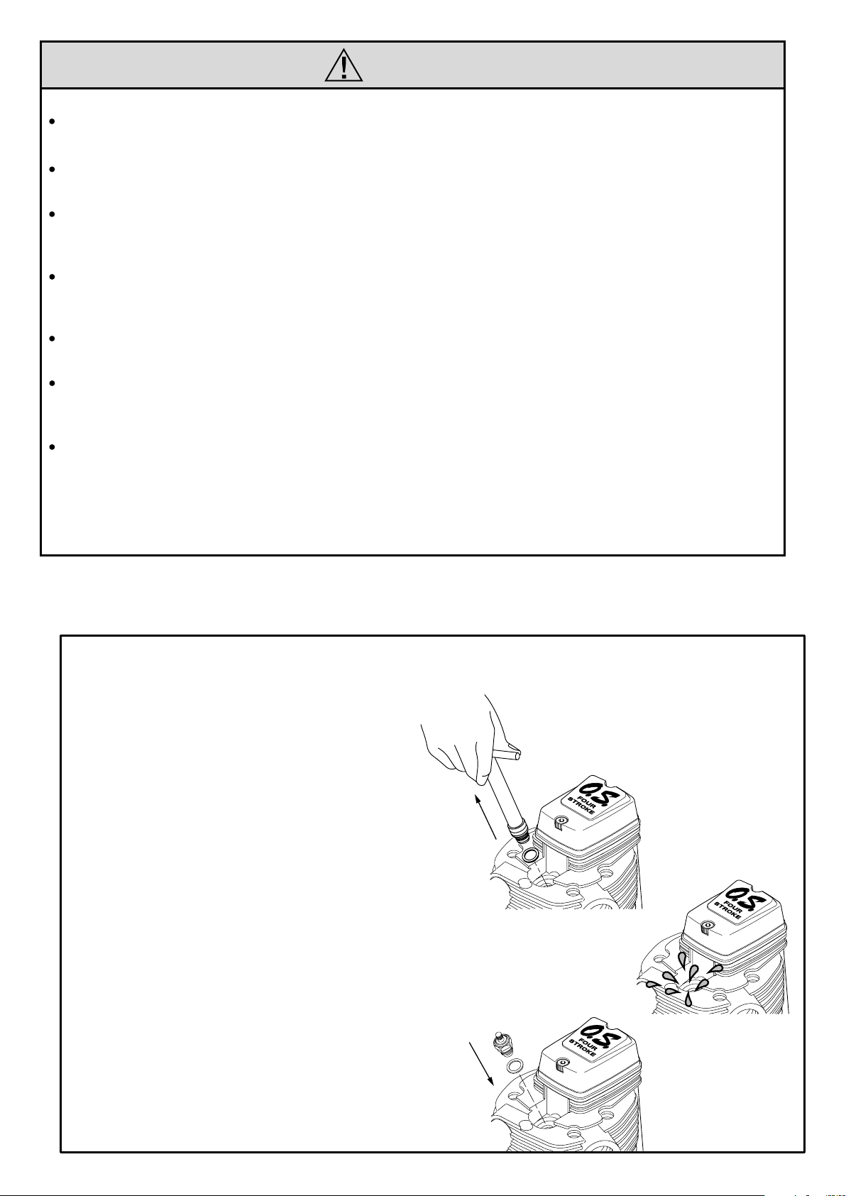
NOTES WHEN APPLYING
AN ELECTRIC STARTER
Do not over-prime. This could
cause a hydraulic lock and
damage the engine on application
of the electric starter.
If over-primed, remove glowplug,
close needle-valve and apply
starter to pump out surplus fuel.
Cover the head with a rag to
prevent pumped out fuel from
getting into your eyes.

6
ABOUT THE ENGINE
STANDARD ACCESSORIES
Needle Valve Extension Cable Set
This is an overhead valve four stroke cycle
engine for model aircraft use. This engine has
a largest displacement of 32.4cc in the FS
series and is suitable for scale and sport
models.
The engine is equipped with an easy to adjust
80N carburetor which can be reversed 180°
and supplied with a F-6010 silencer which
produces the milder four stroke sound.
F-6010 Silencer Assembly
Glowplug TypeF
7
ENGINE PARTS NAME
Rocker Cover
Glow Plug TYPE F
Lock Nut
Drive Hub
Crankcase
Beam Mount
Cover Plate
Exhaust Header Pipe
F-6010 Silencer Body
Cylinder Head
Carburetor Type 80N
Intake Manifold
Propeller Washer
Propeller Nut
Exhaust Header Pipe Nut M16
8
N.+M3x22
N.+M3x22
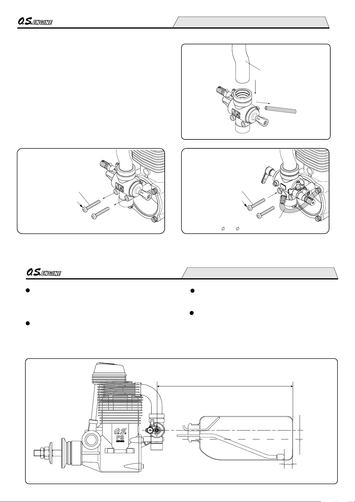
RELOCATION OF CARBURETOR CONTROLS
Carburetor Retaining Screw
Intake Manifold
Carburetor Retaining Screw
2.5x5xL85
Remove the carburetor retaining screws and remove the
silicone tube between the carburetor and cover plate.
Then, pull out the carburetor gently from the intake
manifold.
Rotate the carburetor 180°and insert on the intake
manifold straight and gently. Do not force at an angle or
the O ring inside the carburetor may be damaged.
Re-install the retaining screws. Then, connect the
carburetor and cover plate with a new silicone tube of
2.5mm inner dia and 5mm outer dia 85mm in length cut
from commercially available tubing.
Commercially available silicone tube
1.
2.
3.
Pull out the carburetor gently.
9
FUEL TANK & LINES
Make sure that the tank is well rinsed out with methanol or
glow fuel before installation and that the pickup weight is
well clear of the bottom of the tank when held vertically.
For plumbing, use heavy duty silicone tube of 2.5mm inner
dia and 5mm outer dia.
The suggested fuel tank size is 500cc or 14 oz. This will
give approximately 10 minutes running time when some
part-throttle operation is included.
Locate the fuel tank so that the center line of the tank is 10
to 15mm below the center line of the needle-valve.
Approx. 15mm
Approx.
10-15mm
needle-valve Center Line
Fuel Tank Center Line
Locate the fuel tank as close to the engine as possible
to minimize fuel level variation.
 Loading...