


Two stroke gasoline engine for airplanes
GT55
It is of vital importance, before attempting to operate your engine, to read the general
'SAFETY INSTRUCTIONS AND WARNINGS' section on pages 2-5 of this booklet and to strictly adhere to the advice contained therein.
 Also, please study the entire contents of this instruction manual, so as to familiarize yourself with the controls and other features of the engine.
 Keep these instructions in a safe place so that you may readily refer to them whenever necessary.
 It is suggested that any instructions supplied with the aircraft, radio control equipment, etc., are accessible for checking at the same time.
|
|
|
|
|
|
|
|
V |
|
|
|
|
|
|
|
|
-7.6 |
|
|
|
|
|
|
|
DC |
4.8V |
|
/4.8V |
|
|
|
|
|
|
|
|
/60 |
00r |
pm |
|
|
e |
|
60 |
0mA |
|
V |
||
oltag |
|
|
|
|
|
/4.8 |
|||
ut v |
|
|
rrent |
|
|
|
rpm |
||
Inp |
|
|
|
|
000 |
|
|||
|
|
cu |
20KV |
/6 |
|
|
|||
ption |
|
|
|
|
|||||
|
um |
|
|
|
|
|
|
|
|
Cons |
|
ge |
|
|
|
|
|
||
|
|
|
|
|
|
|
|||
|
volta |
|
|
|
|
|
|
||
put |
|
|
|
|
|
|
|
|
|
Out |
|
|
|
|
|
|
|
|
|
|
|
CONTENTS |
|
SAFETY INSTRUCTIONS AND |
|
|
18-23 |
WARNINGS ABOUT YOUR O.S. ENGINE |
2-5 |
RUNNING-IN / STARTING |
|
ABOUT THE ENGINE |
6 |
NEEDLE ADJUSTMENTS |
24-25 |
ENGINE PARTS NAME |
7 |
FLIGHT & MAINTENANCE |
26-27 |
SILENCER / INSTALLATION |
8 |
ENGINE EXPLODED VIEW |
28 |
FUEL TANK & LINES |
9 |
ENGINE PARTS LIST |
29 |
CARBURETOR WLA-2 PARTS NAME |
10 |
CARBURETOR EXPLODED VIEW |
30 |
CARBURETOR LINKAGE |
11-12 |
CARBURETOR PARTS LIST |
31 |
IGNITION MODULE |
13-14 |
O.S. GENUINE PARTS & ACCESSORIES |
32 |
PROPELLER |
15-16 |
ENGINE THREE VIEW DRAWINGS |
33 |
MIXING OF OIL |
17 |
MEMO |
34 |
1
SAFETY INSTRUCTIONS AND WARNINGS ABOUT YOUR O.S. ENGINE
Remember that your engine is not a " toy ", but a highly efficient internal-combustion machine whose power is capable of harming you, or others, if it is misused or abused. As owner, you, alone, are responsible for the safe operation of your engine, so act with discretion and care at all times.
If at some future date, your O.S. engine is acquired by another person, we would respectfully request that these instructions are also passed on to its new owner.
 The advice which follows is grouped under two headings according to the degree of damage or danger which might arise through misuse or neglect.
 WARNINGS
These cover events which might involve serious (in extreme circumstances, even fatal ) injury.
 NOTES
NOTES
These cover the many other possibilities, generally less obvious sources of danger, but which, under certain circumstances, may also cause damage or injury.
2
 WARNINGS
 Never touch, or allow any object to come into contact with the rotating propeller and do not crouch over the engine when it is running.
 Gasoline is poisonous. Do not allow it come into contact with the eyes or mouth. Always store it in a clearly marked container in a cool and dark place and out of the reach of children. There is a possibility that it may damage your health.
 Gasoline is highly flammable. Keep it away from an open flame, excessive heat, sources of sparks, or anything else which might cause it to ignite. Do not smoke or allow anyone else to smoke near to it.
 Carry out the mixing of the gasoline and oil outdoors or in a well ventilated place away from any source of fire to prevent the possibility of a fire.
 Refill the fuel tank only after the engine is well cooled down, or there is a danger of fire.
 WARNINGS
 Observe the laws and regulations in each country and district concerning the usage, transportation and storage of gasoline. Ask details at fire station in each district.
 Model engines generates considerable heat. Do not touch any part of your engine until it has cooled. Contact with the muffler (silencer), cylinder head or exhaust header pipe, in particular, may results in a serious burn.
 Never operate your engine in an enclosed space. Model engines, like automobile engines, exhaust deadly carbon-monoxide. Run your engine only in an open area.
 Do not operate the engine nor model alone, or there is a possibility of injury.
 NOTES
NOTES
 Any propeller requires utmost attention to handle. Be sure to follow the instruction manual supplied with a propeller.
 This engine was designed for model aircraft. Do not attempt to use it for any other purpose.
 Start the engine only after installing it in the model. Do not start the engine before installing it in the model, or there is a possibility of injury.
 Be sure to use an effective silencer (muffler). Frequent exposure to an open exhaust may eventually impair your hearing. Such noise is also likely to cause annoyance to others over a wide area.
 Mount the engine in your model securely, following the manufacturers’ recommendations.
 For their safety, keep all onlookers (especially small children) well back (at least 10 meters) when preparing your model for flight.
3

 NOTES
NOTES
 When checking a spark plug with the power source on, do not hold the plug, plug cap, high tension cord nor grounding wire, or you will get a shock.
 Install a top-quality propeller of the diameter and pitch specified for the engine and aircraft.
 Do not use a nylon propeller. It has the possibility of flying apart due to strong centrifugal force caused by high rpm.
 Discard any propeller which has become split, cracked, nicked or otherwise rendered unsafe. Never attempt to repair such a propeller: destroy it. Do not modify a propeller in any way.
 Install the propeller on the shaft so that the curved face of the blades faces forward – i.e. in the direction of flight. Firmly tighten the propeller washer and propeller installing screws using the correct size wrench. Always check the tightness of propeller installing screws and retighten them, if necessary, before starting the engine. Also, check the tightness of all the screws and nuts before restarting the engine.
 Always check the throttle linkage.
If it is disconnected, throttle action becomes uncontrollable, which may result in a serious accident.
 Take care that loose clothing (ties, shirt sleeves, scarves, etc.) do not come into contact with the propeller. Do not carry loose objects (such as pencils, screwdrivers, etc.) in a shirt pocket from where they could fall through the propeller arc.
 Use an electric starter for this engine. The wearing of safety glasses is also strongly recommended.
If you try hand starting, be sure to use a chicken stick or heavy glove. Never attempt to start the engine with a bare hand.
 Be sure to carry out adjustments of the high speed needle and slow speed needle after stopping the engine.
 Do not start your engine in an area containing loose gravel or sand. The propeller may throw such material in your face and eyes and cause injury.
4
 NOTES
NOTES
 If you have to carry the model to the take-off point with the engine running, be especially cautious. Keep the propeller pointed away from you and walk well clear of spectators.
 Switch off the ignition module to stop the engine or fully close the throttle valve via the transmitter to shut off the fuel supply. Otherwise there is a possibility of injury.
 Immediately after the engine is stopped, the engine may start with a crank even when the igniter switch is off. Do not crank the engine, or there is a possibility of injury.
 Be sure to install an externally operable switch for the ignition system battery to stop the engine if it is started unintentionally with the radio transmitter turned off or there is the possibility of injury.
 Connect the throttle linkage so that the engine can be stopped via radio operation.
5

ABOUT THE ENGINE
 This engine is designed for experienced fliers. Beginners and newcomers should not use this engine.
 The engine unit, carburetor and igniter are specially designed.
 It offers broad power characteristics suitable for sport flight as well as acro flight.
 The large and dense cooling fins ensure sufficient cooling against overheating.
 The specially designed ignition module “IG-01” is equipped with a micro computer and designed not to operate at low rpm and run intermittently when the battery voltage drops. It provide high voltage for sure firing through the operating range while utilizing a low current draw.
6
STANDARD ACCESSORIES
 Spark Plug CM-6
Exhaust Gasket GT55
Ignition module Assembly (IG-01)
|
|
|
|
|
|
|
|
|
V |
|
|
|
|
|
|
|
|
|
-7.6 |
|
|
|
|
|
|
|
DC |
4.8V |
|
/4.8V |
||
|
|
|
|
|
|
|
|
/60 |
00r |
pm |
|
|
|
|
|
0mA |
|
||||
|
e |
|
60 |
|
|
V |
||||
oltag |
|
|
|
|
|
|
/4.8 |
|||
ut v |
|
|
rrent |
|
|
|
|
rpm |
||
Inp |
|
|
|
|
|
000 |
|
|||
|
|
cu |
20K |
V/6 |
|
|
||||
ption |
|
|
|
|
|
|||||
|
sum |
|
|
|
|
|
|
|
|
|
Con |
|
ge |
|
|
|
|
|
|
||
|
|
volta |
|
|
|
|
|
|
|
|
tput |
|
|
|
|
|
|
|
|
|
|
Ou |
|
|
|
|
|
|
|
|
|
|
ENGINE PARTS NAME
Spark Plug |
Cylinder Head |
Velocity Stack
Carburetor Complete WLA-2
Propeller Retaining Screws
Propeller Washer
High Tension Cord |
Ground Wire |
Pilot Shaft |
|
Drive Spacer |
|
RPM Sensor |
|
Crankcase
Sensor Leads
Cover Plate
|
|
|
|
|
|
|
-7.6V |
V |
|
|
|
|
|
DC |
4.8V |
||
|
|
|
|
|
|
|
/4.8 |
|
|
|
|
|
|
|
|
rpm |
|
|
|
|
|
|
|
000 |
|
|
|
age |
|
600m |
A/6 |
.8V |
|||
|
|
|
|
|||||
|
volt |
|
ent |
|
|
0rp |
m/4 |
|
put |
|
|
|
|
|
|
||
In |
|
on |
curr |
|
|
/600 |
|
|
|
|
KV |
|
|||||
|
pti |
|
20 |
|
|
|
||
nsum |
|
|
|
|
|
|
||
Co |
|
ge |
|
|
|
|
||
|
|
volta |
|
|
|
|
|
|
tput |
|
|
|
|
|
|
|
|
Ou |
|
|
|
|
|
|
|
|
Sensor Leads
Battery Leads
7
SILENCER / INSTALLATION
Be sure to use an effective silencer (muffler). Frequent exposure to an open exhaust may eventually impair your hearing. Such noise is also likely to cause annoyance to others over a wide area.
The GT55 does not come with a silencer. Select an effective silencer from commercially available ones. (Mounting bolt pattern is the same as most other makes of the similar engine size.)
Mount the engine in your model securely, following the manufacturers’ recommendations.
Use a strong enough material for the mounting face of the model, such as birch ply firewall of more than 8mm thick.
Make sure the mounting face of the model is flat. If it is uneven, work on it to be flat. (When shims are added to change the thrust angle, work on it to be flat.)
Engine mounting face has been high-precision machined flat. Make sure mounting face of the model is also flat.
Use 5mm steel hex socket head bolts to install the engine. (Do not use brass, soft steel nor aluminum screws, because they are not strong enough.)
Also, use the Nord Lock Washers (optional extra) and other anti-loosening washers or apply locking agent.
Be sure that there is sufficient air intake and outlet area on the model for engine cooling to avoid overheating.
(Pay careful attention to the cooling since a gasoline engine generates more heat than a glow engine.)
Secure at least a 30mm dia. area around the air intake of the velocity stack so that the air intake will not be restricted. (Cut out the cowling big enough if necessary.)
8
|
FUEL TANK & LINES |
Use a tank designed for gasoline. |
Use fuel line keepers at the end of the tubing to prevent at |
(Tanks designed for glow fuel use a rubber cap which is |
from coming off. |
deteriorated by gasoline.) |
|
|
This engine does not require a muffler pressurized fuel |
A 600cc tank will provide 13~14 minutes flight. |
system but be sure to provide an air vent. |
Install a commercially available gasoline fuel filter between |
Be sure to install an in-line fuel filter between the tank and |
fuel tank and carburetor. (Clean the filter from time to time.) |
carburetor to prevent foreign matter in the tank from |
|
entering the carburetor. Clean the filter periodically. |
For plumbing use TYGON R F-4040 (Yellow color) or strong |
|
nitrile rubber of more than 3mm ID and 6mm OD. |
|
Replace tubing periodically as it becomes hardened. |
|
(Replace tubing inside the fuel tank every six months.) |
|
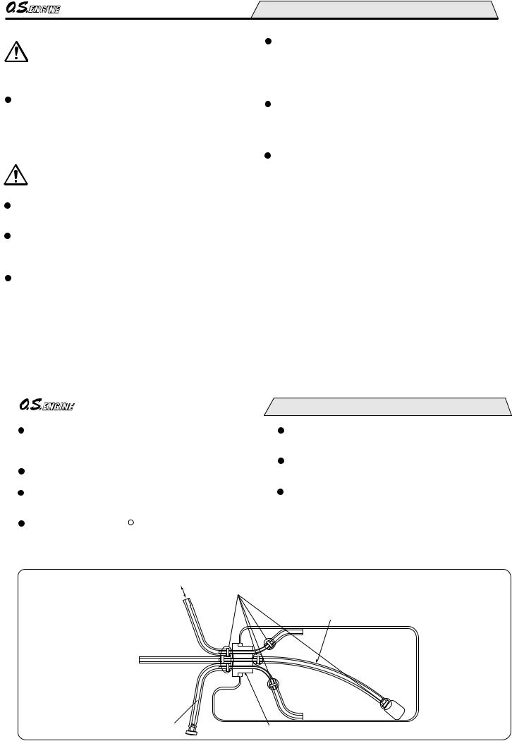
Be sure to equip air vent pipe.
Be sure to use binding band to prevent from coming off.
Be sure to replace piping inside periodically.
To carburetor fuel inlet 
Piping for re-fuelling
Be sure to use a gasoline resistant fuel tank cap.
9
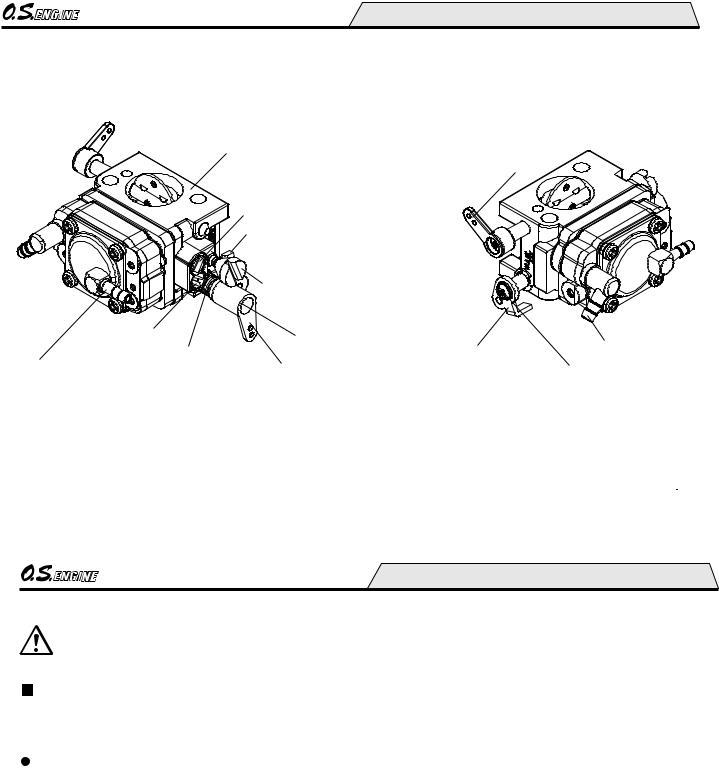
CARBURETOR WLA-2 PARTS NAME
Carburetor Body
|
|
Choke Valve Lever |
|
High Speed Needle |
|
|
|
|
Idle Speed Stop Lever |
|
|
|
Idle Speed Stop Screw |
|
|
|
(No need to adjust. Factory adjusted.) |
|
|
Slow Speed Needle |
Throttle Valve Lever |
|
|
Spring Throttle Return |
Retaining Screw |
High Speed Stop Lever |
Fuel Inlet |
Air Vent Fitting |
Throttle Valve Lever |
High Speed |
|
(No need to connect in normal use.) |
|
Stop Lever Retaining Screw |
|
10
CARBURETOR LINKAGE
Connect the throttle linkage so that the engine can be stopped via radio operation.
Connect the throttle linkage so that the engine can be stopped by radio operation in case of unexpected starting, or there is a possibility of injury.
Throttle lever can be installed either on right or left. Here is a changing procedure.
1.Remove the throttle lever retaining screw. (Pay attention not to lose this screw because it is special size.) Also, be careful not to remove the idle stop screw and return spring. If they are removed accidentally, assemble them being aware of the small notch.
2.Then, remove the opposite side high speed stop retaining screw. (Pay attention not to lose this screw because it is special size.) At this time, be careful not to remove the high speed stop lever.
3.Then, install the throttle lever with the throttle lever retaining screw.
NOTE
When loosening and tightening each retaining screw, do so with the throttle valve at mid position.
(If the throttle valve lever retaining screw is loosened or tightened with the throttle valve fully opened or closed, excessive force will be applied, which will results in breaking the lever.)
4.Then, install the idle speed stop lever with the high speed stop lever retaining screw.
11
 Loading...