

Two stroke glow gasoline
600930400000
It is of vital importance, before attempting to operate your
engine, to read the general 'SAFETY INSTRUCTIONS
AND WARNINGS' in the following section and to strictly
adhere to the advice contained therein.
Also, please study the entire contents of this
instruction manual, so as to familiarize yourself with
the controls and other features of the engine.
engine for airplanes
SAFETY INSTRUCTIONS AND WARNINGS ABOUT YOUR O.S. ENGINE
Remember that your engine is not a " toy ", but a
highly efficient internal-combustion machine
whose power is capable of harming you or others,
if it is misused or abused. As owner, you, alone,
are responsible for the safe operation of your
engine, so act with discretion and care at all times.
If at some future date, your O.S. engine is acquired
by another person, we would respectfully request
that these instructions are also passed on to its
new owner.
The advice which follows is grouped under two
headings according to the degree of damage or
danger which might arise through misuse or
neglect.
WARNINGS
These cover events which might involve serious
(in extreme circumstances, even fatal) injury.
NOTES
These cover the many other possibilities, generally
less obvious sources of danger, but which, under
certain circumstances, may also cause damage or
injury.
WARNINGS
Never touch, or allow any object to come
into contact with the rotating propeller and
do not crouch over the engine when it is
running.
Gasoline is poisonous. Do not allow it
come into contact with the eyes or mouth.
Always store it in a clearly marked
container in a cool and dark place and out
of the reach of children. There is a
possibility that it may damage your health.
Gasoline is highly flammable. Keep it away
from an open flame, excessive heat,
sources of sparks, or anything else which
might cause it to ignite. Do not smoke or
allow anyone else to smoke near to it.
ABOUT THE ENGINE
How to adjusting the carburetor of this engine is
completely different from that for the conventional glow
engine’s carburetor. Please study the CARBURETOR
ADJUSTMENT section so as to familiarize yourself
with the controls and other features.
GGT15 is a glow gasoline engine ignited by a glow
plug but using gasoline. So no ignition module and
battery is required.
This engine is designed for experienced fliers.
Beginners and newcomers should not use this engine.
The engine unit, silencer and carburetor are
specially designed.
The normal rotation direction of the engine is
counterclockwise facing to the propeller.
It offers broad power characteristics suitable for
sport flight as well as acro flight.
The large and dense cooling fins ensure sufficient
cooling against overheating.
We apply a “G5” glow plug to GGT15, which is
exclusively developed for Glow Gasoline engines.
Buy only the same glow plug when you replace it to
the new one due to a break or deterioration. The
conventional glow plugs for alcohol based glow
engines such as No.6 (A3), No.7, No.8, No.10 (A5)
are not applicable to GGT15.
The supplied E-4040 silencer develops very efficient
silencing.
STANDARD ACCESSORIES
E-4040 Silencer Assembly
Silencer Retaining Screw
(M4x40 2pcs.)
GGT15
Carry out the mixing of the gasoline and
oil outdoors or in a well ventilated place
away from any source of fire to prevent the
possibility of a fire.
Refill the fuel tank only after the engine is
well cooled down, or there is a danger of
fire.
Go outside and stay away from the
vaporized gasoline when you check the
power distribution of the glow plug attached
to the glow plug igniter by looking at the
filament. Failing to do so may cause fire.
Model engines generate considerable heat.
Do not touch any part of your engine until
it has cooled. Contact with the muffler
(silencer), cylinder head or exhaust header
pipe, in particular, may results in a serious
burn.
Observe the laws and regulations in each
country and district concerning the usage,
transportation and storage of gasoline. Ask
details at the fire station in each district.
Never operate your engine in an enclosed space.
Model engines, like automobile engines, exhaust
deadly carbon-monoxide. Run your engine only
in an open area.
Do not operate the engine nor model alone, or
there is a possibility of injury.
NOTES
Any propeller requires utmost attention to handle.
Be sure to follow the instruction manual supplied with
a propeller.
This engine was designed for model aircraft.
Do not attempt to use it for any other purpose.
Start the engine only after installing it in the model.
Do not start the engine before installing it in the
model, or there is a possibility of injury.
Be sure to use an effective silencer (muffler).
Frequent exposure to an open exhaust may
eventually impair your hearing. Such noise is also
likely to cause annoyance to others over a wide area.
Mount the engine in your model securely, following
the manufacturers’ recommendations.
For their safety, keep all onlookers (especially small
children) well back (at least 10 meters) when
preparing your model for flight.
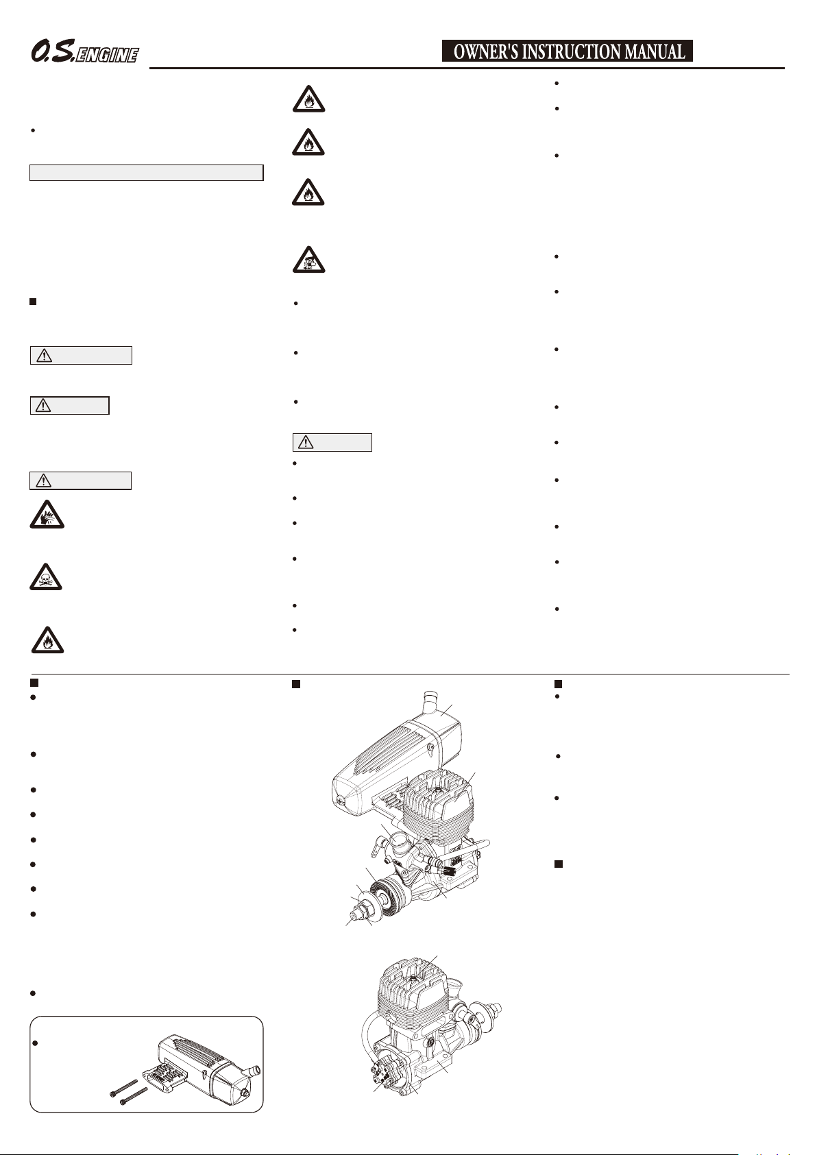
ENGINE PARTS NAME
E-4040 Silencer
Cylinder Head
Carburetor
Type 61H
Drive Hub
Propeller Washer
Propeller Nut
Crankshaft
Pump Unit PD-08
Lock Nut
Crankcase
Glow Gasoline
Plug G5
Beam Mount
Cover Plate
Install a top-quality propeller of the diameter and
pitch specified for the engine and aircraft.
Discard any propeller which has become split,
cracked, nicked or otherwise rendered unsafe.
Never attempt to repair such a propeller: destroy it.
Do not modify a propeller in any way.
Install the propeller on the shaft so that the curved
face of the blades faces forward – i.e. in the direction
of flight. Firmly tighten the propeller washer and
propeller installing screws using the correct size
wrench. Always check the tightness of propeller
installing screws and retighten them, if necessary,
before starting the engine. Also, check the tightness
of all the screws and nuts before restarting the
engine.
Always check the throttle linkage.If it is disconnected,
throttle action becomes uncontrollable, which may
result in a serious accident.
Take care that loose clothing (ties, shirt sleeves,
scarves, etc.) do not come into contact with the
propeller. Do not carry loose objects (such as
pencils, screwdrivers, etc.) in a shirt pocket from
where they could fall through the propeller arc.
Use an electric starter for this engine. The wearing of
safety glasses is also strongly recommended.
If you try hand starting, be sure to use a chicken stick
or heavy glove. Never attempt to start the engine
with a bare hand.
Be sure to carry out adjustments of the high speed
needle and slow speed needle after stopping the
engine.
Do not start your engine in an area containing loose
gravel or sand. The propeller may throw such
material in your face and eyes and cause injury.
If you have to carry the model to the take-off point
with the engine running, be especially cautious.
Keep the propeller pointed away from you and walk
well clear of spectators.
To stop the engine, fully close the throttle valve via
the transmitter to shut off the fuel supply. Otherwise
there is a possibility of injury.
Do not crank the engine right after the engine is
stopped because the engine may start with a crank
even when the glow plug is not ignited. Failing to do
so may cause injury.
Connect the throttle linkage so that the engine can
be stopped via radio operation.
INSTALLATION
It is suggested to use an engine mount as heavy and
rigid as possible for highest performance and safe
running. Install the engine on a mount using at least
3mm steel screws, such as Allen type, with locknuts,
for bolting the engine to the bearers.
Also, use the Nord Lock Washers (optional extra)
and other anti-loosening washers or apply locking
agent.
Be sure that there is sufficient air intake and outlet
area on the model for engine cooling to avoid
overheating. (Pay careful attention to the cooling
since a gasoline engine generates more heat than an
alcohol based glow engine.)
INSTALLATION OF SILENCER
Secure the silencer to the engine by means of two
retaining screws supplied after the engine is securely
mounted on a model.
The exhaust outlet of the silencer can be rotated by 90
degrees in the following manner.
Loosen the locknut of the silencer and assembly screw.
1.
Set the exhaust outlet at the required position by
2.
rotating the rear part of the silencer.
Re-tighten the assembly screw, followed by the locknut.
3.
It is recommended to seal the fitting faces of engine
exhaust and silencer with liquid gasket. Gasket at the
joint part of the silencer will lose its sealing effect in a
long time running. In this case, replace the gasket or
apply liquid gasket to the joint.
FUEL TANK & LINES
Use a tank designed for gasoline. (Tanks designed
for glow fuel use a rubber cap which is deteriorated
by gasoline.)
A 200cc tank will provide 12 to 13 minutes flight.(With
full throttle, it will provide 8 to 10 minutes flight.)
Install a commercially available gasoline fuel filter
between fuel tank and carburetor. (Clean the filter
from time to time.)
For plumbing use TYGON F-4040 (Yellow color) or
strong nitrile rubber of more than 2.4-3.2mm ID and
4.8-6.4mm OD. Replace tubing periodically as it
becomes hardened. (Replace tubing inside the fuel
tank every six months.)
For the plumbing in the fuel tank, we recommend
using O.S. fluororubber tube 2 mm ID x 4 mm OD x
500 mm length (code # 28382100).
Use fuel line keepers of stainless wire, etc. at the end
of the tubing to prevent the tubing from coming off.
This engine does not require a muffler pressurized
fuel system but be sure to provide an air vent.
Be sure to install an in-line fuel filter between the
tank and carburetor to prevent foreign matter in the
tank from entering the carburetor. Clean the filter
periodically.
Be sure to equip
air vent pipe.
To the fuel
pump inlet
tubing for
re-fuelling
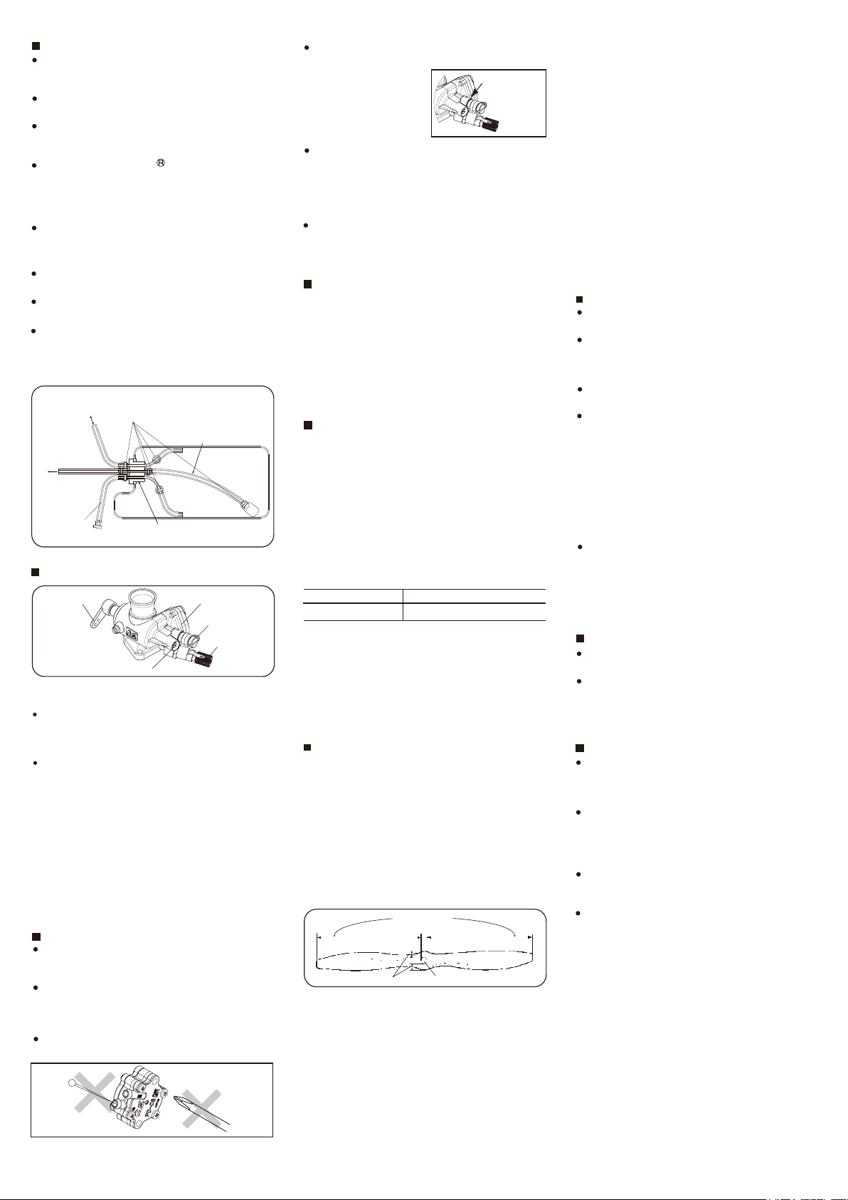
CARBURETOR PARTS NAME
Throttle Lever
Mixture Control Valve
Two adjustable controls are provided on this
carburetor.
The Needle-Valve
For adjusting the mixture strength when the throttle is
fully open Needle-valve adjustment effect the mixture
strength at round mid speed.
The Mixture Control Valve
For adjusting the mixture strength at part-throttle and
idle speed, to obtain steady idling and smooth
acceleration to mid speed.
Please note with this carburetor, needle-valve
adjustment does not effect the mixture control valve
adjustment but the mixture control valve adjustment
effects the needle-valve adjustment. Therefore, it is
required to adjust also the needle-valve when the
mixture control valve is adjusted. Mixture control valve
is pre-set at the near-best position when the engine
leaves the factory. Therefore, it is not necessary to
adjust the mixture control valve until running-in is
completed.
CARE OF FUEL PUMP & REGULATOR
NEVER disassemble the fuel pump or pressure
regulator. Their original performance may not be
restored after reassembly.
DO NOT allow foreign matter to enter the fuel
system. Dirt inside the pump or regulator, no matter
how small, may obstruct the flow of fuel and prevent
these components from working properly.
NEVER insert anything into the inlet or outlet nipples
in an attempt to clear a suspected obstruction.
Be sure to use fuel line keepers of
stainless wire, etc. to prevent tubing
from coming off.
Be sure to replace tubing
inside periodically.
Be sure to use a gasoline
resistant fuel tank cap.
Regulator
Fuel Inlet
Needle Valve
DO NOT obstruct the small rectangular hole at the
bottom of the regulator, nor the regulator will not
function correctly.
ALWAYS use fuel filters. Keep the fuel tank
scrupulously clean and filter all fuel as it enters the
tank (e.g.via an O.S.'Super-Filter' Code No.72403050)
and use a good quality in-line filter between the tank
and pump. Remember to inspect filter screens at
regular intervals and rinse clean as necessary.
NEVER use kerosene, thinner or any organic solvent
for cleansing the pump. Rubber parts will be ruined
by these materials. Use only alcohol (methanol) or
gasoline.
THROTTLE LINKAGE
Before connecting the throttle to its servo, make sure
that the throttle arm and linkage safely clear any
adjacent part of the airframe structure, etc., as the
throttle is opened and closed. Connect the linkage so
that the throttle is fully closed when the transmitter
throttle stick and its trim lever are at their lowest
settings and fully open when the throttle stick is in its
fully-open position. Carefully align the appropriate holes
in the throttle arm and servo horn so that they move
symmetrically and smoothly through their full travel.
PROPELLER
The choice of propeller depends on the design and
weight of the aircraft and on the type of flying in which you
will be engaged. Determine the best size and type after
practical experimentation. As s starting point, refer to the
props listed in the table shown below. Slightly larger, or
even slightly smaller props than those shown in the table
may be used, but remember that propeller noise will
increase if blade tip velocity is raised due to high rpm or if
a larger diameter/lower pitch prop is used. Be well aware
that the propeller rotating arc will increase when using a
larger propeller with this engine. Carry out the needle
adjustments only after stopping the engine. Do not allow
your face or hands to come close to the rotating prop.
Type
Sport/Acro/Scale
Warning:
Make sure that the propeller is well balanced.
An unbalanced propeller and/or spinner can cause
serious vibration which may weaken parts of the
airframe or affect the safety of the radio-control
system. Do not use any propeller which has
become split, cracked or nicked even very slightly,
or received strong impact even if no apparent
damage is visible.
PROPELLER & SPINNER ATTACHMENT
There is a risk, particularly with powerful two-stroke engines,
of the propeller flying off if the prop nut loosens due to
detonation ("knocking") in the combustion chamber when
the engine is operated too lean, or under an excessively
heavy load.
Obviously, this can be very hazardous. To eliminate
such dangers, the O.S. Safety Locknut Assembly was
devised.
Install this as follows:
Ream the propeller shaft hole to 8.1mm bore with
1.
an appropriate reamer, checking that the hole is
exactly centered.
To be equal
Install the prop to the engine shaft, followed by the
2.
retaining washer and prop nut and tighten firmly
with a 14mm wrench. (not supplied).
Add the special tapered and slotted locknut and
3.
secure with a 12mm wrench while holding the prop
nut with the 14mm wrench. (not supplied).
Note:
Some spinners which are retained at the top of the
cone cannot be used with the prop locknut
supplied with the engine. In this case, optional
locknut sets are available from O.S. – Propeller
Locknut Set for Spinner (Code No.45910200 4mm)
and (Code No.45910300 5mm).
13x8-11 14x8-10 15x6-8
To be equal
Ream to 8.1mm dia.
Rectangular
hole
Size (DxP)
NOTE:
Make a habit of always checking the tightness of the
propeller before starting the engine. Remember that,
especially with wooden propellers, there is a
tendency for the material to shrink, or for it to be
reduced by the serrated face of the drive hub.
Retighten the propeller nut if necessary after
loosening the Safety Propeller Locknut. The locknut
should be tightened firmly after retightening the
propeller nut.
Since the GGT15 is intended to be started with an
electric starter, the addition of a spinner assembly for
centering the starter sleeve is desirable.
Special propeller locknut sets are available for use
with spinners. Use a good quality well balanced
spinner, enclosing the propeller boss.
Make sure that it is of precision-made and sturdy
construction so that the spinner shell cannot loosen
when the starter is used.
Make sure the spinner notches do not interfere the
propeller. If they do, cut the notches to clear.
MIXING OF OIL
Use regular gasoline. (No need to use high octane
gasoline.)
Alcohol based glow fuel cannot be used in this
engine. Not only will the engine not work properly
but the internal carburetor plastic parts will be
damaged.
Use high quality commercially available 2 stroke
engine oil.
Follow the oil manufacturer’s recommendations
concerning the mixture ratio of gasoline and oil.
If there is no recommendation, mix with a 25~30:1.
We have checked the following oils with the
mixture of 50:1.
KLOTZ ModeLube®
AMSOIL Saber
Zenoah Genuine FC Class
Concerning the mixture ratio for running-in,
follow the instructions in the RUNNING-IN
section.
With a gasoline engine, passages in the carburetor
are narrower than that of a glow engine, and
therefore very sensitive against foreign matter such
as dust. It is suggested to use optional accessory
Super Filter L (Code No. 72403050) when filling a
tank in the model from a container used for
transportation or storing.
GLOWPLUG IGNITER
A glow plug heater for GGT15 is nothing special.
You can use a conventional glow plug igniter.
You may find the G5 glow plug filament does not
glow as bright as the conventional glow plugs.
But you can start the engine without difficulties since
the flashpoint of gasoline is lower than that of
alcohol based glow fuel.
RUNNING-IN
Use a fuel with increased oil content and set the
needle a little on the rich side. Too rich a needle
setting may cause misfiring or erratic running due to
fouling of the plug.
Use a 25:1 fuel/oil mixture if the particular brand of
oil states 50:1 mix. Use a 20:1 fuel/oil mixture if the
particular brand of oil states 25:1 mix.
Set only the high speed needle 200 below maximum
rpm. The low speed needle need not be richened.
No need to carry out running-in on a bench nor with
the model fixed. Just fly the model with the above
mentioned fuel and needle setting.
A total of 10 flights (2 litters fuel) are required.
Avoid prolonged full throttle running at initial stage,
and gradually extend the full throttle running time.
WARNING:
When ground running the engine, avoid dusty or
sandy locations. If dust or grit is drawn into the
engine, this can have a ruinous effect, drastically
shortening engine life in a matter of minutes.

STARTING
The GGT15 cannot be started by flipping a propeller.
Be use to use an electric starter to start the engine.
The GGT15 is not equipped with a choke valve.
Draw the fuel to the carburetor by an electric starter.
1.
Open the needle-valve 2.5 to 3 turns from the fully
closed position. (Mixture control valve is pre-set at
nearly best position when the engine leaves the
factory.Therefore, do not adjust the mixture control
valve at this point.)
Set the throttle at 1/3 open from the fully closed
2.
position.
Tell the helper and onlookers that you will start the
3.
engine now and have the helper hold the model
securely.
Connect a glow plug igniter or battery leads to the
4.
glow plug.
Apply an electric starter to start the engine.
5.
NOTE:
It may be difficult to start the engine when air
temperature is below 10 degrees Celsius. In this
case, keep running the electric starter for around
10 seconds even the engine starts firing.
CARBURETOR ADJUSTMENT
1.
Before attempting to operate your engine
Although the carburetor’s appearance and construction
resemble conventional glow engine’s carburetor, how
to adjusting is completely different from that for glow
engine‘s carburetor. Please study the following
instructions so as to familiarize yourself with the
controls and other features of the engine.
It is expected the engine runs a little unstably
(uneven RPM and light breathing) until the inside
parts of the carburetor get used to the fuel (around
when the running-in is completed) but the engine
won’t quit. Run the engine as it is. Also, for about 10
seconds after the first starting of the day, it is
expected the engine runs unstably but the engine
won’t quit. Run the engine as it is.
2.
Key points for adjustments
Mixture control valve is pre-set at the near-best
1)
position when the engine leaves the factory.
Therefore, it is not necessary to adjust the mixture
control valve until running-in is completed.
Adjust the needle-valve only.
With a conventional glow engine, the needle-valve
2)
is gradually closed from the rich mixture. On the
contrary, with the GGT15, the needle-valve is
opened from the lean mixture. Please fully note
this difference.
3.
Adjustments
1) Needle-valve adjustment
Gradually open the throttle fully when the engine is
1.
started.
Close the needle-valve and the engine RPM
2.
increase. (Close the needle-valve at a pace of
30~45 degrees/second smoothly.)
When the needle-valve is closed further, engine
3.
RPM stop increasing and then RPM start decreasing.
Close the needle-valve 60 to 90 degrees further from
the point where RPM start decreasing.
Then, open the needle-valve rather slowly (at a
4.
pace of 15 degrees/second) and the engine RPM
increase.
Open the needle-valve 90 degrees further from the
5.
point where maximum RPM are obtained. This is
the nearly best needle-valve position.
Fly the model with this needle-valve position until
running-in is completed (10 full tank or 2 liters flights).
Please observe the general precautions during
running-in such as to avoid prolonged full throttle
running and increase load gradually.
2) Adjustment after running-in
Open the mixture control valve 60 degrees from
1.
the original position (factory setting).
Start the engine.
2.
Open the throttle fully 10 seconds to warm the
3.
engine up.
4.
Close the throttle fully.
Set the idling RPM at round 3,000 with the throttle
5.
trim on the transmitter.
6.
Stop the engine.
Close the mixture control valve 15 degrees.
7.
Start the engine and write down the idling RPM.
8.
9.
Repeat 6 to 8. 9. The position where 90 degrees
opened position from maximum idling RMP is
obtained is the optimum mixture control valve
position. Warning! Never adjust the mixture control
valve while running the engine.
10.
Readjust the needle-valve according to 3. (1)
described above.
11.
Now the adjustment on the ground is completed.
Hereafter adjust the needle-valve and/or mixture control
valve if required according to the flight conditions.
Please note with this carburetor, needle-valve adjustment
does not effect the mixture control valve adjustment but
the mixture control valve adjustment effects the
needle-valve adjustment.
Therefore, it is required to adjust also the needle-valve
when the mixture control valve is adjusted.
3) Initial mixture control valve position
While the mixture control valve is set at the near-best
position when the engine leaves the factory, it is
possible you lost the initial position in repeating the
mixture control valve adjustment.
How to reset the initial mixture control valve position is
as follows. Please note this work is very sensitive.
Carry out the work very carefully.
Open the mixture control valve one turn (360
1.
degrees).
Repeat opening the throttle fully and closing the
2.
throttle fully a few times to make sure there is no
resistance during throttle movement.
Close the mixture control valve 30 degrees.
3.
Repeat 2. and 3. until resistance is felt when
4.
opening the throttle from fully closed position.
Open the mixture control valve approx. 90 degrees
5.
from this point. This is the initial mixture control
valve position.
Note
Generally, a gasoline engine is sensitive to a lean
mixture compared with an alcohol based glow
engine, and will stop without warning hesitation
and stops with overheating.
It is recommended that the engine be run with a
slightly richer mixture.
FLIGHT & MAINTENANCE
Checking prior to flight
When the engine is started, make sure the radio
control system works normally (distance test).
Engine does not run erratic with full throttle.
Idling is stable.
Responds positively to the throttle operation.
Warm-up is finished.
Warm-up is required as with full size aircraft and car
engines. Take off with the model after warming the
engine for approx. 10 seconds with full throttle.
Precautions in flight
A slight engine rpm increase and decrease delay is
normal. Abrupt throttle operation will cause the
engine to quit. Move throttle smoothly.
Cooling is more vitally important to a gasoline engine
than to an alcohol based glow engine. If overheating
symptoms (loss of power at full throttle or exhaust
note at mid speed changes from cloudy one to clear
one) are observed during flight, immediately stop
flying and carry out the following countermeasures.
)
Enlarge the air intake cutout on the cowling.
1
Enlarge the air outlet cutout on the cowling. (It is
2)
vitally important.)
Partly cover the air intake cutout on the cowling
)
3
where air does not hit direct the engine.
Install an air guiding plate on the fuselage and
4)
cowling so that cooling air may be guided to the
cylinder portion of the engine and muffler.
When the interval between the flights is short and
the engine is still hot, it may be possible overheating
symptoms are observed by circulating the head from
the former flight through the engine even if the
overheating symptoms were not observed during
the former flight. In this case, leave it until the
engine is fully cooled down (in hot weather, it may
take more than one hour.) or run the engine for 4 to
5 minutes at idle.
Maintenance after the day’s flights
Please pay attention to the matter described below
to ensure that your engine serves you well in
regard to performance, reliability and long life.
Check the tightening of each screw, especially
engine installation screws and silencer installation
screws each time. Also, for the first several flights,
tighten the screws after each flight.
As previously mentioned, it is vitally important to
avoid operating the engine in conditions where dust,
distributed by the propeller, may be deposited on the
engine and enter its working parts.
Remember to keep your fuel container closed to
prevent foreign matter from contaminating the fuel.
Install a fuel filter to prevent foreign matter in the fuel
container from entering the fuel tank. O.S. Super
Filter (L) is available as an optional extra.
Install an in-line fuel filter between the tank and
carburetor to prevent foreign matter in the tank from
entering the carburetor.
Clean these filters periodically.
If these precautions are neglected, restrictions of
fuel flow may cause the engine to cut out, or the
fuel/air mixture to become too lean causing the
engine to overheat.
With a gasoline engine rust hardly occurs. Check
the exterior to make sure there is nothing wrong and
wipe off any oil res.
Fill the carburetor with fuel at the conclusion of a
day's flying. (Pay careful attention to fire and ignition
source when carrying and storing the model.)
If the engine is stored without filling the carburetor
with fuel the inside parts will dry out and not work
properly at the next running. If the engine quits out
of fuel, refill the carburetor with fuel.
When the engine is not to be used for a long period
(more than a year), remove the engine from the
model, clean the outside then remove the
carburetor, and plug all tubing. Clean inside the
engine by rotating the crankshaft with the engine
immersed in container filled with gasoline.
Also use gasoline to clean the outside of the
carburetor. Clean the outside only because the
inside parts are sensitive to foreign substances.
After cleaning the engine, dry it well then inject a
small quantity of oil used to mix fuel and rotate the
crankshaft several times to distribute the oil well
inside the engine. Finally reassemble the engine
and store it in a dry place after inserting it in a heavy
vinyl bag.
O.S. GENUINE PARTS & ACCESSORIES
(27426010)
(79870040)
M4
(71655001)
)
)
GLOW GASOLINE ENGINE PLUG G5
E-4051 SILENCER ASSEMBLY
PROPELLER LOCKNUT
SET FOR SPINNER
5/16"-M4
5/16"-M5
(45910200)
(45910300)
NON-BUBBLE WEIGHT
(S)
(71531010)
SUPER FILTER (S
(72403051)
SUPER FILTER (L
(72403050)
BLIND NUT (10pcs.)
LOCK WASHER (10sets)
(55500003)
M4
FLUORORUBBER TUBE
(
ID. 2mm × OD. 4mm Length 500mm
ID. 3mm × OD. 5mm Length 500mm
The specifications are subject to alteration for improvement
without notice.
28382100
(
28382200
)
)

ENGINE EXPLODED VIEW
Type of screw
C...Cap Screw N...Round Head Screw
C.M3x15
2
9
C.M3x15
10
12
11
14
13
Code No.
1
24-2
24-4
24-3
24-1
24
2-1
3
21
4
5
7
6
20
8
17
22
C.M3x12
N.+M3x18
23-1
23
19
18
16
15
CAP SCREW SETS
Code No.
79871140
79871150
Size
M3x12
M3x15
(10pcs./sets)
Pcs. used in an engine
Cover Plate Retaining Screw (4pcs.)
Cylinder Head Retaining Screw (6pcs.)
Caburetor Retaining Screw (2pcs.)
No.
71655001
1
4A204000
2
29061406
2-1
29503100
3
28153400
4
28163200
5
26606008
6
28117010
7
28155000
8
28181010
9
28169460
10
45910100
11
29008219
12
29508000
13
46120000
14
26731002
15
4A201000
16
28151300
17
29030001
18
28162000
19
28152100
20
29514000
21
28167000
22
72508100
23
29067130
23-1
27425011
24
29122540
24-1
27425300
24-2
26625210
24-3
23081706
24-4
The specifications are subject to alteration for improvement without notice.
Glow Gasoline Engine Plug G5
Cylinder Head
Head Gasket
Cylinder Liner
Piston Ring
Piston
Piston Pin
Piston Pin Retainer (2pcs.)
Connecting Rod
Carburetor Complete (Type 61H)
Thermo Insulator
Lock Nut Set
Woodruff Key
Drive Hub
Thrust Washer
Ball Bearing (F)
Crankcase
Crankcase Plug
Ball Bearing (R)
Crankshaft
Crank Pin Stop Screw
Gasket Set
Cover Plate
Pump Unit PD-08
Pan Head Screw (N.+M3x18 10pcs.)
E-4040 Silencer
"O" Ring
Assembly Screw
Silencer Retaining Screw (C.M4x40 2pcs.)
Carburetor Retaining Screw (N.+M3.5x5 2pcs.)
Description
CARBURETOR EXPLODED VIEW & PARTS LIST
N.+M3x6
C.M3x15
1-1
1
2
THREE VIEW DRAWING
Dimensions (mm)
Specifications
Displacement
Bore
Stroke
PracticalR.P.M.
Output
Weight
14.95 cc / 0.912 cu.in.
27.7 mm / 1.091 in.
24.8 mm / 0.976 in.
2,000-11,000 r.p.m.
2.35 ps / 2.32 hp / 15,000r.p.m.
610 g / 21.52 oz.
178 g / 6.28 oz.
(Engine)
(Silencer)
3
3-1
Code No.
Type of screw
N...Round Head Screw S...Set Screw
4
3-2
6
S.M3X3
5
7-2
7-1
54.3
4°
103.3
7-4
7-5
7-3
7
24.3
No.
1
27881400
1-1
22081313
2
28181210
3
28181600
3-1
28181920
3-2
28181910
4
28181110
5
45581820
6
45571110
7
28181900
7-1
28181970
7-2
26381501
7-3
28181910
7-4
27381940
7-5
26711305
The specifications are subject to alteration for improvement without notice.
25
40.3
30°
12.5
12.5
10
6.5
42
Throttle Lever Assembly
Throttle Lever Retaining Screw
Carburetor Rotor
Mixture Control Valve Assembly
"O" Ring (L) (2pcs.)
"O" Ring (S) (2pcs.)
Carburetor Body
Roter Guide Screw
Universal Nipple L3.5
Needle Valve Assembly
Needle Assembly
Set Screw
"O" Ring (2pcs.)
Needle-valve Holder Assembly
Ratchet Spring No.4
52
44
42.6
105.4
Description
112.3
37.6
UNF5/16-24
32.8
26.8
42.6
44
61
35.8
142
39.466.8
86.3
43.5
22.3
6-15 3-Chome Imagawa Higashisumiyoshi-ku
http://www.os-engines.co.jp
Copyright 2014 by O.S. Engine Mfg. Co., Ltd. All rights reserved. Printed in CHINA.
C
Osaka 546-0003, Japan
TEL. (06) 6702-0225
FAX. (06) 6704-2722
031400
 Loading...