

Page 1
It is of vital importance, before attempting to
operate your engine, to read the general
'SAFETY INSTRUCTIONS AND WARNINGS'
section on pages 2-4 of this booklet and to
strictly adhere to the advice contained therein.
Also, please study the entire contents of this
•
instruction manual, so as to familiarize
yourself with the controls and other features
of the engine.
Keep these instructions in a safe place so that
•
you may readily refer to them whenever
necessary.
It is suggested that any instructions supplied
•
with the aircraft, radio control equipment, etc.,
are accessible for checking at the same time.
Page 2

CONTENTS
SAFETY INSTRUCTIONS AND
WARNINGS ABOUT YOUR O.S. ENGINE
INTRODUCTION, INSTALLING THE GLOWPLUG
RELOCATION OF CARBURETTOR CONTROLS
FUEL TANK, INSTALLATION
EXHAUST HEADER PIPE AND SILENCER,
THROTTLE LINKAGE,
NEEDLE-VALVE EXTENSION
FUEL LINES
CARE OF FUEL PUMP AND REGULATOR,
PROPELLERS
GLOWPLUGS, FUEL
PROPELLER AND SPINNER ATTACHMENT,
TYPE 60R, 60P AND 60N CARBURETTOR
2-4
5
6
7
8
8-9
9-10
11-12
12
STARTING
RUNNING-IN
IDLING MIXTURE ADJUSTMENT
VALVE ADJUSTING
CARE AND MAINTENANCE
O.S. GENUINE PARTS & ACCESSORIES
ENGINE EXPLODED VIEWS &
ENGINE PARTS LISTS
CARBURETTOR EXPLODED VIEWS &
PARTS LIST
ENGINE THREE VIEW DRAWINGS
13
13-14
15
15-17
17-18
19
20-25
26-27
28-30
1
Page 3
SAFETY INSTRUCTIONS AND
WARNINGS ABOUT YOUR
O.S. ENGINE
Remember that your engine is not a " toy ", but a highly
efficient internal-combustion machine whose power is
capable of harming you, or others, if it is misused or
abused. As owner, you, alone, are responsible for the safe
operation of your engine, so act with discretion and care at
all times.
If at some future date, your O.S. engine is acquired by
another person, we would respectfully request that these
instructions are also passed on to its new owner.
The advice which follows is grouped under two headings
■
according to the degree of damage or danger which
might arise through misuse or neglect.
WARNINGS
These cover events which might involve serious (in
extreme circumstances, even fatal ) injury.
NOTES
These cover the many other possibilities, generally less
obvious sources of danger, but which, under certain
circumstances, may also cause damage or injury.
WARNINGS
Never touch, or allow any object to come into
•
contact with, the rotating propeller and do not
crouch over the engine when it is running.
A weakened or loose propeller may disintegrate or be thrown
•
off and, since propeller tip speeds with powerful engines may
exceed 600 feet(180 metres) per second, it will be understood
that such a failure could result in serious injury, (see 'NOTES'
section relating to propeller safety).
Model engine fuel is poisonous. Do not allow it to
•
come into contact with the eyes or mouth. Always
store it in a clearly marked container and out of
the reach of children.
Model engine fuel is also highly flammable. Keep it
•
away from an open flame, excessive heat, sources
of sparks, or anything else which might ignite it.
Do not smoke or allow anyone else to smoke, near
to it.
Never operate your engine in an enclosed space. Model
•
engines, like automobile engines, exhaust deadly carbonmonoxide. Run your engine only in an open area.
Model engines generate considerable heat. Do
•
not touch any part of your engine until it has
cooled. Contact with the muffler(silencer),
cylinder head or exhaust header pipe, in
particular, may result in a serious burn.
2
Page 4

NOTES
This engine was designed for model aircraft. Do not attempt to use it for any other purpose.
•
Mount the engine in your model securely, following the manufacturers' recommendations, using appropriate
•
screws and locknuts.
Be sure to use the silencer (muffler) supplied with the engine. Frequent exposure to an open exhaust may
•
eventually impair your hearing.
Such noise is also likely to cause annoyance to others over a wide area.
Fit a top-quality propeller of the diameter and pitch specified for the engine and aircraft. Locate the propeller on the
•
shaft so that the curved face of the blades faces forward-i.e. in the direction of flight. Firmly tighten the propeller nut,
using the correct size wrench.
Always check the tightness of the propeller nut and retighten it, if necessary, before restarting the engine,
•
particularly in the case of four-stroke-cycle engines. A safety locknut assembly is provided. Always use it. This will
prevent the propeller from flying off in the event of a "backfire", even if it loosens.
If you fit a spinner, make sure that it is a precision made product and that the slots for the propeller blades do not
•
cut into the blade roots and weaken them.
Discard any propeller which has become split, cracked, nicked or otherwise rendered unsafe. Never attempt to
•
repair such a propeller: destroy it. Do not modify a propeller in any way, unless you are highly experienced in tuning
propellers for specialized competition work such as pylon-racing.
Use an electric starter for this engine. The wearing of safety glasses is also strongly recommended.
•
3
Page 5

NOTES
Take care that the glow plug clip or battery leads do not come into contact with the propeller.
•
Also check the linkage to the throttle arm. A disconnected linkage could also foul the propeller.
After starting the engine, carry out any needle-valve readjustments from a safe position behind the rotating
•
propeller. Stop the engine before attempting to make other adjustments to the carburettor.
Adjust the throttle linkage so that the engine stops when the throttle stick and trim lever on the transmitter are fully
•
retarded. Alternatively, the engine may be stopped by cutting off the fuel supply. Never try to stop the engine
physically.
Take care that loose clothing (ties, shirt sleeves, scarves, etc.) do not come into contact with the propeller.
•
Do not carry loose objects (such as pencils, screwdrivers, etc.) in a shirt pocket from where they could fall through
the propeller arc.
Do not start your engine in an area containing loose gravel or sand. The propeller may throw such material in your
•
face and eyes and cause injury.
For their safety, keep all onlookers (especially small children) well back (at least 20 feet or 6 meters) when preparing
•
your model for flight. If you have to carry the model to the take-off point with the engine running, be especially
cautious. Keep the propeller pointed away from you and walk well clear of spectators.
Warning! Immediately after a glowplug-ignition engine has been run and is still warm, conditions sometimes exist
•
whereby it is just possible for the engine to abruptly restart if the propeller is casually flipped over compression
WITHOUT the glowplug battery being reconnected. Remember this if you wish to avoid the risk of a painfully rapped
knuckle!
4
Page 6
INTRODUCTION
The O.S. FS-70S2, FS-91S2 and FS-91S2-P are built, like
all O.S. engines, to the highest engineering standards, by a
company that was established in 1936 to manufacture 2-stroke
engines and which pioneered the production of four-strokecycle model aircraft engines 40 years later.
The FS-91S
type fuel pump and matching Type 60N carburettor
incorporating a built-in pressure regulator. These features
ensure that fuel/air mixture strength is maintained at a constant
level through maneuvers, for consistent performance and
reliable throttle response.
In the interests of improved durability, certain steel parts that
are particularly susceptible to corrosion in four-stroke engines,
have a corrosion resistant plating and, for the same reason, a
special grease-packed twin-sealed rear ball-bearing is used.
To maintain the four-stroke engine's reduced noise levels, the
FS-70S
O.S. Type F-4020 baffled silencer (muffler) of substantially
enlarged volume, as standard equipment. Where installation
calls for a separate exhaust pipe and silencer, these parts are
available as optional extras.
-P is fitted with the new O.S. PD-07 diaphragm
2
, FS-91S2 and FS-91S2-P are supplied with an
2
FS-91S2-P
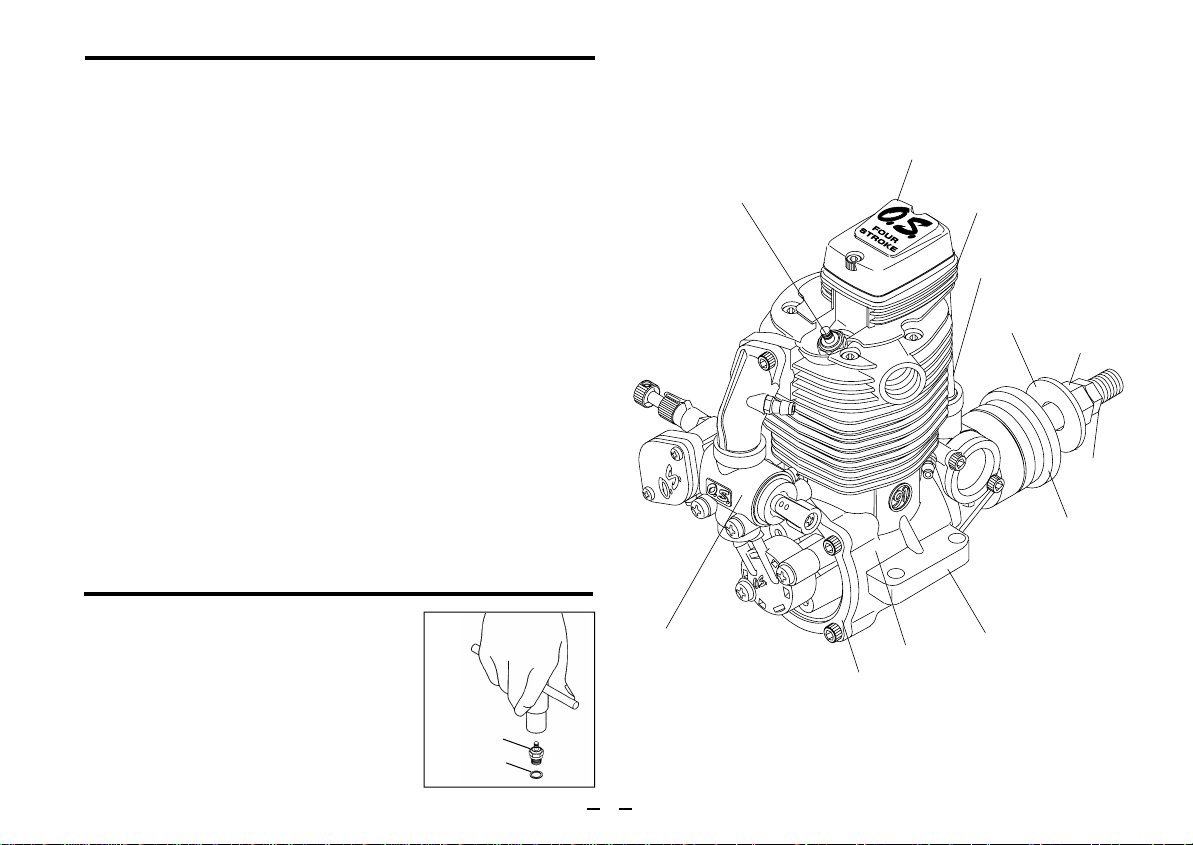
Glow plug Type F
Rocker Cover
Cylinder Head
Push Rod Cover
Propeller Washer
Propeller Nut
Lock Nut
Drive Hub
INSTALLING THE GLOW PLUG
Carefully insert plug, with washer,
fingertight only, before final tightening
with the correct size plug wrench.
Glow plug
Washer
Carburettor Type 60N
5
Beam Mount
Crankcase
Cover Plate
Page 7
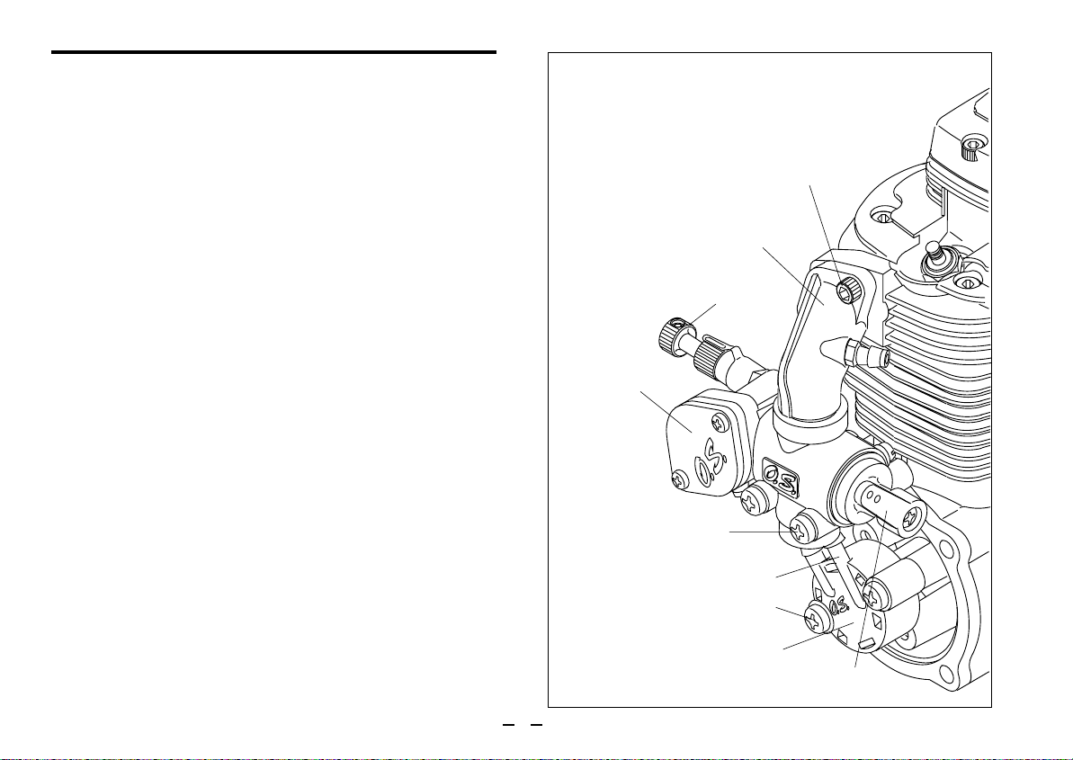
RELOCATION OF CARBURETTOR CONTROLS
FS-91S2-P
As supplied, the FS-70S2, FS-91S2 and FS-91S2-P have their
throttle lever on the right hand side and needle-valve control on
the left. However, where more convenient for certain installations,
these positions may be reversed after rotating the carburettor
through 180˚ horizontally.
Proceed as follows:
1.
Remove the intake pipe mounting screws from the cylinder head
(taking care not to lose the flange gasket [91S2/91S2-P] ) and
the carburettor mounting screws from the crankcase cover plate
bracket.
2.
Detach short tube connecting carburettor to pump unit (FS-91S
-P) and gently rotate the carburettor through 180° without
2
separating it from the intake pipe or removing the enclosed Oring seal.
3.
Re-install the complete sub-assembly of intake pipe and
Pressure Regulator
carburettor, making sure that adjoining surfaces are clean.
Tighten screws evenly and firmly but not excessively.
Remove pump mounting screws from the crankcase cover
4.
plate lugs, carefully rotate the pump clockwise one-quarter turn
and attach it to the second pair of lugs provided, taking care that
the central tube connecting the crank chamber to the pump
diaphragm chamber is not twisted.
Finally, make sure that all external tube connections are secure
5.
and do not leak.
Intake Pipe
Mounting Screw
Intake Pipe
Needle Valve
Carburettor
Mounting Screw
FueI Inlet
Pump Fixing Screw
PD-07 Pump
Throttle Lever
6
Page 8
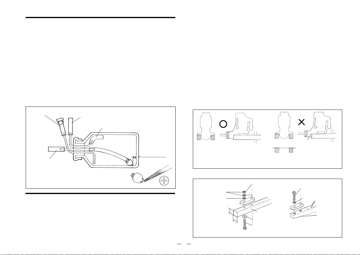
FUEL TANK
A fuel tank of approximately 300cc capacity is suggested. This
allows up to 12-13 minutes flying time, dependent upon the type of
fuel used, the size of the propeller and on the proportion of fullthrottle to part-throttle operation through the flight. Make sure that
the tank is well rinsed out with methanol or glow fuel before
installation and that the pickup weight is well clear of the bottom of
the tank when held vertically (see sketch). To prevent the pickup
from adhering to the tank wall under suction and restricting fuel
flow, slots may be filed in the end of the weight as shown.
Alternatively, a Bubbless type weight (Code No. 71531000) may
be used.
For filling or emptying tank
Air vent
Use thick-walled sillcone tubing
Make sure that these mounting beams are accurately aligned and
firmly integrated with the airframe, reinforcing the adjacent
structure to absorb vibration. Use 3.5mm or larger steel screws,
preferably Allen type hexagon socket head cap screws, with
washers and locknuts, for bolting the engine to the bearers.
As an alter native to wooden beam mounting, a special O.S. cast
aluminium radial motor mount, complete with 3.5mm mounting
screws, is available as an optional extra part, where front bulkhead
(firewall) type mounting is called for. Engine installation should, in
any case, be made in such a way that basic maintenance can be
conveniently carried out.
Make sure that the mounting beams are parallel and that their top
surfaces are in the same plane.
CORRECT
INCORRECT
10~15mm
To fuel inlet
INSTALLATION
Because these are powerful, large-displacement, single-cylinder
four-stroke-cycle engines, it is essential to use very substantial
engine mounting. Conventional wooden mounting beams should
be of rigid hardwood and of at least 15mm or 5/8-in square
section.
Front view
Top surfaces are in the same plane.
How to fasten the mounting screws.
3.5mm steel nuts
Spring washer or
lock washer
15mm min.
Hardwood mounting beams
Side view
15mm min.
7
Top surfaces are not
in the same plane.
Re-align the surfaces
as necessary
Tighten second nut firmly
down onto first nut.
Tighten this nut first.
Hardwood such as
cherry or maple.
Steel washer
4mm steel screw
O.S. radial motor mount
(cast aluminum)
Opposite beam
Top surfaces are not
in the same plane.
Engine does not
rest firmly.
3.5mm steel Allen screw
Spring washer
Page 9

EXHAUST HEADER PIPE & SILENCER
Fit these in the following sequence.
Screw the header pipe into the cylinder head until it " bottoms
", then unscrew sufficiently to achieve the desired exhaust
angle and tighten the locknut securely with a 14mm wrench.
Screw the silencer onto the outer end of the header pipe and
tighten the other locknut.
The application of a heatproof silicone sealant to the threads of
the exhaust system is recommended to reduce the risk of joints
loosening and the leakage of exhaust gases and oil residue.
Reminder:
Model engines generate considerable heat and contact with
the header pipe or silencer may result in a serious burn.
If you need to tighten the silencer joints, which may loosen
when they are hot, use a thick folded cloth for protection.
NEEDLE-VALVE EXTENSION
The needle-valve supplied with this engine is designed to
accept an extension so that, when the engine is enclosed in a
cowling, the needle-valve may be adjusted from the outside.
An L-shaped rod, of appropriate length, may be inserted in the
needle-valve knob centre hole and secured by tightening the
set-screw with a 1.5mm Allen key.
FUEL LINES
FS-70S2, FS-91S
<
For fuel line, use, heavy-duty silicone-rubber tubing of
approximately 2.5mm inside and 5.0mm outside diameter.
It is advisable to fasten connections with tube clips or secure
binding.
2
>
THROTTLE LINKAGE
Before connecting the throttle to its servo, make sure that the
throttle arm and linkage safely clear any adjacent part of the
airframe structure, etc., as the throttle is opened and closed.
Connect the linkage so that the throttle is fully closed when
the transmitter throttle stick and its trim lever are at their
lowest settings and fully open when the throttle stick is in its
fully-open position..
Carefully align the appropriate holes in the throttle arm and
servo horn so that they move symmetrically and smoothly
through their full travel.
Note:
8
Be sure to use a muffler-pressurized fuel feed
system.
Page 10
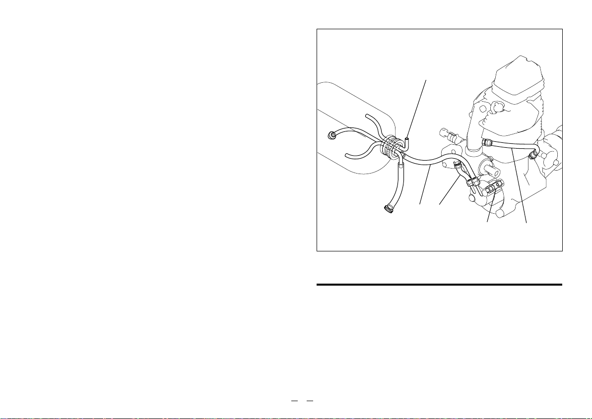
FS-91S2-P
<
The function of the various tubes connected to the engine and
tank (see sketch) are as follows:
Pipe A:
Pipe B:
Pipe C:
Pipe D:
Important
Pipes B, C and D are already installed when the engine is
shipped from the factory. If any of these pipes should
need to be replaced, due to damage or installation
problems, be sure to use tubing of the same dimensions
and quality as the originals.
For Pipe A (tank to pump) use similar heavy-duty siliconerubber tubing of approximately 2.5mm bore and 5.0mm
outside diameter.
Note:
Since the FS-91S2-P has a positively pumped fuel
supply, it does NOT require muffler pressurization.
>
To draw fuel from tank to pump nipple marked 'IN'.
To deliver fuel from pump nipple marked 'OUT' to
carburettor.
To connect crankcase breather nipple (behind
camshaft housing) to intake pipe.
To deliver crankcase pressure pulses to pump dia-
phragm.
Make sure there is adequate ventilation.
AB
D
C
CARE OF FUEL PUMP & REGULATOR
FS-91S2-P
<
A short preliminary period of part-throttle running is required
to ensure that the pump system functions correctly during the
running-in process. Set the throttle 75% open from the fullyclosed position and run the engine for 2-3 minutes. This will
ensure that the engine becomes rich enough when the
needle-valve is opened at full throttle during running-in.
>
9
Page 11

NEVER disassemble the fuel pump or pressure regulator.
•
Their original performance may not be restored after
reassembly.
DO NOT obstruct the small rectangular hole in the side of
•
the regulator cover.
DO NOT allow foreign matter to enter the fuel system. Dirt
•
inside the pump or regulator, no matter how small, may
obstruct the flow of fuel and prevent these components from
working properly.
NEVER insert anything into the inlet or outlet nipples in an
•
attempt to clear a suspected obstruction. (See CARE &
MAINTENANCE section at the back of this booklet.)
ALWAYS use fuel filters. Keep the fuel tank scrupulously
•
clean and filter all fuel as it enters the tank (e.g.via an
O.S.'Super-Filter' Code No.72403050) and use a good
quality in-line filter between the tank and pump. Remember
to inspect filter screens at regular intervals and rinse clean
as necessary.
NEVER use gasoline, kerosene, diesel fuel or other
•
petroleum products for cleaning the pump, regulator or fuel
lines. Silicone-rubber parts will be ruined by these materials.
Use only alcohol (methanol) or glow fuel for cleansing these
items.
PROPELLERS
The choice of propeller depends on the design and weight of
the aircraft and on the type of flying in which you will be
engaged. Determine the best size and type after practical
experimentation.
As a starting point, refer to the props listed in the
accompanying table.
Slightly larger, or even slightly smaller, props than those shown
in the table may be used, but remember that propeller noise will
increase if blade tip velocity is raised, due to higher revolutions
or a larger-diameter / smaller-pitch prop.
Warning:
Make sure that the propeller is well balanced. An
unbalanced propeller and / or spinner can cause serious
vibration which may weaken parts of the airframe or
affect the safety of the radio-control system.
DO NOT forget the WARNINGS and NOTES on propeller
and spinner safety given on pages 2,3 and 4.
FS-70S
2
Type Size (DxP
Stunt planes
Scale models
FS-91S2/91S2-P
11x9-10, 12x7-8, 12.5x6
13x8, 14x7, 11x7(3-blade
Type Size (DxP
Stunt planes
11x11-12, 12x10-12, 13x9
)
)
)
10
Scale models
13x9, 14x7, 15x6, 16x6
12x8(3-blade
)
Page 12

GLOWPLUGS
The FS-70S2, FS-91S2 and FS-91S2-P are supplied with
an O.S. Type F glowplug, specially designed for O.S. fourstroke engines.
The role of the glowplug
With a glowplug engine, ignition is initiated by the application
of a 1.5-volt power source. When the battery is disconnected,
the heat retained within the combustion chamber remains
sufficient to keep the plug filament glowing, thereby continuing
to keep the engine running. Ignition timing is 'automatic' :
under reduced load, allowing higher rpm, the plug becomes
hotter and, appropriately, fires the fuel/air charge earlier;
conversely, at reduced rpm, the plug become cooler and
ignition is retarded.
Glowplug life
Particularly in the case of very high performance engines,
glowplugs must be regarded as expendable items.
However, plug life can be extended and engine performance
maintained by careful use, i.e.:
Fit a plug suitable for the engine.
•
Use fuel containing a moderate percentage of nitromethane
•
unless more is essential for racing events.
Do not run the engine too lean and do not leave the battery
•
connected while adjusting the needle.
When to replace the glowplug
Apart from when actually burned out, a plug may need to be
replaced because it no longer delivers its best performance,
such as when:
Filament surface has roughened and turned white.
•
Filament coil has become distorted.
•
Foreign matter has adhered to filament or plug body has
•
corroded.
Engine tends to cut out when idling.
•
Starting qualities deteriorate.
•
FUEL
The FS-70S2, FS-91S2 and FS-91S2 -P should be
operated on a methanol based fuel containing not less than
18% castor-oil, or a top quality synthetic lubricant (or a
mixture of both), plus a small percentage (5-15%) of
nitromethane for improved flexibility and power. The
carburettor is adjusted at the factory for a fuel containing 20%
lubricant and 10% nitromethane.
Some commercial fuels also contain coloring additives as an
aid to fuel level visibility. In some cases, these additives have
indicated slightly negative effects on performance. We would
suggest that you use such fuels only if you are satisfied that
they do not adversely affect running qualities when compared
with familiar standard fuels.
When changing to a fuel brand or formula that is different
from the one to which you are accustomed, it is a wise
precaution to temporarily revert to in-flight running-in
procedures, until you are sure that the engine is running
entirely satisfactorily.
11
Page 13

Reminders:
AII model engine fuel is poisonous.Do not allow it to
come into contact with the eyes or mouth. Always store it
in a clearly marked container and out of the reach of
children.
Though not as volatile as gasoline, model engine fuel is
also highly inflammable.
Keep it away from on open flame, excessive heat,
sources of sparks, or anything else that might ignite it.
Smoking is firmly discouraged.
PROPELLER & SPINNER ATTACHMENT
There is a risk, particularly
with powerful four-stroke
engines, of the propeller flying
off if the prop nut loosens due
to detonation ("knocking") in
the combustion chamber when
the engine is operated too
lean, or under an excessively
heavy load.
Obviously, this can be very hazardous. To eliminate such
dangers, the O.S. Safety Locknut Assembly was devised. Fit
this as follows:
1.
Ream the propeller shaft hole to 8.1mm bore with an
appropriate reamer, checking that the hole is exactly
centered.
2.
Fit the prop to the engine shaft, followed by the retaining
washer and prop nut and tighten firmly with a 14mm
wrench.
Propeller Washer
Propeller Nut
Lock Nut
3.
Add the special tapered and slotted locknut and secure
with a 12mm wrench while holding the prop nut with the
14mm wrench.
Since the FS-70S2, FS-91S2 and FS-91S2-P are
intended to be started with an electric starter, the addition
of a spinner assembly for centering the starter sleeve is
desirable. Special propeller locknut sets are available for
use with spinners.
TYPE 60R, 60P AND 60N CARBURETTOR
Two adjustable controls are provided on these carburettors.
They are as follows:
The Needle Valve
•
This is used to establish the fuel/air mixture strength
required for full power when the throttle is fully open.
The Mixture Control Screw
•
This is used to establish the mixture strength required for
steady idling and a smooth transition to medium speeds.
(The varying mixture strength required between part-throttle
and full-throttle running is automatically adjusted by coupled
movement of the throttle.)
The sequence in which these controls are adjusted is
explained in the succeeding sections, under Starting,
Running-in and Idling Adjustment.
12
Page 14

STARTING
The FS-70S2, FS-91S2 and FS-91S2-P are not fitted with
manual choke controls, as they are intended for use with an
electric starter only.
A high-torque electric starter not only makes starting the engine
much easier, it dispenses with the need for a choke valve by
turning the engine over fast enough to cause the fuel pump to
prime the cylinder automatically.
Check that the current to the glowplug is switched off.
1.
Check that the polarity of the starter battery leads rotates the
2.
engine counter-clockwise when viewed from the front.
Open the needle-valve 3-3.5 turns from the fully closed
3.
position and temporarily set the throttle in the fully open
position.
Apply the starter and press the starter switch for 5-6
4.
seconds, or until fuel is seen to emerge from the exhaust
outlet, indicating that the cylinder is now primed.
5.
Close the throttle-arm to within 15-20° of the fully closed
position and slowly turn the prop "backwards" (clockwise) by
hand approximately 1.5 turns until it is arrested by
compression.This is to enable the kinetic energy of the prop
to subsequently assist the starter through the compression
stroke to start the engine.
6.
Energize the glowplug and apply the starter. If the starter
fails to rotate the engine completely, this may be due to the
cylinder being over-primed, or to the starter battery being
insufficiently charged.
Check these conditions and, instead of pressing the starter
7.
button after applying the starter, have the starter spinning
before applying it to the engine, to give it a "running start".
When the engine starts, slowly open the throttle, leaving
the needle-valve at its rich starting setting to promote cool
running conditions.
However, if the engine slows down because the mixture is
excessively rich, the needle-valve may be closed a little to
speed it up until it runs evenly.
Now disconnect current to the glowplug and gradually close
8.
the needle-valve so that revolutions are increased. Make
adjustments to the needle in small steps. Abrupt changes
at this stage are likely to cause the engine to stall. Restart
the engine by simply applying the starter with the glowplug
re-energized and the throttle at its starting setting.
RUNNING-IN ("Breaking-in")
For long life and peak performance, every engine needs
special treatment when new, known as "running-in" or
"breaking-in". This is a process during which the engine is
operated under strictly controlled conditions at the beginning
of its life, in order to avoid the risk of immediate damage to
certain components through becoming overheated or stressed
and to help working surfaces to become smoothed and
aligned for maximum mechanical efficiency thereafter.
With some engines, this can require a tediously protracted
period of bench running, but, as O.S. engines are
manufactured to fine tolerances and from the finest quality
materials, a relatively brief running-in period is sufficient and
can be completed with the engine installed in the aircraft.
The recommended procedure is as follows :
13
Page 15

1.
Start and adjust the engine as detailed in the starting
instructions.
Now open the throttle fully and run the engine for no more
2.
than 5 seconds with the needle-valve tuned to produce near
maximum r.p.m., then, immediately, slow the engine down
again by opening the needle-valve approximately one turn.
The rich mixture, so induced, will cool the engine, at the
same time providing increased of lubrication.
Allow the engine to run like this for about 10 seconds, then
3.
close the needle-valve again to speed it up to near
maximum rpm for another 5 seconds.
4.
Repeat this process, alternately running the engine fast and
slow by means of the needle-valve, while keeping the
throttle fully open, then begin to extend the short periods of
high-speed operation until two full tanks of fuel have been
consumed.
WARNING:
When ground running the engine, avoid dusty or sandy
locations. If dust or grit is drawn into the engine, this
can have a ruinous effect, drastically shortening
engine life in a matter of minutes.
Following the initial running-in session, check for any
5.
looseness in the installation due to vibration, then allow the
engine a period of moderately rich operation in flight.
For the first flight, have the needle-valve set on the rich
6.
side and adjust the throttle trim on the transmitter so that
the engine does not stop when the throttle is closed to the
idling setting.
With each successive flight, close the needle-valve very
7.
slightly until, at the end of about 10 flights, the needle is set
for full power. Do not "over-lean" the mixture in an attempt
to extract more power.
RUNNING-IN (continued)
If overheating should be suspected at any time during flight
8.
(i.e.if the engine begins to "labor") reduce power by partially
closing the throttle and land the aircraft to enable the
needle-valve to be readjusted to a richer setting.
Note:
Remember that, when the engine is not yet fully run-in,
the carburettor cannot be expected to give its best
response in flight. Abrupt operation of the throttle, for
example, may cause the engine to stall. Therefore, at this
time ,the aircraft should, as far as is possible, be flown at
an altitude sufficient to enable an emergency landing to
be safely made if the engine stops.
Once the engine has demonstrated that it can be safely
9.
operated at full power, the carburettor can be adjusted for
optimum throttle response, following the instructions given
in the next section.
14
Page 16

IDLING MIXTURE ADJUSTMENT
Start the engine, open the throttle fully and set the needle-
1.
valve slightly rich (30-45°) from the highest r.p.m. setting.
2.
Close the throttle to the idling position. Allow the engine to
idle for about 5 seconds, then reopen the throttle. The
engine should accelerate smoothly back to full speed.
If, instead, the engine responds sluggishly and emits an
3.
excess of white smoke from the exhaust, the idling mixture
is too rich. Turn the mixture control screw approx. 45°
clockwise to lean the idling mixture.
On the other hand, if the engine hesitates before picking up
4.
speed or even ceases firing completely, the idling mixture
is likely to be too lean. Turn the mixture control valve 90°
counter-clockwise to substantially enrich the mixture, then
back again 45° clockwise.
In paragraphs 3 and 4 above, the 45° total movements are,
5.
of course, approximate. It will be necessary to fine-tune the
mixture control screw 10-15° at a time to reach the best
setting for optimum throttle response.
Continue re-checking the idling mixture setting until the
6.
engine responds smoothly and positively to operation of
the throttle at all times.
Realignment of Mixture Control Screw
In the course of making readjustments, it is just possible that
the mixture control screw may be inadvertently screwed in or
out too far and thereby moved beyond its effective range.
The factory setting can be re-established as follows:
Set the throttle at the fully closed position.
Now carefully rotate the mixture control screw clockwise until
it stops. Finally, turn the mixture control screw back exactly
3turns for the FS-70S2, 2 1/2 turns for the FS-91S2and 2
turns for the FS-91S2-P.
VALVE ADJUSTING
ALL O.S. four-stroke engines have their valve(tappet)
clearances correctly set before they leave the factory. However,
if, after many hours of running time have been logged, a loss of
power is detected, or if the engine has to be disassembled or
repaired as a result of an accident, valve clearances should be
checked and readjusted, as necessary. O.S. Valve Adjusting
Tool Kit is available as optional accessory.
The kit comes in a plastic case and includes:
(Code No.72200060)
• Feeler gauge 0.04mm
• Feeler gauge 0.1mm
• Hex. key 1.5mm
• Wrench 5mm
15
Page 17

Note:
Valve clearances of all O.S. four-stroke-cycle engines
must be checked and reset ONLY WHEN THE ENGINE IS
COLD. Procedure is as follows.
(1)
Remove the cover from the rocker-box on top of the
1.
cylinder-head, using the correct size Allen hex key.
2.
Turn the propeller counter-clockwise until compression is
first felt, then turn it a futher quarter revolution. At this point,
both valves should be closed. (If the prop driver ('drive
hub') of your engine is engraved with a letter 'T', this mark
should now be at the top.)
The standard valve clearance, on both inlet and exhaust
3.
valves, is between 0.04mm and 0.10mm(0.0015-0.004
inch), measured between valve stem and rocker arm. Use
the 0.04mm and 0.10mm feeler gauges to check
clearances. (See Fig.1.)
Note:
If the gap is found to be less than 0.04mm, it is not
necessary to readjust the clearance if the engine has
good compression and starts easily.
Equally, if the gap exceeds
0.10mm but is not more than
0.14mm (i.e. the thickness of
both feeler gauges inserted
0.04mm
Feeler Gauge
Rocker Arm
Valve
together), it is not essential to
readjust the clearance if the
engine runs satisfactorily.
Fig.1
If a clearance is found to be outside either of these limits,
(2)
it should be reset as follows.
Carefully loosen the locknut
1.
on rocker-arm 1/4-1/2 turn
Locknut
Loosen approx.
1/4 to 1/2 turn.
with 5mm wrench.
(Fig.2.)
Turn adjusting-screw approx.
2.
1/2 turn counter-clockwise to
Adjusting
Screw
Turn approx.
1/2 turn.
open gap, using appropriate
tool -i.e. Allen hex key.
(Fig.3.)
Insert 0.04mm feeler gauge
3.
between valve stem and
Turn with fingers
until it stops.
Allen Key
rocker-arm and gently turn
adjusting screw clockwise
until it stops.(Fig.4.)
0.04mm Feeler
Gauge
Wrench
Fig.2
Fig.3
Fig.4
16
Page 18

Re-tighten locknut while
4.
holding adjusting screw
stationary. (Fig.5.)
Remove 0.04mm feeler,
5.
rotate prop through two
revolutions and recheck
gap.
Fig.5
If clearance is correct, loosen the locknut on the other
6.
rocker-arm and repeat steps 1 to 5 above. Finally, replace
rocker box cover.
Remember:
Excessive valve clearance will cause loss of power, due
to valve (s) not opening sufficiently. On the other hand, a
total loss of clearance may cause difficult starting due to
valves not closing properly, resulting in loss of
compression.
Hold at the
screw head.
Tighten
Locknut.
CARE AND MAINTENANCE
Please pay attention to the matters described below to ensure
that your engine serves you well in regard to performance,
reliability and long life.
As previously mentioned, it is vitally important to avoid
operating the engine in conditions where dust, disturbed by
the propeller, may be deposited on the engine and enter its
working parts. Also, remember to keep your fuel container
closed to prevent foreign matter from contaminating the fuel.
Do not forget to clean the fuel filters periodically and, from
time to time, unscrew the complete needle-valve assembly
from the carburettor and remove any foreign matter that has
accumulated in this area.
If these precautions are neglected, restriction of fuel flow may
cause the engine to cut out, or the fuel/air mixture to become
too lean causing the engine to overheat.
The use of modern high-performance alcohol based model
engine fuels, while promoting cooler running, improved antidetonation combustion and increased power, have the
disadvantage of causing bottom end corrosion in a four-stroke
engine. This is due to the acidic by produvts of combustion that
accumulate in the engine's crankcase and are not flushed out
by fresh air/fuel mixture as in the case of a two-stroke engine.
The use of nitromethane in the fuel can also contribute to the
problem. As noted earlier, the FS-70S2, FS-91S2 and FS91S2-P have their most vulnerable components protected
against such attack but, as a primary defence, users are
advised, once again, to avoid running the engine on too lean a
mixture and by making sure that the engine is purged of
contaminants as much as possible.
17
Page 19

Do not leave unused fuel in the engine at the conclusion of a
day's flying. Accepted practice is to cut off the fuel supply
while the engine is still running - at full throttle - then, expel
as much fuel residue as possible by turning the engine over
for 5-10 seconds with the electric starter.
Finally, inject some after-run oil through the glowplug hole and
turn the engine over several times by hand.
When the engine is not to be used for some months (for
example, as between flying seasons) a worthwhile precaution
is to remove it from the airframe and, after washing off the
exterior with alcohol (not gasoline or kerosene) to carefully
remove the fuel pump, carburettor with intake pipe and all
silicone tubes and put them safely aside.
Make sure that the engine is reasonably clean externally, then
remove the glowplug and immerse the engine in a container
of kerosene. Rotate the crankshaft while the engine is
immersed. If foreign matter is visible in the kerosene, rinse the
engine again in clean kerosene, before removing it, vigorously
shaking off the excess and wiping it dry.
CARE & MAINTENANCE (laying up)
The fuel pump assembly, carburettor/pressure-regulator and
silicone tubes must be cleansed separately in methanol or
glow fuel. On no account must they come into contact with
kerosene.
Before completely reassembling the engine, make sure that
no kerosene remains inside that could find its way into the
pump unit, carburettor, etc. Inject, sparingly, preserving oils,
rust inhibitors, etc. unless approved for silicone-rubber
products.
An appropriate alternative here may be one of the high-quality
synthetic lubricating oils.
Finally, seal the engine in a heavy polyethylene bag until
required for refitting to the airframe.
Debris tends to
accumulate in
this area
18
Page 20

O.S. GENUINE PARTS & ACCESSORIES
RADIAL MOTOR MOUNT
■
For FS-70S2
(71905000)
For FS-91S2/S2-P
(71901100)
PROPELLER LOCKNUT SET
■
(45910200 For Spinner)
BOOSTER CABLE SET
■
(72200110)
O.S.GLOW PLUG TYPE F
■
(71615009)
BOOSTER TERMINAL KIT
■
(72200130)
SUPER FILTER (L
■
(72403050)
)
EX EXHAUST HEADER PIPES
■
(72109500)
Inside
FLEXIBLE EXHAUST PIPES
■
BUBBLESS WEIGHT
■
(71531000)
(72109600)
Outside
Code.No.
72108100
72108110
72108120
72108130
LONG SOCKET WRENCH
■
WITH PLUG GRIP
(71521000)
Type
1111A
1111B
1111C
1111D
Length
(mm)
120
240
170
330
19
Page 21

FS-70S2 EXPLODED VIEW
5
C.M2.6X12
2
C.M3.5X20
3
-2
3
-1
5
-4
5
-3
5
-2
(
)
C.M3.5X15
3
4
-1
4
4
-2
6
-4
6
-3
6
-2
6
20
1
9
C.M2.6X8
N.+M3X22
9
-1
0
C.M3.5X8
8
5
-1
-
9
-2
0
-2
0
t
-1
u
g
-1
y
=
q
w
e
r
i
6
-1
7
\
a
-2
a
a
-1
a
-2
s
h
f
d
p
o
g
]
[
p
C.M2.6X8
Type of screw
✽
C…Cap Screw B…Binding Head Screw M…Oval Fillister-Head Screw
F…Flat Head Screw N…Round Head Screw S…Set Screw
Page 22

FS-70S2 PARTS LIST
3
3
4
4
5
5
5
5
6
6
6
6
9
9
No.
1
2
3
-1
-2
4
-1
-2
5
-1
-2
-3
-4
6
-1
-2
-3
-4
7
8
9
-1
-2
0
=
Code No.
4 5913 000
4 5904 210
4 5961 400
4 5961 410
4 5761 600
4 5361 000
4 5361 100
4 5061 202
4 5960 001
4 5960 100
4 5960 210
4 5960 310
4 5960 400
4 5960 011
4 5960 110
4 5960 210
4 5960 310
4 5960 400
4 4004 110
4 4004 010
4 4068 000
4 4068 100
4 5771 000
4 4082 000
4 4014 010
4 4003 400
Description
Screw Set
Rocker Cover
Rocker Support Assembly
Rocker Support
Rocker Arm Retainer(2pc./1pair
Rocker Arm Assembly(1pair
Rocker Arm(1pc.
Tappet Adjusting Screw
Intake Valve Assembly(1pair
Intake Valve(1pc.
Valve Spring(1pc.
Valve Spring Retainer(1pc.
Split Cotter(2pc./1pair
Exhaust Valve Assembly(1pair
Exhaust Valve(1pc.
Valve Spring(1pc.
Valve Spring Retainer(1pc.
Split Cotter(2pc./1pair
Cylinder Head
Cylinder Head(w/valve
Intake Pipe Assembly
Intake Pipe
Breather Nipple
Carburettor Complete(60R
Head Gasket
Piston Ring
)
)
)
)
)
)
)
)
)
)
No.
Code No.
4 4003 200
q
4 4006 000
w
4 5605 000
e
4 4003 100
)
)
)
)
)
r
4 4007 010
t
4 4002 020
y
u
4 5630 000
i
4 4001 010
4 5771 000
o
p
4 5231 100
[
4 5962 010
]
4 4001 100
4 4066 000
\
4 4066 100
a
4 4066 110
a
-1
a
2 4881 824
-2
s
4 5564 000
d
2 6731 002
f
4 6120 000
g
4 4008 000
2 9008 219
g
-1
4 5910 100
h
4 5925 010
4 5925 100
4 5926 000
7 1615 009
The specifications are subject to alteration for improvement without notice.
Piston
Piston Pin
Connecting Rod
Cylinder Liner
Cover Plate
Crankshaft
Crankshaft Ball Bearing(R
Crankcase
Breather Nipple
Camshaft Ball Bearing(1pc.
Camshaft
Cam Cover
Push Rod(2pcs.
Push Rod Cover Assembly(2pcs.
Push Rod Cover(1pc.
Push Rod Cover "O" Ring(2pcs.
Cam Follower(2pcs.
Crankshaft Ball Bearing(F)
Thrust Washer
Drive Hub
Woodruff Key
Locknut Set
Silencer(F-4020)
Silencer Body
Exhaust Header Pipe Assembly
Glow Plug Type F
Description
)
)
)
)
)
)
)
21
Page 23

FS-91S2 EXPLODED VIEW
5
C.M2.6X12
2
C.M3.5X20
3
-2
3
-1
5
-4
5
-3
5
-2
(
)
C.M3.5X15
3
4
-1
4
4
-2
6
-4
6
-3
6
-2
6
22
1
9
C.M2.6X8
N.+M3X22
9
-1
0
C.M3.5X8
8
5
-1
9
-2
0
-2
0
r
-1
y
g
-1
t
-
u
=
q
w
e
i
6
-1
7
\
a
-2
a
a
-1
a
-2
s
h
f
d
p
o
g
]
[
p
C.M2.6X8
Type of screw
✽
C…Cap Screw B…Binding Head Screw M…Oval Fillister-Head Screw
F…Flat Head Screw N…Round Head Screw S…Set Screw
Page 24

FS-91S2 PARTS LIST
3
3
4
5
No.
1
2
3
-1
-2
4
4
-2
5
-1
5
5
5
6
6
6
6
6
7
8
9
9
9
0
0
0
-
=
4 5913 000
4 5904 210
4 5961 400
4 5961 410
4 5761 600
4 5361 000
4 5361 100
-1
4 5061 202
4 5960 000
4 5960 100
4 5960 200
-2
4 5960 300
-3
4 5960 400
-4
4 5960 010
4 5960 110
-1
4 5960 200
-2
4 5960 300
-3
4 5960 400
-4
4 5904 110
4 5904 010
4 5968 200
4 5968 210
-1
4 5771 000
-2
4 5984 000
4 6115 000
-1
4 5581 700
-2
4 5903 400
4 5903 200
Code No.
Description
Screw Set
Rocker Cover
Rocker Support Assembly
Rocker Support
Rocker Arm Retainer(2pc./1pair
Rocker Arm Assembly(1pair
Rocker Arm(1pc.
Tappet Adjusting Screw
Intake Valve Assembly(1pair
Intake Valve(1pc.
Valve Spring(1pc.
Valve Spring Retainer(1pc.
Split Cotter(2pc./1pair
Exhaust Valve Assembly(1pair
Exhaust Valve(1pc.
Valve Spring(1pc.
Valve Spring Retainer(1pc.
Split Cotter(2pc./1pair
Cylinder Head
Cylinder Head(w/valve
Intake Pipe Assembly
Intake Pipe
Breather Nipple
Carburettor Complete(60P
Carburettor Rubber Gasket
Carburettor Fixing Screw(2pcs.
Piston Ring
Piston
)
)
)
)
)
)
)
)
)
)
No.
Code No.
4 5906 000
q
4 5605 000
w
4 6103 100
e
4 5907 020
r
)
)
)
)
)
)
4 5902 010
t
y
4 5530 030
u
4 5914 010
i
4 5901 010
o
4 5771 000
p
4 5231 100
[
4 5962 010
]
4 5901 110
\
4 5966 000
a
4 5966 100
a
4 5966 110
-1
a
2 4881 824
-2
s
4 5564 000
d
2 6731 002
f
4 6120 000
4 5908 000
g
g
2 9008 219
-1
h
4 5910 100
4 5925 010
4 5925 100
4 5926 000
7 1615 009
The specifications are subject to alteration for improvement without notice.
Piston Pin
Connecting Rod
Cylinder Liner
Cover Plate
Crankshaft
Crankshaft Ball Bearing(R
Gasket Set
Crankcase
Breather Nipple
Camshaft Ball Bearing(1pc.
Camshaft
Cam Cover
Push Rod(2pcs.
Push Rod Cover Assembly(2pcs.
Push Rod Cover(1pc.
Push Rod Cover "O"Ring(2pcs.
Cam Follower(2pcs.
Crankshaft Ball Bearing(F)
Thrust Washer
Drive Hub
Woodruff Key
Locknut Set
Silencer(F-4020)
Silencer Body
Exhaust Header Pipe Assembly
Glow Plug Type F
Description
)
)
)
)
)
)
)
23
Page 25

FS-91S
EXPLODED VIEW
2-P
C.M2.6X12
2
C.M3.5X20
3
-2
3
-1
5
-4
5
-3
5
-2
5
(
C.M3.5X15
4
)
3
4
-1
4
-2
6
-4
6
-3
6
-2
6
24
1
9
C.M2.6X8
N.+M3X22
C.M3.5X8
8
9
-1
0
9
-2
0
-2
-1
0
h
-1
y
t
r
5
-1
-
i
=
q
w
u
e
o
6
-1
7
a
s
-2
s
s
-1
s
-2
d
j
g
f
]
[
C.M2.6X8
\
[
p
h
✽
Type of screw
C…Cap Screw B…Binding Head Screw M…Oval Fillister-Head Screw
F…Flat Head Screw N…Round Head Screw S…Set Screw
Page 26

FS-91S2-P PARTS LIST
No.
1
2
3
3
-1
3
-2
4
4
-1
4
-2
5
5
-1
5
-2
5
-3
5
-4
6
6
-1
6
-2
6
-3
6
-4
7
8
9
9
-1
9
-2
0
0
-1
0
-2
=
Code No.
4 5913 000
4 5904 210
4 5961 400
4 5961 410
4 5761 600
4 5361 000
4 5361 100
4 5061 202
4 5960 000
4 5960 100
4 5960 200
4 5960 300
4 5960 400
4 5960 010
4 5960 110
4 5960 200
4 5960 300
4 5960 400
4 5904 110
4 5904 010
4 5968 000
4 5968 100
4 5771 000
4 5983 000
4 6115 000
4 5581 700
4 5903 400
4 5903 200
Description
Screw Set
Rocker Cover
Rocker Support Assembly
Rocker Support
Rocker Arm Retainer(2pc./1pair
Rocker Arm Assembly(1pair
Rocker Arm(1pc.
Tappet Adjusting Screw
Intake Valve Assembly(1pair
Intake Valve(1pc.
Valve Spring(1pc.
Valve Spring Retainer(1pc.
Split Cotter(2pc./1pair
Exhaust Valve Assembly(1pair
Exhaust Valve(1pc.
Valve Spring(1pc.
Valve Spring Retainer(1pc.
Split Cotter(2pc./1pair
Cylinder Head
Cylinder Head(w/valve)
Intake Pipe Assembly
Intake Pipe
Breather Nipple
Carburettor Complete(60N
Carburettor Rubber Gasket
Carburettor Fixing Screw(2pcs.
Piston Ring
Piston
)
)
)
)
)
)
)
)
No. Code No.
4 5906 000
q
4 5605 000
w
4 6103 100
e
7 2508 001
r
)
)
)
)
)
)
)
4 5907 010
t
4 5902 010
y
4 5530 030
u
i
4 5914 010
4 5901 010
o
p
4 5771 000
[
4 5231 100
]
4 5962 010
\
4 5901 110
a
4 5966 000
4 5966 100
s
s
4 5966 110
-1
2 4881 824
s
-2
d
4 5564 000
2 6731 002
f
4 6120 000
g
4 5908 000
h
2 9008 219
h
-1
j
4 5910 100
4 5925 010
4 5925 100
4 5926 000
7 1615 009
The specifications are subject to alteration for improvement without notice.
Piston Pin
Connecting Rod
Cylinder Liner
Pump Unit(PD-07
Cover Plate
Crankshaft
Crankshaft Ball Bearing(R
Gasket Set
Crankcase
Breather Nipple
Camshaft Ball Bearing(1pc.
Camshaft
Cam Cover
Push Rod(2pcs.
Push Rod Cover Assembly(2pcs.
Push Rod Cover(1pc.
Push Rod Cover "O"Ring(2pcs
Cam Follower(2pcs.
Crankshaft Ball Bearing(F
Thrust Washer
Drive Hub
Woodruff Key
Locknut Set
Silencer(F-4020)
Silencer Body
Exhaust Header Pipe Assembly
Glow Plug Type F
Description
)
)
)
)
)
)
.)
)
)
25
Page 27

CARBURETTOR EXPLODED VIEWS & PARTS LIST
S.3X3
60R(FS-70S2
1
-3
1
-2
1
1
N.+M3X22
-5
1
-4
9
1
-1
No. Code No. Description
4 5984 900
1
1
1
1
1
1
2
3
4
5
5
5
6
7
8
9
2 4081 970
-1
2 4981 837
-2
2 6381 501
-3
2 7381 940
-4
2 6711 305
-5
4 4082 100
4 5581 820
2 2681 953
4 5582 300
4 6066 319
-1
2 4881 824
-2
4 4082 200
2 7881 400
4 6115 000
4 5581 700
Needle Valve Assembly
Needle
Needle Valve Holder Assembly
Carburettor Body
Rotor Guide Screw
Fuel Inlet
Mixture Control Valve Assembly
"O" Ring (L) (2pcs.
"O" Ring (S) (2pcs.
Carburettor Rotor
Throttle Lever Assembly
Carburettor Rubber Gasket
Carburettor Fixing Screw
8
4
2
"O" Ring (2pcs.
Set Screw
Ratchet Spring
3
5
-2
5
)
)
)
5
-1
6
7
)
N.+M3X6
1
Type of screw
✽
C…Cap Screw B…Binding Head Screw M…Oval Fillister-Head Screw
F…Flat Head Screw N…Round Head Screw S…Set Screw
No. Code No. Description
1
1
1
1
1
5
5
S.3X3
-3
1
-2
1
-1
1
N.+M3X22
4 5984 900
1
2 4081 970
-1
2 4981 837
-2
2 6381 501
-3
2 7381 940
-4
2 6711 305
-5
2
4 5984 100
3
4 5581 820
4
2 2681 953
5
4 5582 300
4 6066 319
-1
2 4881 824
-2
4 5983 200
6
7
2 7881 400
8
4 6115 000
9
4 5581 700
The specifications are subject to alteration for improvement without notice.
26
8
4
1
-5
1
-4
2
5
9
Needle Valve Assembly
Needle
"O" Ring (2pcs.
Set Screw
Needle Valve Holder Assembly
Ratchet Spring
Carburettor Body
Rotor Guide Screw
Fuel Inlet
Mixture Control Valve Assembly
"O" Ring (L) (2pcs.
"O" Ring (S) (2pcs.
Carburettor Rotor
Throttle Lever Assembly
Carburettor Rubber Gasket
Carburettor Fixing Screw
60P(FS-91S2
3
-2
5
-1
5
6
7
)
)
)
)
N.+M3X6
Page 28

S.3X3
1
-3
1
-1
Type of screw
✽
1
1
-2
1
-5
1
-4
2
-1
N.+M3X22
9
60N(FS-91S2-P
2
8
3
5
-2
5
-1
4
5
6
C…Cap Screw B…Binding Head Screw
M…Oval Fillister-Head Screw
F…Flat Head Screw N…Round Head Screw S…Set Screw
Code No. Description
No.
1
1
-1
1
-2
1
-3
1
-4
1
-5
2
2
-1
3
4
5
5
-1
5
-2
6
7
8
9
2 7681 900
2 7681 970
2 4981 837
2 6381 501
2 7381 940
2 6711 305
4 5983 100
4 5582 400
4 5581 820
2 2681 953
4 5582 300
4 6066 319
2 4881 824
4 5983 200
2 7881 400
4 6115 000
4 5581 700
Needle Valve Assembly
Needle
"O" Ring (2pcs.
)
Set Screw
Needle Valve Holder Assembly
Ratchet Spring
Carburettor Body
60N Regulator Cover
Rotor Guide Screw
Fuel Inlet
Mixture Control Valve Assembly
"O" Ring (L) (2pcs.
"O" Ring (S) (2pcs.
)
)
Carburettor Rotor
Throttle Lever Assembly
Carburettor Rubber Gasket
Carburettor Fixing Screw
The specifications are subject to alteration for improvement without notice.
)
N.+M3X6
7
27
Page 29

THREE VIEW DRAWING
FS-70S2
■
Displacement
■
Bore
■
Stroke
■
PracticalR.P.M.
■
Output
■
Weight
Specifications
11.50cc/0.702cu.in.
25.8mm/1.016in.
22.0mm/0.866in.
2.000
~
12.000r.p.m.
1.1bhp/11.000r.p.m.
580g/20.4oz.
20.3 96.4
UNF5/16-24
55.8
50
21
39.6
58
28
66.3
44.7
Dimensions(mm)
Page 30

THREE VIEW DRAWING
FS-91S2
Displacement
■
Bore
■
Stroke
■
PracticalR.P.M.
■
Output
■
Weight
■
Specifications
14.95cc/0.912cu.in.
27.7mm/1.09in.
24.8mm/0.976in.
2.000
~
12.000r.p.m.
1.6bhp/11.000r.p.m.
640g/22.6oz.
29
Dimensions(mm)
Page 31

THREE VIEW DRAWING
FS-91S2-P
Displacement
■
Bore
■
Stroke
■
PracticalR.P.M.
■
Output
■
Weight
■
Specifications
14.95cc/0.912cu.in.
27.7mm/1.09in.
24.8mm/0.976in.
2.000
~
12.000r.p.m.
1.6bhp/11.000r.p.m.
650g/23.0oz.
30
Dimensions(mm)
Page 32

E
C
R
I
P
S
I
Y
O
T
I
N
L
A
U
Q
D
E
L
L
A
U
Q
E
N
U
&
P
E
R
F
O
R
M
A
N
C
E
C
Copyright 2000 by O.S.Engines Mfg. Co., Ltd. All rights reserved. Printed in Japan.
E
S
T
A
B
L
I
S
H
I
N
G
T
H
D
E
R
S
A
T
D
A
N
E
C
N
E
L
L
E
C
X
E
F
O
S
6-15 3-Chome Imagawa Higashisumiyoshi-ku
Osaka 546-0003, Japan
TEL. (06)6702-0225
FAX. (06) 6704-2722
URL : http://www.os-engines.co.jp
110104
 Loading...