

Page 1
It is of vital importance, before attempting to
operate your engine, to read the general
'SAFETY INSTRUCTIONS AND WARNINGS'
section on pages 2-5 of this booklet and to strictly
adhere to the advice contained therein.
Also, please study the entire contents of this
●
instruction manual, so as to familiarize yourself
with the controls and other features of the
engine.
●
Keep these instructions in a safe place so that
you may readily refer to them whenever
necessary.
It is suggested that any instructions supplied
●
with the vehicle, radio control equipment, etc.,
are accessible for checking at the same time.
Page 2

CONTENTS
SAFETY INSTRUCTIONS AND WARNINGS
ABOUT YOUR O.S. ENGINE
INTRODUCTION, BASIC ENGINE PARTS
INSTALLATION OF THE CARBURETOR
ENGINE INSTALLATION
SUPER AIR CLEANER TYPE 102S
NOTES CONCERNING THE RECOIL STARTER
GLOWPLUG
TOOLS, ACCESSORIES, etc.
PRESSURIZED FUEL SYSTEM
STARTING,
RUNNING AND ADJUSTMENT
9
10~11
11
13~16
2~5
7
~
8~9
~
10
~
12
13
IF THE ENGINE FAILS TO START
VALVE ADJUSTING
6
CARE & MAINTENANCE
PARTS REPLACEMENT
8
GENUINE PARTS & ACCESSORIES
FS-40S-C EXPLODED VIEW
& PARTS LIST
FS-40S-CX EXPLODED VIEW
& PARTS LIST
CARBURETTOR EXPLODED
VIEW & PARTS LIST
THREE VIEW DRAWING
1
17
17~19
20
20
21
22
~
23
24~25
26
27~28
Page 3
SAFETY INSTRUCTIONS AND WARNINGS ABOUT YOUR O.S. ENGINE
Remember that your engine is not a "toy", but a highly efficient internalcombustion machine whose power is capable of harming you, or others, if it is
misused.
As owner, you, alone, are responsible for the safe operation of your engine, so act
with discretion and care at all times.
If at some future date, your O.S. engine is acquired by another person, we would
respectfully request that these instructions are also passed on to its new owner.
The advice which follows applies basically to ALL MODEL ENGINES and is
grouped under two headings according to the degree of damage or danger
which might arise through misuse or neglect.
WARNINGS
These cover events which
might involve serious (in
extreme circumstances, even
fatal) injury.
NOTES
These cover the many other
possibilities, generally less obvious
sources of danger, but which, under
certain circumstances, may also
cause damage or injury.
2
Page 4
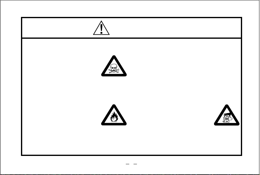
WARNINGS
•
Model engine fuel is
poisonous. Do not allow it
to come into contact with
the eyes or mouth. Always
store it in a clearly marked
container and out of the
reach of children.
Model engine fuel is also
•
highly flammable. Keep it
away from open flame,
excessive heat, sources of
sparks, or anything else
which might ignite it. Do not
smoke or allow anyone else
to smoke, near to it.
•
Never operate your engine in an
enclosed space. Model engines, like
automobile engines, exhaust deadly
carbon-monoxide. Run your engine
only in an open area.
Model engines generate
•
considerable heat. Do not
touch any part of your
engine until it has cooled.
Contact with the muffler
(silencer), cylinder head
or exhaust header pipe, in
particular, may result in a
serious burn.
3
Page 5

This engine is intended for model cars.
•
Do not attempt to use it for any other
purpose.
Mount the engine in your model
•
securely, following the manufacturers'
recommendations, using appropriate
screws and locknuts.
Fit an effective silencer (muffler).
•
Frequent close exposure to a noisy
exhaust (especially in the case of the
most powerful highspeed engines)
may eventually impair your hearing
and such noise is also likely to cause
annoyance to others over a wide area.
NOTES
•
The wearing of safety glasses is also
strongly recommended.
Take care that the glowplug clip or
•
battery leads do not come into contact
with rotating parts. Also check that the
linkage to the throttle arm is secure.
For their safety, keep all onlookers
•
(especially small children) well back
(at least 20 feet or 6 meters) when
preparing your model for running.
4
Page 6

•
To stop the engine, fully retard the
throttle stick and trim lever on the
trans-mitter, or, in an emergency, cut
off the fuel supply by pinching the fuel
delivery tube from the tank.
Do not attempt to disassemble the
•
recoil starter of the 40S-CX.
If you do so, the very strong spring
inside will be suddenly ejected. This
can be very dangerous.
Do not extend the starter cord more
•
than 40cm (16"). Do not abruptly
release the operating handle. Allow
the cord to rewind smoothly while
still holding the handle.
NOTES
•
Pull the operating handle straight out
when starting the engine, so that the
cord does not rub against the vehicle
body or engine. This will help prevent
the cord from being damaged by
abrasion or engine heat.
•
Warning! Immediately after a glowplugignition engine has been run and is still
warm, conditions sometimes exist
whereby it is just possible for the engine
to abruptly restart if it is rotated over
compression WITHOUT the glowplug
battery being reconnected.
5
Page 7
INTRODUCTION
These are overhead-valve four-strokecycle engines designed for 1/8 scale
radio-controlled model cars.
The engine is distinguished by a blackanodized crankcase and rocker-cover
and is supplied complete with an O.S.
Super Air Cleaner as standard.
The FS-40S-CX is equipped with a built
in recoil starter system which eliminates
the need for a separate electric starter
and starter battery.
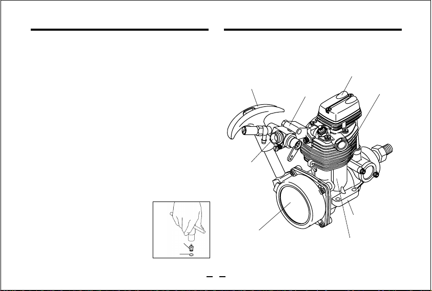
INSTALLING THE GLOWPLUG
Install the washer on the
glowplug and insert carefully into
cylinder-head, making sure that
it is not cross-threaded before
tightening firmly.
Glow plug
Washer
BASIC ENGINE PARTS
FS-40S-CX
Starter Handle
Carburettor
Recoil Starter
Assembly
6
Intake Pipe
Rocker Cover
Cylinder Head
Beam Mount
Crankcase
Page 8
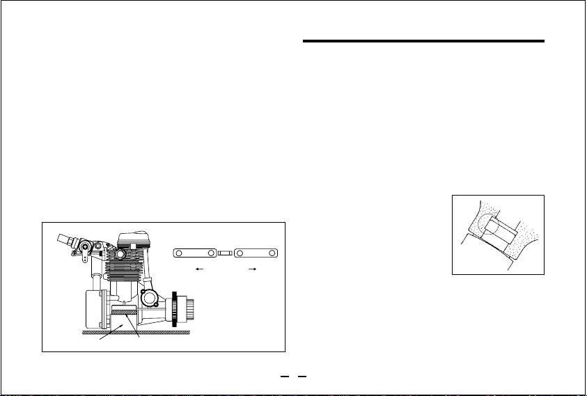
INSTALLATION OF THE CARBURETOR
As delivered, the engine has its carburetor lightly
fit into the intake boss. Secure it as follows.
Loosen the retainer screw,and remove the
1.
carburetor. Place the rubber gasket at bottom
of the intake boss, and rotate the carburettor
to its correct position and make sure that it is
pressed well down into the intake boss,
compressing the rubber gasket, before
retightening screw.
2.
Rotate the retainer screw gently until it stops,
then tighten a further 60-90˚.
Do not overtighten the screw as this will
damage the carburettor body.
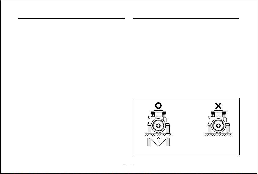
ENGINE INSTALLATION
Make sure that the vehicle's engine mounting
surfaces are level and in the same plane. Poor
installation may cause distortion of the crankcase,
bearings, etc., resulting in erratic running and loss
of performance. The recommended screws for
securing the engine are 3.5mm or 4-40 steel Allen
hexagon socket type. If existing holes in the
engine mount do not align perfectly with engine
mounting lugs, enlarge them slightly with a needlefile so that screws enter vertically.Avoid forcing the
screws.
Chassis
Chamfer inside edges of bearers.
7
Page 9
Secure with locknuts. If the bottom of the recoil
starter housing would otherwise touch the car
chassis, install the engine mount spacers
(supplied) between the engine's mounting lugs and
the engine mount. Use the M3.5x15 screws
provided. With some vehicles, it may be necessary
to make minor trimming modifications to chassis or
body when fitting the engine.
NOTE:
Where spacers are supplied joined in pairs
(see sketch), separate them as shown.
Either face may be placed downwards.
Mount Spacer
Separate
Engine Mount
Engine Mount Spacer
AIR CLEANER TYPE 102S
It has a single filter element and is intended
primarily for circuit racing, where conditions are
less damaging than the very dusty, loose surfaces
of off-road operation for which the double-element
Type 101 and 102 Air Cleaners are recommended.
The lower height of the Super Air-Cleaner 102S
also facilitates easier installation in cars where
available space may be restricted.
INSTALLATION OF AIR CLEANER
Carefully clean the
•
carburettor, removing any
old adhesive or sealant
that may have been
previously used on the
outside of the air intake.
Press the air cleaner body firmly over the
•
carburettor air intake. Make sure that the outer
rim of the air intake engages the internal
annular groove in the air cleaner: failure to do
so may result in the air cleaner falling off.
8
Page 10

Position the air cleaner correctly, so that it
•
does not foul the cylinder-head or obstruct the
needle-valve.
FIT THE FILTER ELEMENT
The element is already impregnated with a
•
special filter oil. As this oil is very sticky, take
care, when handling it, to prevent dust or dirt
from adhering to the element. If your fingers
become contaminated, wash them with soap
and water.
During storage, the oil may have become
•
unevenly dispersed through the element. This
will be indicated if the blue colour of the element
material appears patchy.
In this case, place the
element in a small plastic
bag and gently rub it
between finger and thumb to
redistribute the oil.
Insert beneath flange
REPLACEMENT OF ELEMENT
It is advisable to replace the filter element with
•
a new one after not more than one hour of
running time. Always remove contaminated
elements carefully, to ensure that dirt cannot
enter the carburettor.
NOTES CONCERNING THE RECOIL STARTER
REMINDER!
◆
Do not attempt to disassemble the recoil
starter. If you do so, the very strong spring
inside will be suddenly ejected. This can be
very dangerous.
◆
Do not extend the starter cord more than
40cm(16"). Do not abruptly release the
operating handle. Allow the cord to rewind
smoothly while still holding the handle.
◆
Pull the operating handle straight out when
starting the engine, so that the cord does
not rub against the vehicle body or engine.
9
( FS-40S-CX ONLY)
Page 11

◆
This will help prevent the cord from being
damaged by abrasion or engine heat.
◆
Try to avoid spilling fuel over the starter unit
and its cord. Some fuels have a detrimental
effect on these parts.
◆
The starter prevents the engine from being
rotated in the wrong direction. The unit will
be damaged if you attempt to force the
flywheel in the opposite direction (i.e.
clockwise when viewed from the crankshaft
end).
NOTE:
Because, in the interests of personal safety,
dismantling of the starter mechanism is
strongly discouraged, the Recoil Starter is
available for replacement only as a preassembled unit. However, some related parts,
such as Starting Shaft and Rear Adaptor, are
obtainable separately. (See Parts List.)
GLOWPLUG
The FS-40S-C and FS-40S-CX are supplied with
an O.S. Type F glowplug, specially designed for
O.S. four-stroke engines.
The role of the glowplug
With a glowplug engine, ignition is initiated by
the application of a 1.5-volt power source. When
the battery is disconnected, the heat retained
within the combustion chamber remains
sufficient to keep the plug filament glowing,
thereby continuing to keep the engine running.
Ignition timing is 'automatic' : under reduced
load, allowing higher rpm, the plug becomes
hotter and, appropriately, fires the fuel/air charge
earlier; conversely, at reduced rpm, the plug
become cooler and ignition is retarded.
Glowplug life
Particularly in the case of very high performance
engines,
expendable items.
10
glowplugs must be regarded as
Page 12

However, plug life can be extended and engine
performance maintained by careful use, i.e.:
Install a plug suitable for the engine.
•
Use fuel containing a moderate percentage of
•
nitromethane unless more is essential for
racing events.
Do not run the engine too lean and do not
•
leave the battery connected while adjusting the
needle.
When to replace the glowplug
Apart from when actually burned out, a plug may
need to be replaced because it no longer
delivers its best performance, such as when:
Filament surface has roughened and turned
•
white.
Filament coil has become distorted.
•
Foreign matter has adhered to filament or plug
•
body has corroded.
Engine tends to cut out when idling.
•
Starting qualities deteriorate.
•
TOOLS, ACCESSORIES, etc.
The following items are necessary for operating
the engine.
FUEL
Use only top quality methanol-based model engine fuel.For
consistent performance and long engine life, it is advisable
to use fuel containing A T LEAST 18% lubricant. This engine
is designed to run on both low and high nitromethane content
fuels,i.e. from mild mixtures containing small percentage of
nitromethane, up to high-speed racing fuels containing 40%
nitromethane. Generally, power output is increased up to
a certain point as the nitromethane content of the fuel is
increased. As a starting point, we recommend a fuel
containing 10-20% nitromethane, changing to a fuel
containing more nitro only if necessary. When the nitro
content of the fuel is increased or the brand of fuel is
changed, it is advisable to initially run the engine with a richer
needle-valve setting, so that the optimum setting for the new
fuel may be rechecked as described in the RUNNING-IN
paragraphs. When engines are run at very high speeds and
on high-nitro fuels, glowplug elements do not last so long.
11
Page 13

as described in the RUNNING-IN paragraphs.
When engines are run at very high speeds and on
high-nitro fuels, glowplug elements will not last as
long.
Reminder!
Model engine fuel is poisonous. Do not
allow it to come into contact with the
eyes or mouth. Always store it in a
clearly marked container and out of the
reach of children.
Model engine fuel is also highly
flammable. Keep it away from open flame,
excessive heat, sources of sparks, or
anything else which might ignite it.
BATTERY INTEGRATED GLOWPLUG HEATER
Commercialy available handy
glowplug heater in which the
glowplug battery and battery
leads are integrated.
ELECTRIC STARTER AND STARTER BATTERY
Use a 12-volt electric starter
with suitable battery for starting
the engine.(FS-40S-C)
LONG SOCKET WRENCH
Recommended for easy removal
and replacement of the angled
and recessed glowplug, the
O.S.Long Socket Wrench
incorporates a special grip.
FUEL PUMP
For filling the fuel tank, a simple,
polyethylene "squeeze" bottle,
with a suitable spout, is required.
SILICONE FUEL LINE
Heatproof silicone tubing of
approx. 5mm o.d. and 2mm i.d.
is required for the connection
between the fuel tank and
engine.
12
Page 14

PRESSURIZED FUEL SYSTEM
●
The somewhat violent changes of vehicle
attitude that occur in off-road running,
combined with the fact that, in buggy type
cars, the fuel tank is often located some
distance from the carburettor, means that fuel
'head' at the carburettor can vary and upset
running.Therefore,it is recommended that a
muffler pressurized fuel feed system be used.
●
Never run your vehicle without the air cleaner.
Dust and dirt that may otherwise be drawn into
the engine will rapidly shorten its life.
Fuel Tank
Connect suitable length of
Silicone tubing between fuel
tank and silencer.
Silencer
Silicone tubing
ST ARTING, RUNNING AND ADJUSTMENT
In the interests of a long working life and high
performance, every internal-combustion engine
needs to be "run-in" (or "broken-in" as the
procedure is also known). This means giving the
engine extra care and attention during the first
hour or so of its operational life. New parts need
to become "bedded-in", i.e. smoothed and
aligned to reduce friction and avoid distortion.
For this to take place, the engine must not be
overloaded or run too fast. The essential
ingredients here, are ample lubrication and
cooling. Such a condition is achieved by having
the engine operate on an extremely rich needlevalve setting : the excess oil not only provides an
abundance of lubrication; it also conducts away
heat from the surrounding metal and this is
further assisted by the partial evaporation of the
alcohol content of the fuel.
13
Page 15

With an aircraft engine, cooling is also aided, in
large measure, by the slipstream and some
model car enthusiasts elect to carry out initial
running-in, in this way by bench-mounting the
engine and temporarily fitting it with an aircraft
type drive hub and propeller. In the case of the
O.S. FS-40S-C, however, the fact that it is a fourstroke engine with inlet pipe and carburettor
mounted high on the cylinder-head, means that
each charge of rich, cooling, fuel-air mixture is
admitted directly into the cylinder, instead of
being pre-heated in a lengthy journey via the
crankcase, as in the usual two-stroke model car
unit. With extra care, the FS-40S-C can,
therefore, be run-in ready-installed in the car.
●
Turn the needle-valve gently clockwise until it
stops. Do not use force to turn the needle
beyond this point. Now reopen it 1 3/4 turns.
●
Set the throttle-stop screw
so that the minimum
throttle opening (idle
setting) is approximately
2mm.
●
Switch on the transmitter, followed by the
receiver. Close the throttle stick and open the
throttle trim lever to the idle setting.
●
Connect the glowplug battery and apply the
electric starter. As soon as the engine starts,
disconnect the glowplug battery, keeping the
engine running slowly on the rich needle setting. (If necessary, make a slight readjustment
to the throttle stick to keep the engine idling
steadily.) If the engine stops, allow it to cool for
a minute or two before restarting it. In fact, short
runs, interrupted by brief cooling-off periods is
good practice during running-in.
14
2mm
Page 16

Front
Rotating Direction
Rear
■
In case of FS-40S-CX
●
Press choke button on car's fuel tank
sufficient to prime carburetor. (Do not
overprime!)
●
Making sure that glowplug
remains switched off,
check that starter handle
can be pulled out, then reconnect plug and operate
starter briskly until engine
starts.
Starter Handle
Do not extend the starter cord more than
40cm (16").
Note!
Four stroke engine have stronger
compression than two stroke engines.
Hold the chassis firmly when pulling the
recoil starter. Also, wearing of gloves is
recommended to avoid any risk of injury.
Remember!
It is vitally important to set
the throttle at the correct
position before attempting
to start the engine. If the
engine is allowed to run
with the throttle too far
open under "no load"
conditions, it will rapidly overheat and may be
seriously damaged.
●
Now, refuel and re-start the engine, opening
the throttle just sufficiently to engage the
centrifugal clutch and allow the car to run on
the track without stalling and still with the
needle-valve set rich to promote cool
running.
15
Page 17

●
After running the engine for four or five tanks
of fuel, begin closing the needle 5-15 degrees
between succeeding runs. Also, vary its
speed, from idling to medium RPM, with the
throttle. See sketch.
●
Eventually, the engine will begin to loosen up
sufficiently to allow short bursts of full-throttle
acceleration with the needle-valve at its
optimum setting.
Note!
Do not close the needle-valve any further. If
you do so, the engine will begin to overheat
and the car will slow down, accompanied by
visibly diminished exhaust smoke. In this
event, bring the vehicle to a halt immediately
and reopen the needle-valve 10° to 20°.
●
Now open the needle-valve 10°-20° from the
setting at which the highest straight line
speed is obtained. This slightly rich setting
should provide the optimum balance. Run
the car for about three more tanks of fuel to
allow fine-tuning of any final adjustments.
Re-adjust the throttle stop screw, if
neccessary, so that the car may not move at
idling.
The position of the
needle-valve when
30
starting the engine.
°
Needle Slot
The position of the
needle-valve where
highest speed of
the vehicle is
obtained.
●
To stop the engine, close the throttle to idling
10°
~
20°
Optimum needle-valve position (10° to 20° opened
from the position where highest speed of the vehicle
is obtained.)
30°
30
°
Close the needle-valve
approx. 30° after
running the vehicle for
one full tank of fuel.
Repeat this procedure
several times.
speed, then shut it off completely with the
trim lever on the transmitter. To cut off the
fuel supply, pinch the fuel delivery tube to the
carburettor.
16
Page 18

IF THE ENGINE FAILS TO START
●
Check the following:
●
Glowplug battery discharged or glowplug
defunct.
●
Fuel not reaching carburettor.
●
Engine flooded. Do not over-prime. (This
could also cause hydraulic lock and damage
the engine on application of the electric
starter.) Remove glowplug, close needlevalve and apply starter to pump out surplus
fuel. (Cover the plug hole with a foided cloth,
so that fuel cannot spiash into your face.)
For 40S-CX
VALVE ADJUSTING
ALL O.S. four-stroke engines have their
valve(tappet) clearances correctly set before
they leave the factory. However, if, after many
hours of running time have been logged, a loss
of power is detected, or if the engine has to be
disassembled or repaired as a result of an
accident, valve clearances should be checked
and readjusted, as necessary. O.S. Valve
Adjusting Tool Kit is available as optional
accessory.
The kit comes in a plastic case and includes:
(Code No.72200060)
• Feeler gauge 0.04mm
• Feeler gauge 0.1mm
• Hex. key 1.5mm
Note:
Valve clearances of all O.S. four-strokecycle engines must be checked and reset
ONLY WHEN THE ENGINE IS COLD.
Procedure is as follows.
17
• Wrench 5mm
Page 19

(1)
Remove the cover from the rocker-box on
1.
top of the cylinder-head, using the correct
size Allen hex key.
Turn the flywheel counter-clockwise until
2.
compression is first felt, then turn it a further
quarter revolution. At this point, both valves
should be closed. (If the prop driver ('drive
hub') of your engine is engraved with a letter
'T', this mark should now be at the top.)
3.
The standard valve clearance, on both inlet
and exhaust valves, is between 0.04mm and
0.14mm(0.0015-0.005 inch), measured
between valve stem and rocker arm. Use the
0.04mm and 0.10mm feeler gauges to check
clearances.
(See Fig.1.)
0.04mm Feeler Gauge
Rocker Arm
Valve
Note:
If the gap is found to be less than 0.04mm,
it is not necessary to readjust the clearance
if the engine has good compression and
starts easily. Equally, if the gap exceeds
0.10mm but is not more than 0.14mm (i.e.
the thickness of both feeler gauges inserted
together), it is not essential to readjust the
clearance if the engine runs satisfactorily.
(2)
If a clearance is found to be outside either of
these limits, it should be reset as follows.
1.
Carefully loosen locknut on rocker-arm 1/41/2 turn with a 5mm wrench. (Fig.2.)
Locknut
Slacken approx. 1/4 to 1/2 turn.
Wrench
Fig.1
Fig.2
18
Page 20

2.
Turn adjusting-screw approx. 1/2 turn counterclockwise to open gap, using appropriate tool i.e. Allen hex key. (Fig.3.)
Adjusting Screw
Turn approx.
1/2 turn.
Allen Key
Re-tighten locknut while holding adjusting
4.
screw stationary. (Fig.5.)
Hold at the screw head.
3.
Insert 0.1mm feeler gauge between valve
stem and rocker-arm and gently turn adjusting
screw clockwise until it stops.(Fig.4.)
Turn with fingers
until it stops.
0.1mm Feeler Gauge
Fig.4
Fig.3
Fig.5
5.
Remove 0.04mm feeler, rotate the
Tighten Locknut.
crankshaft through two revolutions and
recheck gap.
If clearance is correct, slacken locknut on
6.
the other rocker-arm and repeat steps 1 to 5
above. Finally, replace rocker box cover.
Remember:
Excessive valve clearance will cause loss of
power, due to valve (s) not opening
sufficiently. On the other hand, a total loss of
clearance may cause difficult starting due to
valves not closing properly, resulting in loss
of compression.
19
Page 21

CARE & MAINTENANCE
●
At the end of each operating session, drain
the fuel tank, then energize the glowplug and
try to re-start the engine to burn off any fuel
that may remain inside. Repeat this
procedure until the engine fails to fire. Then
remove the glowplug and drain off any
residue while the engine is still warm.
●
Inject some corrosion-inhibiting after-run oil
and rotate the crankshaft to distribute oil to
the working parts. Do not inject such oil into
the carburettor, however, as it may cause
deterioration of the carburettor's O-ring seals.
●
Apply a little lubricating oil to the rocker shaft
and rocker arms.
Note!
These maintenance procedures will reduce
the risks of corrosion or starting difficulties
after a period of storage.
●
When cleaning the exterior of the engine,
use methanol or kerosene. Do not use
gasoline or any solvent that might damage
the silicone fuel tubing.
PARTS REPLACEMENT
●
Over a long period, depending on how well
your engine has been protected from the
ingress of dust and grit and other causes of
wear and tear, loss of performance may
eventually occur in the form of reduced
power, reluctant starting, unstable idling, etc.
Having checked that this is not due merely to
the need to readjust the valve clearances (for
which an O.S. Valve Adjustment Kit - Code
No. 72200060 - is available) inspection may
then reveal that the replacement of some
parts may be called for.
Contact the O.S. distributor in your country
for parts or full service. See pages 21 of this
booklet for details of parts.
20
Page 22

RACING ENGINE PARTS
GENUINE PARTS & ACCESSORIES
■■
O.S.Glow Plug
TYPE F
(71615009)
Dust Cap Set
■
For Carburettor Nipple
φ
4
(73300305)
For Carburettor
φ
10
(73301012)
■■■
Super Joint Tube 15
(72103310)
(5pcs.)
(3pcs.)
500
Super Air Cleaner 102S
(72403202)
102S Cleaner Body
(72403212)
101,102 Filter Elements
(72403120)
(6pcs.)
Valve Adjusting Tool Kit
(72200060)
21
FS-40S-C
■
Hyper Exhaust Pipe Set
(45226200)
FOR FS-40S-C/CX
Long Socket Wrench With
Plug Grip
(71521000)
Page 23

FS-40S-C EXPLODED VIEW
C.M2.6X12
-
M3.5
9
0
i
22
C.M3X8
C.M2.6X8
=
u
2
C.M3X18
3-2
(
)
C.M3X12
3
3-1
4-1
4
4-2
-4
5
-3
5
5-2
5
8-1
8
7
5-1
q
r
p
o
6
w
e
a
s-2
t
s-1
s
s-2
d
y
g
f
[
]
[
\
C.M2.6X7
1
Type of screw
✽
C…Cap Screw B…Binding Head Screw M…Oval Fillister-Head Screw
F…Flat Head Screw N…Round Head Screw S…Set Screw
Page 24

Description
23
No.
Code No.
4 5213 010
1
2
4 5204 250
4 5261 400
3
4 5261 410
3
-1
4 5761 600
3
-2
4 5261 010
4
4 5261 110
4
-1
4 5761 200
4
-2
4 5260 050
5
4 4261 100
5
-1
4 5260 250
5
-2
4 5260 350
5
-3
4 6160 400
5
-4
4 5204 150
6
4 5204 050
7
8
4 5169 200
4 5169 210
8
-1
9
2 1381 950
4 5269 400
0
2 1481 700
-
4 5285 000
=
4 5214 100
q
2 4203 410
w
e
4 5203 210
r
2 3356 000
t
4 5205 000
y
4 5203 100
4 5207 050
u
i
4 5202 050
2 2630 002
o
4 5201 050
p
4 5231 100
[
4 5262 050
]
4 5201 150
\
a
4 5266 010
s
4 5266 102
-1
s
4 5266 112
-2
2 4881 824
s
4 5264 000
d
4 5231 000
f
2 3210 007
g
7 1615 009
7 2403 202
7 2403 212
7 2403 120
Screw Set
Rocker Cover
Rocker Support Assembly
Rocker Support
Rocker Arm Retainer(2pcs.)
Rocker Arm Assembly(1pair)
Rocker Arm(1pc.)
Tappet Adjusting Screw
Valve Assembly(1pair)
Valve(1pc.)
Valve Spring(1pc.)
Valve Spring Seat(1pc.)
Valve Spring Retainer(2pcs.)
Cylinder Head w/Gaaket
Cylinder Head Assembly w/Gsket and Valve Assembly
Exhaust Pipe Lock Nut
Exhaust Gasket(2pcs.)
Insulator
Intake Pipe Assembly
Carburetor Retainer
Carburetor Complete(40P)
Cylinder Head Gasket
Piston Ring
Piston
Piston Pin
Connecting Rod
Cylinder Liner
Cover Plate
Crankshaft
Crankshaft Ball Bearing(Rear)
Crankcase
Camshaft Ball Bearing
Camshaft
Cam Cover
Push Rod(2pcs.)
Push Rod Cover Assembly(2pcs.)
Push Rod Cover(1pcs.)
Push Rod Cover “O“Ring(2pcs.)
Cam Follower(2pcs.)
Crankshaft Ball Bearing(Front)
Propeller Nut
Glow Plug Type F
Super Air Cleaner 102S(W/3 filter elements)
102S Cleaner Body
101,102 Filter Element(6pcs.)
Specifications are subject to alteration for improvement without notice.
Page 25

FS-40S-CX EXPLODED VIEW
C.M2.6X12
-
M3.5
9
0
o
i
p
24
M.M2.6X7
u-1
C.M2.6X8
=
C.M3X8
u-2
u
2
C.M3X18
3-2
(
)
C.M3X12
3
3-1
4-1
4
4-2
-4
5
5
-3
5-2
5
8-1
8
7
5-1
q
r
]
[
6
w
e
d
f-2
t
f-1
f
f-2
g
y
j
h
\
a
\
s
C.M2.6X7
1
Type of screw
✽
C…Cap Screw B…Binding Head Screw M…Oval Fillister-Head Screw
F…Flat Head Screw N…Round Head Screw S…Set Screw
Page 26

Description
25
No.
3
3
4
4
5
5
5
5
8
u
u
f
f
1
2
3
-1
-2
4
-1
-2
5
-1
-2
-3
-4
6
7
8
-1
9
0
=
q
w
e
r
t
y
u
-1
-2
i
o
p
[
]
\
a
s
d
f
-1
-2
g
h
j
Code No.
4 5213 010
4 5204 250
4 5261 400
4 5261 410
4 5761 600
4 5261 010
4 5261 110
4 5761 200
4 5260 050
4 4261 100
4 5260 250
4 5260 350
4 6160 400
4 5204 150
4 5204 050
4 5169 200
4 5169 210
2 1381 950
4 5269 400
2 1481 700
4 5285 000
4 5214 100
2 4203 410
4 5203 210
2 3356 000
4 5205 000
4 5203 100
7 3004 000
7 3004 100
7 3003 200
4 5221 100
4 5221 200
4 5202 060
2 2630 002
4 5201 050
4 5231 100
4 5262 050
4 5201 150
4 5266 010
4 5266 102
4 5266 112
2 4881 824
4 5264 000
4 5231 000
2 3210 007
7 1615 009
7 2404 300
7 2403 202
7 2403 212
7 2403 120
Screw Set
Rocker Cover
Rocker Support Assembly
Rocker Support
Rocker Arm Retainer(2pcs.)
Rocker Arm Assembly(1pair)
Rocker Arm(1pc.)
Tappet Adjusting Screw
Valve Assembly(1pair)
Valve(1pc.)
Valve Spring(1pc.)
Valve Spring Seat(1pc.)
Valve Spring Retainer(2ps.)
Cylinder Head w/Gasket
Cylinder Head Assembly w/Gasket and Valve Assembly
Exhaust Pipe Lock Nut
Exhaust Gasket(2pcs.)
Insulator
Intake Pipe Assembly
Carburetor Retainer
Carburetor Complete(40P)
Cylinder Head Gasket
Piston Ring
Piston
Piston Pin
Connecting Rod
Cylinder Liner
No.6 Recoil Starter Assembly
No.6 Recoil Starter Body
No.5 One-way Clutch
Rear Adaptor
Starting Shaft
Crankshaft
Crankshaft Ball Bearing(Rear)
Crankcase
Camshaft Ball Bearing
Camshaft
Cam Cover
Push Rod(2pcs.)
Push Rod Cover Assembly(2pcs.)
Push Rod Cover(1pcs.)
Push Rod Cover “O“Ring(2pcs.)
Cam Follower(2pcs.)
Crankshaft Ball Bearing(Front)
Propeller Nut
Glow Plug Type F
Engine Mount Spacer
Super Air Cleaner 102S(W/3 filter elements)
102S Cleaner Body
101,102 Filter Element(6pcs.)
Specifications are subject to alteration for improvement without notice.
Page 27

CARBURETTOR EXPLODED VIEW & PARTS LIST
No.
Code No.
2 2081 408
1
2 1283 210
6-1
5
2
1
✽ Type of screw
C…Cap Screw M…Oval Fillister-head Screw F…Flat Head Screw
N…Round Head Screw S…Set Screw
3
4
7
6-2
2
6
4 5285 100
4
2 2681 310
5
2 1481 900
6
6
-1
2 7881 820
6-2
2 1481 950
7
2 2615 000
Specifications are subject to alteration for improvement without notice.
4 5285 200
3
26
Description
Throttle Lever Assembly
Carburetor Dust Cover
Carburettor Rotor
Carburettor Body
Throttor Stop Screw
Needle-valve Assembly
"O" Ring(2pcs.)
Universal Nipple
Carburettor Rubber Gasket
Page 28

FS-40S-C THREE VIEW DRAWING
Specification
Displacement
Bore
Stroke
Practical R.P.M.
Power output
Weight
6.49cc (0.396cu.in.)
21.2mm (0.835in.)
18.4mm (0.724in.)
~
21,000r.p.m.
3,000
0.9bhp/17,500r.p.m.
323.5g (11.41oz.)
80.5
16.5
17.5
Dimension(mm)
42
49
27
20.5
50
UNF1/4-28
Page 29

FS-40S-CX THREE VIEW DRAWING
Specification
Displacement
Bore
Stroke
Practical R.P.M.
Power output
Weight
6.49cc (0.396cu.in.)
21.2mm (0.835in.)
18.4mm (0.724in.)
~
21,000r.p.m.
3,000
0.9bhp/17,500r.p.m.
407g (14.35oz.)
80.5
20
17.5
Dimension(mm)
42
49
20
38.9
50
UNF1/4-28
28
Page 30

E
R
C
P
I
S
Y
T
I
L
A
U
Q
D
E
L
L
A
U
Q
E
N
U
E
S
T
A
B
L
I
S
H
I
N
G
T
H
E
S
T
D
A
R
N
A
D
C
Copyright 2000 by O.S.Engines Mfg. Co., Ltd. All rights reserved. Printed in Japan.
I
O
N
&
P
E
R
F
O
R
M
A
N
C
E
E
C
N
E
L
L
E
C
X
E
F
O
S
6-15 3-Chome Imagawa Higashisumiyoshi-ku
Osaka 546-0003, Japan
TEL.(06) 6702-0225
FAX. (06) 6704-2722
040101
 Loading...