

Page 1
It is of vital importance, before attempting to
operate your engine, to read the general
'SAFETY INSTRUCTIONS AND WARNINGS'
section on pages 2-5 of this booklet and to strictly
adhere to the advice contained therein.
●
Also, please study the entire contents of this
instruction manual, so as to familiarize yourself
with the controls and other features of the
engine.
●
Keep these instructions in a safe place so that
you may readily refer to them whenever
necessary.
●
It is suggested that any instructions supplied
with the vehicle, radio control equipment, etc.,
are accessible for checking at the same time.
SAFETY INSTRUCTIONS AND WARNINGS
ABOUT YOUR O.S. ENGINE, NOTES WHEN
APPLYING AN ELECTRIC STARTER
INTRODUCTION
BEFORE STARTING,
BASIC ENGINE PARTS
GLOWPLUG,
AIR CLEANER TYPE 102S
INSTALLATION OF THE CARBURETOR &
HYPER EXHAUST GASKET,
INSTALLATION
STARTING THE ENGINE & RUNNING-IN
('Breaking-in'), VALVE ADJUSTING
CARE & MAINTENANCE,
PARTS REPLACEMENT
CONTENTS
TROUBLE SHOOTING
2-6
8-9
10-11
12-13
14-18
19
ENGINE EXPLODED VIEW
& PARTS LIST
7
CARBURETOR EXPLODED VIEW
& PARTS LIST
O.S. GENUINE PARTS &
ACCESSORIES
THREE VIEW DRAWING
MEMO
1
20-23
24-25
26
27-28
29
30
Page 2
SAFETY INSTRUCTIONS AND WARNINGS ABOUT YOUR O.S. ENGINE
Remember that your engine is not a "toy", but a highly efficient internalcombustion machine whose power is capable of harming you, or others, if it is
misused.
As owner, you, alone, are responsible for the safe operation of your engine, so act
with discretion and care at all times.
If at some future date, your O.S. engine is acquired by another person, we would
respectfully request that these instructions are also passed on to its new owner.
The advice which follows applies basically to ALL MODEL ENGINES and is
grouped under two headings according to the degree of damage or danger
which might arise through misuse or neglect.
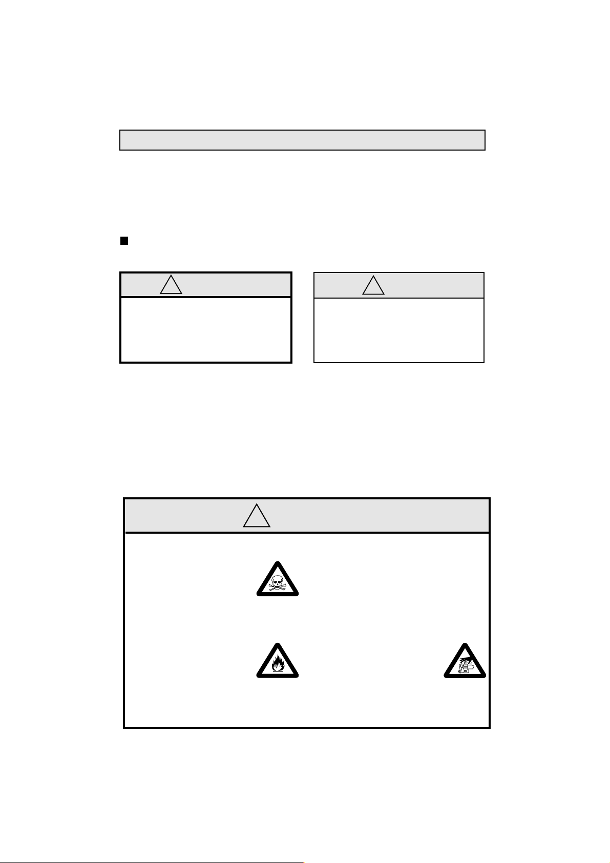
WARNINGS
!
These cover events which
might involve serious (in
extreme circumstances, even
fatal) injury.
!
•
Model engine fuel is poisonous. Do not allow it to
come into contact with the
eyes or mouth. Always store
it in a clearly marked container and out of the reach
of children.
Model engine fuel is also
•
highly flammable. Keep it
away from an open flame,
excessive heat, sources of
sparks, or anything else
which might ignite it. Do not
smoke or allow anyone else
to smoke, near to it.
These cover the many other
possibilities, generally less obvious
sources of danger, but which, under
certain circumstances, may also
cause damage or injury.
2
WARNINGS
•
Never operate your engine in an enclosed space. Model engines, like
automobile engines, exhaust deadly
carbon-monoxide. Run your engine
only in an open area.
Model engines generate
•
considerable heat. Do not
touch any part of your
engine until it has cooled.
Contact with the muffler
(silencer), cylinder head
or exhaust header pipe, in
particular, may result in a
serious burn.
!
NOTES
3
Page 3

!
This engine is intended for model cars.
•
Do not attempt to use it for any other
purpose.
Mount the engine in your model
•
securely, following the manufacturers'
recommendations, using appropriate
screws and locknuts.
Install an effective silencer (muffler).
•
Frequent close exposure to a noisy
exhaust (especially in the case of the
more powerful highspeed engines)
may eventually impair your hearing
and such noise is also likely to cause
annoyance to others over a wide area.
NOTES
•
The wearing of safety glasses is also
strongly recommended.
Take care that the glowplug clip or
•
battery leads do not come into contact
with rotating parts. Also check that the
linkage to the throttle arm is secure.
For their safety, keep all onlookers
•
(especially small children) well back
(at least 20 feet or 6 meters) when
preparing your model for running.
4
!
Before starting the engine, always check
the tightness of all the screws and nuts
especially those of joint and movable
parts such as throttle arm. Missing
retightening the loose screws and nuts
often causes the parts breakage that is
capable of harming you.
•
To stop the engine, fully retard the
throttle stick and trim lever on the
trans-mitter, or, in an emergency, cut
off the fuel supply by pinching the fuel
delivery line from the tank.
NOTES
•
Warning! Immediately after a glowplugignition engine has been run and is still
warm, conditions sometimes exist
whereby it is just possible for the engine
to abruptly restart if it is rotated over
compression WITHOUT the glowplug
battery being reconnected.
5
Page 4
NOTES WHEN APPL YING
AN ELECTRIC STARTER
Do not over-prime. This could
cause hydraulic lock and damage
the engine on application of the
electric starter.
If over-primed, remove glowplug,
close needle-valve and apply
starter to pump out surplus fuel.
Cover the head with a rag to
prevent pumped out fuel coming
into your eyes.
6
INTRODUCTION
The FS-26S-C Ver.II is an overhead valve
four stroke cycle engine designed
expressly for 1/10 class R/C vehicles.
Newly designed 20P carburetor has a
bigger bore of 5mm for increased power.
For longer life of the engine, Super Air
Cleaner 102S is supplied as standard.
Note:
As delivered, the carburetor is not
installed on the engine.
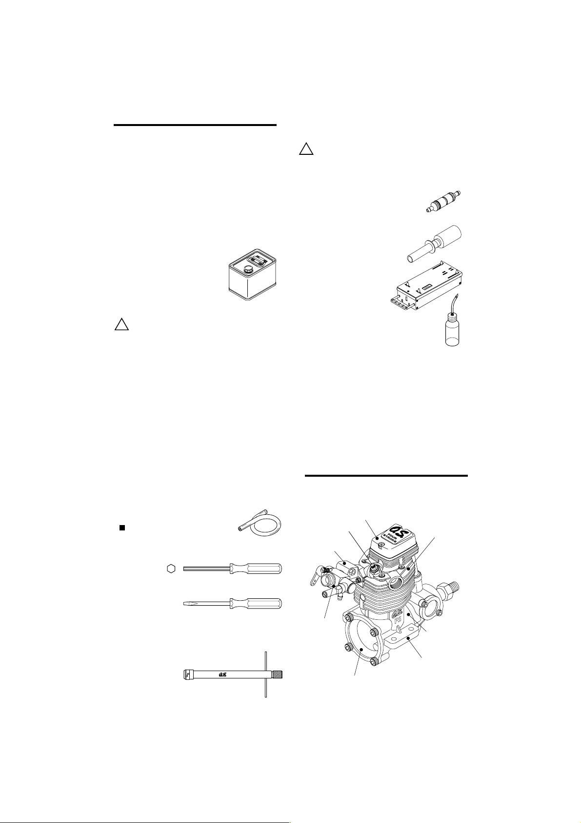
STANDARD ACCESSOIES
Glow Plug Type F
(included with the engine)
Super Air Cleaner
102S Assembly
Hyper Exhaust Gasket
Insulator
Intake Pipe Assembly
Carburetor Complete
(Type 20P)
7
Carburetor Retainer
Page 5
BEFORE STARTING
Tools, accessories, etc.The following items are
necessary for operating the engine.
FUEL
Generally, it is suggested that the user selects a fuel
that is commercially available for model two-stroke
engines and contains 10-30% nitromethane. As a
starting point, we recommend a fuel containing 20%
nitromethane, changing to a fuel containing more
nitro if necessary. When the brand of fuel is
changed, or the nitro content increased, it is
advisable to repeat the running-in procedure
referred to in the RUNNING-IN paragraphs. Please
note that with high-nitro fuels,
although power may be increased
for competition purposes, glowplug
elements do not last as long and
engine life will be shortened.
REMINDER!
Model engine fuel is poisonous. Do not allow
it to come into contact with the eyes or
!
mouth. Always store it in a clearly marked
container and out of the reach of children.
8
Model engine fuel is also highly flammable.
Keep it away from open flame, excessive
heat, sources of sparks, or anything else
!
which might ignite it. Do not smoke or allow
anyone else to smoke, near to it.
FUEL FILTER
To installed in the fuel line between
fuel tank and carburetor to prevent
dust coming into the carburetor.
GLOWPLUG IGNITER
Commercialy available handy
glowplug heater in which the
glowplug battery and battery
leads are integrated.
STARTER BOX
For starting the engine.
FUEL PUMP
For filling the fuel tank, a simple, polyethylene "squeeze" bottle, with a suitable spout, is required.
SILICONE FUEL LINE
Heatproof silicone tubing of approx. 5mm o.d.
and 2mm i.d. is required for the connection
between the fuel tank and engine.
TOOLS
HEX WRENCH
Necessary for engine installation.
1.5mm, 2mm, 2.5mm, 3mm
SCREWDRIVER
Necessary for carburetor adjustments.
No.1, No.2, etc
LONG SOCKET WRENCH WITH PLUG GRIP
Recommended for easy removal and
replacement of the angled and recessed
glowplug, the O.S.Long Socket Wrench
incorporates a special grip.
BASIC ENGINE PARTS
Rocker Cover
Glow Plug
Intake Pipe
Carburetor
Type 20P
Cover Plate
9
Cylinder Head
Crankcase
Beam Mount
Page 6

GLOWPLUG
The FS-26S-C Ver. is supplied with an O.S. Type F
glowplug, specially designed for O.S. four-stroke
engines.
The role of the glowplug
With a glowplug engine, ignition is initiated by the
application of a 1.5-volt power source. When the battery
is disconnected, the heat retained within the combustion
chamber remains sufficient to keep the plug filament
glowing, thereby continuing to keep the engine running.
Ignition timing is 'automatic' : under reduced load,
allowing higher rpm, the plug becomes hotter and,
appropriately, fires the fuel/air charge earlier;
conversely, at reduced rpm, the plug become cooler and
ignition is retarded.
Glowplug life
Particularly in the case of very high performance
engines,
glowplugs must be regarded as expendable
However, plug life can be extended and engine
performance maintained by careful use, i.e.:
Install a plug suitable for the engine.
Use fuel containing a moderate percentage of
nitromethane unless more is essential for racing
events.
Do not run the engine too lean and do not leave the
battery connected while adjusting the needle.
When to replace the glowplug
Apart from when actually burned out, a plug may
need to be replaced because it no longer delivers its
best performance, such as when:
Filament surface has roughened and turned white.
Filament coil has become distorted.
Foreign matter has adhered to filament or plug
body has corroded.
Engine tends to cut out when idling.
Starting qualities deteriorate.
10
AIR CLEANER TYPE 102S
It has a single filter element and is intended primarily
for circuit racing, where conditions are less damaging
than the very dusty, loose surf aces of off-road operation
for which the double-element Type 101 and 102 Air
Cleaners are recommended.
The lower height of the Super Air-Cleaner 102S also
facilitates easier installation in cars where available
space may be restricted.
INSTALLATION OF
AIR CLEANER
Carefully clean the carburetor,
removing any old adhesive or
sealant that may have been
previously used on the outside
of the air intake.
Press the air cleaner body firmly
over the carburetor air intake. Make sure that the
outer rim of the air intake engages the internal
annular groove in the air cleaner: failure to do so
may result in the air cleaner falling off.
Position the air cleaner correctly, so that it does not interfere
with the cylinder-head or obstruct the needle-valve.
11
INSTALLING THE FILTER ELEMENT
The element is already impregnated with a special
filter oil. As this oil is very sticky, take care, when
handling it, to prevent dust or dirt from adhering to the
element. If your fingers become contaminated, wash
them with soap and water.
During storage, the oil may
have become unevenly
dispersed through the element.
This will be indicated if the blue
colour of the element material
appears patchy. In this case,
place the element in a small
plastic bag and gently rub it
between finger and thumb to
redistribute the oil.
Insert beneath flange
REPLACEMENT OF ELEMENT
It is advisable to replace the filter element with a new
one after not more than one hour of running time.
Always remove contaminated elements carefully, to
ensure that dirt cannot enter the carburetor.
Page 7

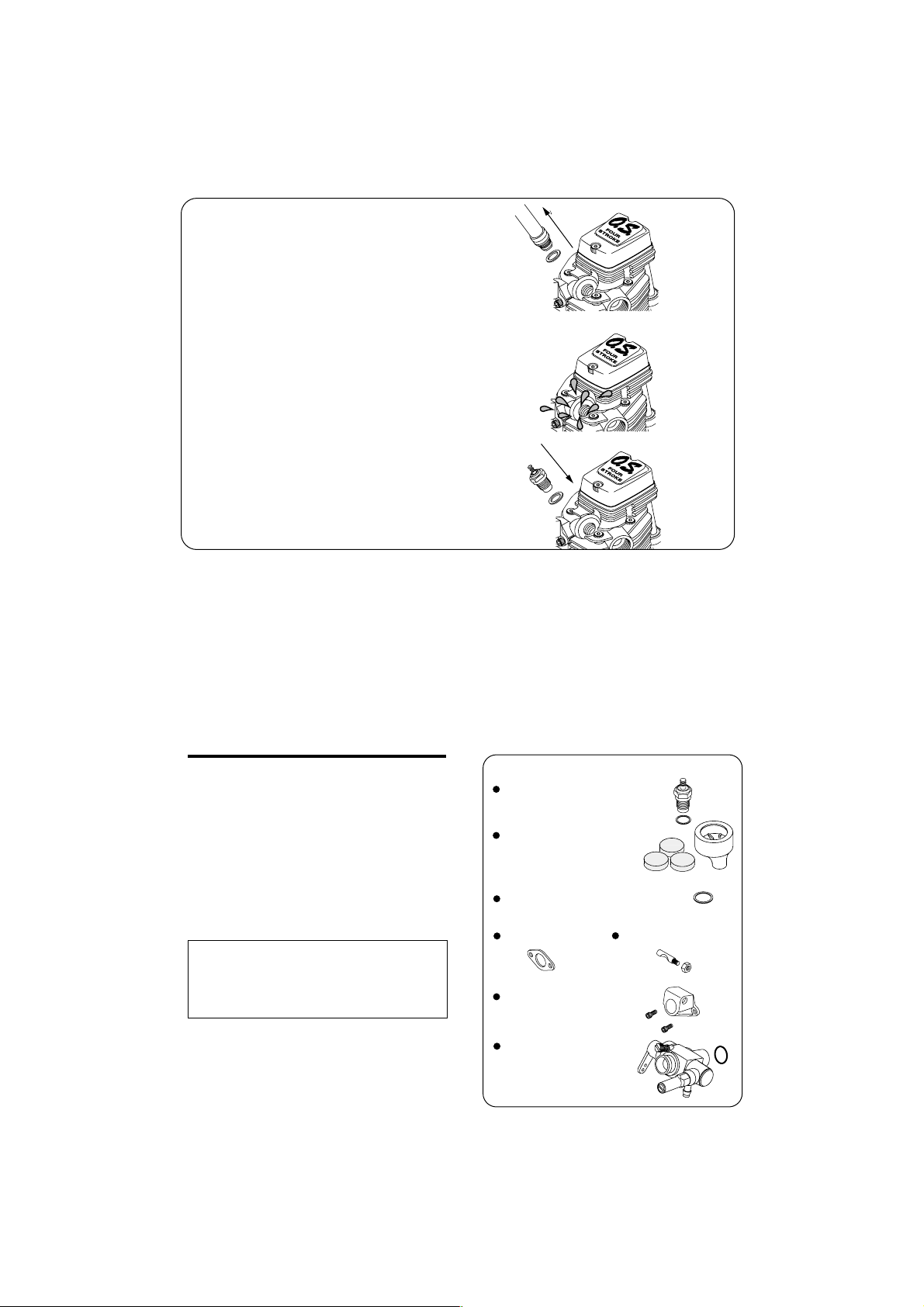
INSTALLATION OF THE CARBURETOR & HYPER EXHAUST GASKET
Install the insulator and intake manifold on
the cylinder head.
Install the carburetor retainer nut on the
intake manifold temporarily.
Install the carburetor gasket on the
carburetor.
Press the carburetor into the exhaust
manifold and fasten the lock nut gradually
until it stops.
Fasten the lock nut a further 60-90 degrees.
Do not fasten any further or the parts will be
distorted and/or damaged.
If you wish to change the fuel inlet position,
loosen the needle holder and set the inlet at
desired position, then fasten the needle
holder gradually until it stops and fasten a
further 45-60 degrees. Do not fasten any
further or the inlet will be distorted, which
results in fuel leaking.
Carburetor
Retainer
Note:
Installation procedure may vary according
to the car kit.
12
Intake Manifold
Fuel Inlet
Needle Holder
Insulator
Lock Nut
Carburetor Gasket
Hyper Exhaust Gasket
Insert Hyper exhaust gasket into the exhaust
port.
ENGINE INSTALLATION
Make sure that the vehicle's engine mounting
surfaces are level and in the same plane. Poor
installation may cause distortion of the
crankcase, bearings, etc., resulting in erratic
running and loss of performance. The
recommended screws for securing the engine
are 3mm or 4-40 steel Allen hexagon socket
type. If existing holes in the engine mount do not
align perfectly with engine mounting lugs,
enlarge them slightly with a needle-file so that
screws enter vertically. Avoid forcing the screws.
Secure with locknuts.
Chassis
⇒
Chamfer inside edges of bearers.
Chassis
13
Page 8

STARTING THE ENGINE & RUNNING-IN ('Breaking-in')
When starting the engine, lay the chassis
on a stand so that tiers may not be in
contact with the ground.
The somewhat violent changes of vehicle
attitude that occur in off-road running,
combined with the fact that, in buggy type
cars, the fuel tank is often located some way
from the carburetor, means that fuel ‘head’ at
the carburetor can vary and upset running.
Therefore, it is recommended that a muffler
pressurized fuel feed system be used.
Fuel Tank
Connect suitable length of
Silicone tubing between fuel
tank and silencer.
Silicone tubing
Silencer
In the interests of a long working life and high
performance, every internal-combustion engine
need to be “run-in” (or “breaking-in” as the
procedure is also known), while the engine is
installed in the car and run the car.
Fill the tank completely with fuel.
Fuel Pump
14
Fuel Tank
Temporarily remove the glowplug to check
that it glows bright red when energized.
Element glows when energized.
Pliers
Replace the plug when the
element does not glow or is
burnt out.
Glow Plug Igniter
NOTE
When checking the glowplug while energizing it, do not hold it by fingers but
!
use pliers. Do not come your face
close to the glowplug or get burned
with boiled fuel remaining in the coil.
Turn the needle-valve clockwise slowly until
it stops. This is the fully closed position.
Do not force to turn further.
Open
Close
Needle Valve
Open the Needle-Valve 2 turns from the fully
closed position.
Set the throttle-stop screw so that the
minimum throttle opening (idle setting) is
approximately 2mm.
●
Switch on the transmitter, followed by the
receiver. Close the throttle stick and open
the throttle trim lever to the idle setting.
15
約2.0mm
Page 9

Prime the carburetor by
pressing the fuel tank
Deliver fuel into the
carburetor.
primer until fuel reaches
the carburetor.
Fuel
Fuel tank side
Now connect glowplug battery lead to heat
the plug filament and start the engine.
Attention:
It is vitally important to set
the throttle at the correct
position before starting the
engine. If the engine is allowed
to run with the throttle too far open under ''no
load'' conditions (i.e. with the driving wheels
not in contact with
over-heat and may be seriously damaged.
the ground) it will rapidly
When the engine starts, first allow it to
operate in short runs at the very rich starting
settings, with the glowplug battery still
connected and the driving wheels clear of
the ground. The rich mixture will, under
these conditions, provide adequate
lubrication and cooling, indicated by profuse
smoke from the exhaust.
Next, disconnect the glowplug battery and
◆
try running the car on the track. If the engine
stalls, open the throttle fractionally, but try to
keep the engine running as rich as possible:
if it stops because of being excessively overrich, close the Needle-Valve 30˚ and try
again.
16
Run the car on the track until one tank of fuel
has been consumed, then close the NeedleValve 30˚ and run the car for another full
tank of fuel. Repeat this procedure until 1/2
gallon of fuel have been consumed, during
which time the throttle may be opened for
brief bursts of increased power.
The position of the needle-valve
Needle
The position of the
needle-valve where
highest speed of
the vehicle is
obtained.
when starting the engine.
Close the needle-valve
approx. 30° after
running the vehicle for
one full tank of fuel.
Repeat this procedure
several times.
Optimum needle-valve position
(10° to 20° opened from the position
where highest speed of the vehicle
is obtained.)
Now open the needle-valve 10°-20° from the
setting at which the highest straight line
speed is obtained. This slightly rich setting
should provide the optimum balance. Run the
car for about three more tanks of fuel to allow
fine-tuning of any final adjustments.
Re-adjust the throttle stop screw, if
neccessary, so that the car may not move at
idling.
Notes
Running-in the engine with excessive rich
setting means nothing but damage the
engine. Run-in the engine with adequate
running temperature so that the heat can be
conveyed to all the internal parts.
17
Page 10

Note:
Adjusting the carburetor with no load
condition means nothing but damage the
engine. Do not run the engine with no load.
In the event of any major working parts
(e.g. piston/cylinder liner assembly) being
replaced or the fuel changed, especially to
high nitro fuel, or silencer and gear ratio
and clutch timing changed, the complete
running-in should be repeated.
To stop the engine, close the throttle to
idling speed, then shut it off completely with
the trim lever on the transmitter. To cut off
the fuel supply, pinch the fuel delivery tube
to the carburetor.
Air Cleaner
Fuel
Gloves
Warning!
Do not touch rotating parts, engine and silencer when stopping the engine as they
become very hot, and contact with them
may result in a serious burn.
VALVE ADJUSTING
Valve clearances are correctly set before any
O.S. engine leaves the factory and, in normal
use, will seldom require adjustment. However,
if, after a considerable amount of running time,
a loss of power is detected, or if he engine has
been disassembled for repair, these
clearances should be checked and reset as
necessary.
For checking and adjusting the valve
clearances, a VALVE ADJUSTING TOOL KIT
is available as an optional accessory.
18
CARE & MAINTENANCE
At the end of each operating session, drain
the fuel tank, then energize the glowplug and
try to re-start the engine to burn off any fuel
that may remain inside. Repeat this
procedure until the engine fails to fire. Then
remove the glowplug and drain off any
residue while the engine is still warm.
Inject some corrosion-inhibiting after-run oil
and rotate the crankshaft to distribute oil to
the working parts. Do not inject such oil into
the carburettor, however, as it may cause
deterioration of the carburettor's O-ring seals.
Apply a little lubricating oil to the rocker shaft
and rocker arms.
Note!
These maintenance procedures will reduce
the risks of corrosion or starting difficulties
after a period of storage.
When cleaning the exterior of the engine,
use methanol or kerosene. Do not use
gasoline or any solvent that might damage
the silicone fuel tubing.
PARTS REPLACEMENT
Over a long period, depending on how well
your engine has been protected from the
ingress of dust and grit and other causes of
wear and tear, loss of performance may
eventually occur in the form of reduced
power, reluctant starting, unstable idling, etc.
Having checked that this is not due merely to
the need to readjust the valve clearances (for
which an O.S. Valve Adjustment Kit - Code
No. 72200060 - is available) inspection may
then reveal that the replacement of some
parts may be called for.
Contact the O.S. distributor in your country
for parts or full service. See pages 25 & 26 of
this booklet for details of parts.
19
Page 11

TROUBLE SHOOTING
Symptom
Engine fails to fire.
Cause
Fuel tank is empty.
Fuel not reaching the engine.
Glowplug element is burnt out.
Glowplug battery discharged
Clogged fuel filter
Air cleaner and silencer inside is dirty.
Over priming Remove glowplug and pump excess fuel.
Fill the tank with fuel and repeat
Priming procedure.
Replace glowplug.
Recharge or replace the battery.
Clean or replace fuel filter.
Replace cleaner element and clean inside silencer.
Corrective action
Fuel tubing is disconnected.
Fuel tubing is kinked, split or has a hole.
Incorrect servo linkage
Reverse rotating direction of starter box.
Symptom
Engine fires intermittently but does not run.
Cause
Insufficient fuel in the tank. Fill the tank with fuel.
Deteriorated glowplug
Clogged fuel filter
Air cleaner and silencer inside is dirty.
Connect fuel tubing securely.
Check the tubing carefully and replace if necessary.
Re-linkage after setting servo at neutral.
Mare sure it rotates counter clockwise seen
from crankshaft side.
20
Replace glowplug.
Clean or replace fuel filter.
Replace cleaner element and clean inside silencer.
Corrective action
Engine overheated
Incorrect clutch release
Too immediately disconnecting plug battery.
Fuel in the tank extremely bubbled
Wait until engine is cooled.
Adjust the tension of clutch spring.
Do not disconnect plug battery and wait until
r.p.m. become stable.
Fit O rings to the tank screws to
prevent bubbles.
21
Page 12

Symptom
Unstable idle
Cause
Corrective action
Unsuitable glowplug
Unsuitable fuel
Silencer is disconnected or has play
Symptom
Not reaching expected peak r.p.m.
Cause
Insufficient warming up or running-in.
Silencer or manifold is not securely connected
or disconnected.
Fuel tubing from tank to is split or broken.
Use suggested glowplug in the instructions.
Do not use extremely high nitro or low oil fuel.
Install silencer securely.
Corrective action
Set the needle only after warming up.
Complete running-in.
Check the connections and secure them.
Replace the tubing.
22
Symptom
Poor response
Cause
Deteriorated glowplug
Incorrect carburetor settings
Incorrect setting of transmitter Exponential function.
Symptom
Poor r.p.m. drop
Cause
Too much throttle opening at idle.
Incorrect carburetor fitting
Corrective action
Replace glowplug.
Readjust low r.p.m. range with needle Valve
and Throttle Stop Screw.
Check the transmitter setting.
Corrective action
Close Throttle Stop Screw to adequate position
to lower idle r.p.m.
Fit carburetor securely.
23
Page 13

ENGINE EXPLODED VIEW
C.M2.6x12
4
11
C.M2.6x8
24
19
C.M2.6x7
Type of screw C…Cap Screw M…Oval Fillister-Head Screw
*
10
0.2mm
12
20
20-1
21
F…Flat Head Screw N…Round Head Screw S…Set Screw
4-2
4-1
9
M3.5
13
16
22
C.M3x10
14
15
17
18
2
C.M2.6x18
3-1
3-2
5-4
5-3
5-2
8
5-1
29
24
23
27-2
30
25
26
27-1
27-2
28
3
5
6
C.M2.6x7
27
ENGINE PARTS LIST
No.
Code No.
1
44113000
2
43004200
3
45761400
3-1
45761410
3-2
45761600
4
45761000
4-1
45761100
4-2
45761200
5
45760020
5-1
45760110
5-2
45760210
5-3
45060309
5-4
46160400
6
44104100
7
44104020
8
45169100
9
7
25
1
21381950
10
45269400
11
21481700
12
45282000
13
22714100
14
44103400
15
44103200
16
22706000
17
45705000
18
44103100
19
45707010
20
44102010
20-1
45702100
21
22830000
22
44101010
23
45762100
24
45762010
25
45701110
26
44166000
27
44166100
27-1
44166110
27-2
24881824
28
45264000
29
45231000
30
23210007
71615009
72403202
72403212
72403120
The specifications are subject to alteration for improvement without notice.
Screw Set
Rocker Cover
Rocker Support Assembly
Rocker Support
Rocker Arm Retainer (2pcs.)
Rocker Arm Assembly (1pair)
Rocker Arm (1pc.)
Tappet Adjusting Screw
Valve Assembly (1pair)
Valve (1pc.)
Valve Spring (1pc.)
Valve Spring Seat (1pc.)
Valve Spring Retainer (2pcs.)
Cylinder Head (W/Gasket)
Cylinder Head Assembly (W/Gasket and Valve Assembly)
Hyper Exhaust Gasket (2pcs.)
Insulator
Intake Pipe Assembly
Carburetpr Retainer
Carburetor Complete (Type 20P)
Cylinder Head Gasket
Piston Ring
Piston
Piston Pin
Connecting Rod
Cylinder Liner
Cover Plate
Crankshaft
Crankshaft Spacer
Crankshaft Ball Bearing (Rear)
Crankcase
Thrust Ball (2pcs.)
Camshaft
Cam Cover
Push Rod (2pcs.)
Push Rod Cover Assembly (2pcs.)
Push Rod Cover (1pc.)
Push Rod Cover "O" Ring (2pcs.)
Cam Follower (2pcs.)
Crankshaft Ball Bearing (Front)
Propeller Nut
Glow Plug Type F
Super Air Cleaner 102S (W/3 filter elements)
102S Cleaner Body
101,102 Filter Element (6pcs.)
Description
Page 14
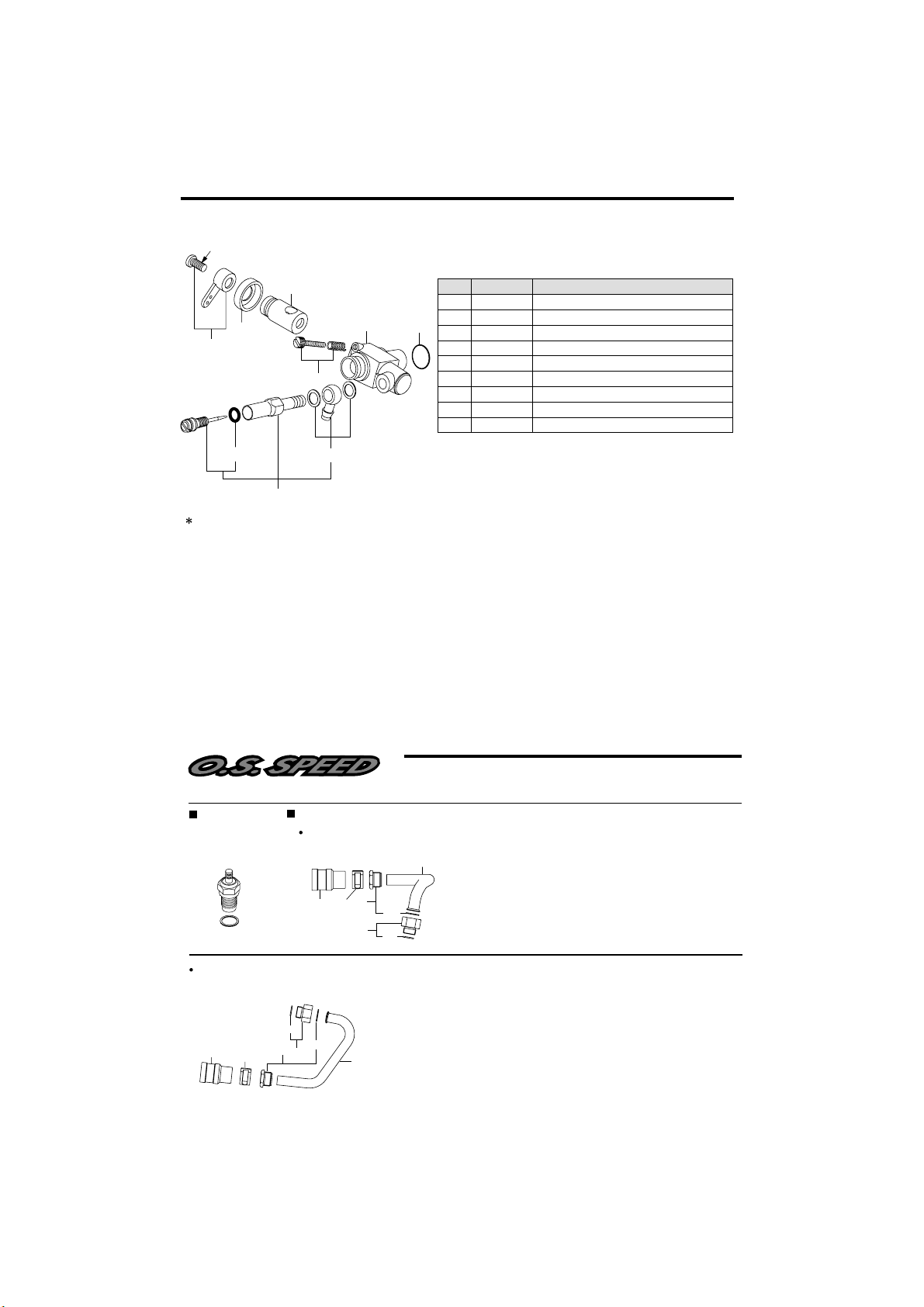
CARBURETOR EXPLODED VIEW & PARTS LIST
N.+M3x6
3
2
1
4
6-1
6
Type of screw
C...Cap Screw M...Oval Fillister-Head Screw
F...Flat Head Screw N...Round Head Screw S...Set Screw
5
6-2
No.
Code No.
22081408
1
21283210
2
7
45282200
3
22681310
4
45282100
5
21285901
6
27881820
6-1
21881950
6-2
22615000
7
The specifications are subject to alteration for improvement without notice.
Throttle Lever Assembly
Carburetor Dust Cover
Carburettor Rotor
Throttle Stop Screw
Carburettor Body
Needle-valve Assembly
"O" Ring (2pcs.)
Universal Nipple No.14 Assembly
Carburettor Rubber Gasket
Description
26
RACING ENGINE PARTS
GLOWPLUG
Type F
(71615009)
For Kyosho Spider
(44126010)
4
5
HYPER EXHAUST SET
For Kyosho Super 10
(44126000)
5
4
3-1
2-1
2
3
1
O.S. GENUINE PARTS & ACCESSORIES
2
3
2-1
3-1
1
(44126110)
(45169200)
2
2-1
(45169210)
(44126200)
3
(45169100)
3-1
(44126300)
4
(44126400)
5
1
(44126100)
(45169200)
2
1
2-1
(45169210)
(44126200)
3
(45169100)
3-1
(44126300)
4
(44126400)
5
Hyper Exhaust Pipe
Exhaust Pipe Lock Nut
Exhaust Gasket (2pcs.)
Exhaust Adaptor
Hyper Exhaust Gasket (2pcs.)
Pipe Joint
Clamp
27
Hyper Exhaust Pipe
Exhaust Pipe Lock Nut
Exhaust Gasket (2pcs.)
Exhaust Adaptor
Hyper Exhaust Gasket (2pcs.)
Pipe Joint
Clamp
Page 15

RACING ENGINE PARTS
O.S. GENUINE PARTS & ACCESSORIES
SUPER JOINT TUBE 15
(72103310)
VALVE ADJUSTING
KIT
(72200060)
F-2000 4C CAR SILENCER
(44125100)
LONG SOCKET WRENCH
WITH PLUG GRIP
(71521000)
The specifications are subject to alteration for improvement without notice.
28
FS-26S-C ENGINE MOUNT
For Kyosho V-oneR, S
(72404400)
For HPI Nitro Series
(72404500)
CAP SCREW SET
(79871020)
M2.6x7
(79871025)
M2.6x8
(79871040)
M2.6x12
(79871055)
M2.6x18
(10pcs. / set)
THREE VIEW DRAWING
SPECIFICATIONS
Displacement
■
Bore
■
Stroke
■
■
Practical R.P.M.
■
Power output
■
Weight
4.41cc (0.270cu.in.)
18.5mm (0.728in.)
16.4mm (0.646in.)
2,000-22,000 r.p.m.
0.5ps / 17,000 r.p.m.
242.5g (8.56oz.)
70.9
14.5
36
43
4- 3.3
UNF1/4-28
14.6 39.8 18
29
14
Dimensions (mm)
Page 16

MEMO
30
E
R
C
P
I
S
I
Y
O
T
I
L
A
U
Q
D
E
L
L
A
U
Q
E
N
U
E
S
T
A
B
L
I
S
H
I
N
G
T
H
E
S
S
T
D
A
R
N
A
D
C
Copyright 2005 by O.S.Engines Mfg. Co., Ltd. All rights reserved. Printed in Japan.
N
&
P
E
R
F
O
R
M
A
N
C
E
E
C
N
E
L
L
E
C
X
E
F
O
6-15 3-Chome Imagawa Higashisumiyoshi-ku
Osaka 546-0003, Japan
URL : http://www.os-engines.co.jp
TEL. (06)6702-0225
FAX. (06)6704-2722
60091670 030500
 Loading...