

Page 1
It is of vital importance, before attempting to
operate your engine, to read the general
'SAFETY INSTRUCTIONS AND WARNINGS'
section on pages 2-4 of this booklet and to
strictly adhere to the advice contained therein.
Also, please study the entire contents of this
instruction manual, so as to familiarize
yourself with the controls and other features of
the engine.
Keep these instructions in a safe place so that
you may readily refer to them whenever
necessary.
It is suggested that any instructions supplied
with the aircraft, radio control equipment, etc.,
are accessible for checking at the same time.
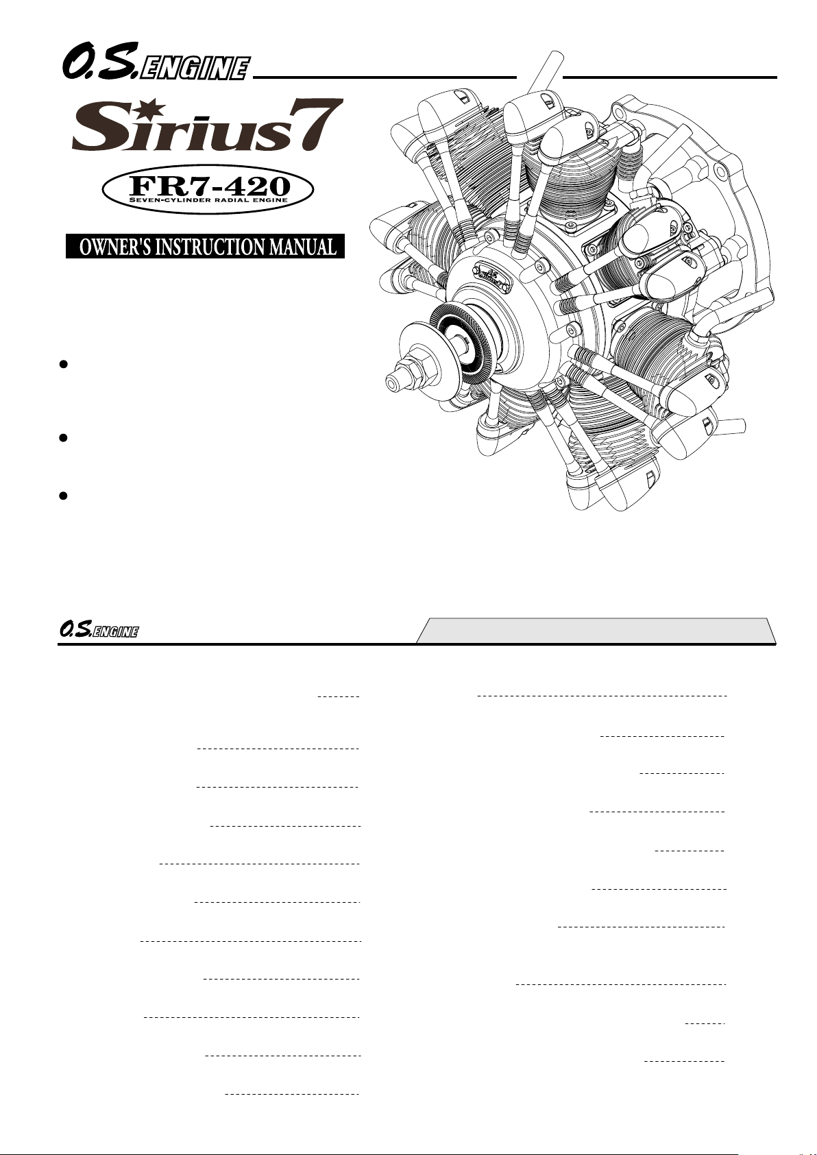
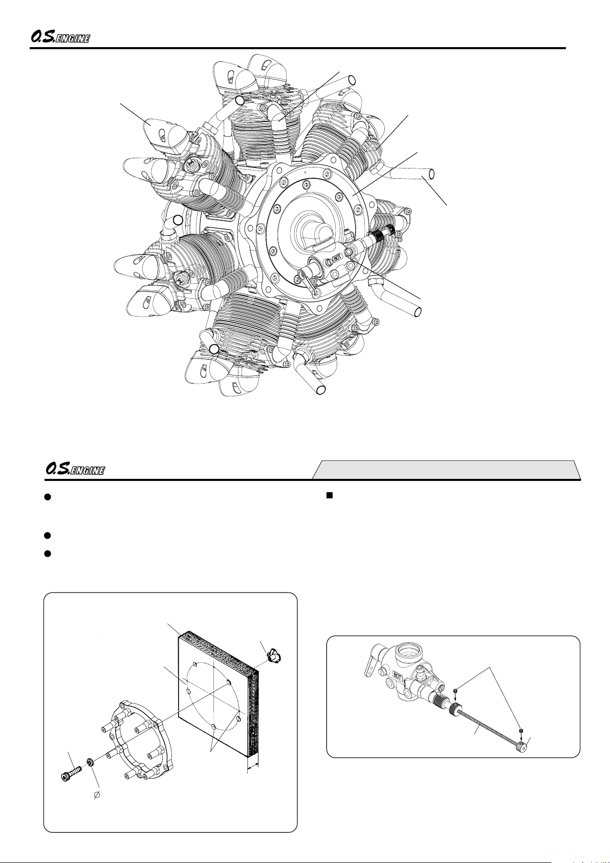
Seven-cylinder radial
overhead-valve four-stroke engine
1
SAFETY INSTRUCTIONS AND
WARNINGS ABOUT YOUR O.S. ENGINE
NOTES WHEN APPLYING AN
ELECTRIC STARTER
ABOUT THE ENGINE
ENGINE PARTS NAME
INSTALLATION
FUEL TANK & LINES
GLOWPLUG
MIXTURE CONTROLS
PROPELLER
GLOWPLUG HEATING
FUEL AND LUBRICATION
CONTENTS
STARTING
RUNNING-IN ("Breaking-in")
THROTTLE VALVE ADJUSTMENT
FLIGHT & MAINTENANCE
VALVE CLEARANCE ADJUSTMENT
ENGINE EXPLODED VIEW
ENGINE PARTS LIST
CARBURETOR EXPLODED VIEW
& PARTS LIST
O.S. GENUINE PARTS & ACCESSORIES
ENGINE THREE VIEW DRAWINGS
2-4
5
6
7-8
9-10
11
12
13
14-15
16
17-18
19-21
22
23-25
26-27
28-29
30
31
32
33
34
Page 2
2
Remember that your engine is not a " toy ", but a highly
efficient internal-combustion machine whose power is
capable of harming you, or others, if it is misused or
abused. As owner, you, alone, are responsible for the safe
operation of your engine, so act with discretion and care at
all times.
If at some future date, your O.S. engine is acquired by
another person, we would respectfully request that these
instructions are also passed on to its new owner.
WARNINGS
These cover events which might involve serious ( in
extreme circumstances, even fatal ) injury.
NOTES
These cover the many other possibilities, generally less
obvious sources of danger, but which, under certain
circumstances, may also cause damage or injury.
SAFETY INSTRUCTIONS AND
WARNINGS ABOUT YOUR
O.S. ENGINE
The advice which follows is grouped under two
headings according to the degree of damage or danger
which might arise through misuse or neglect.
WARNINGS
Never touch, or allow any object to come into
contact with, the rotating propeller and do not
crouch over the engine when it is running.
A weakened or loose propeller may disintegrate or be thrown
off and, since propeller tip speeds with powerful engines may
exceed 600 feet(180 metres) per second, it will be understood
that such a failure could result in serious injury, (see 'NOTES'
section relating to propeller safety).
Model engine fuel is poisonous. Do not allow it to
come into contact with the eyes or mouth. Always
store it in a clearly marked container and out of
the reach of children.
Model engine fuel is also highly flammable. Keep it
away from an open flame, excessive heat, sources
of sparks, or anything else which might ignite it.
Do not smoke or allow anyone else to smoke, near
to it.
Never operate your engine in an enclosed space. Model
engines, like automobile engines, exhaust deadly carbonmonoxide. Run your engine only in an open area.
Model engines generate considerable heat. Do
not touch any part of your engine until it has
coole d. Contact with the mu ffler(silencer),
cylinder head or exhaust header pipe, in
particular, may result in a serious burn.
3
NOTES
This engine was designed for model aircraft. Do not attempt to use it for any other purpose.
Mount the engine in your model securely, following the manufacturers' recommendations, using appropriate
screws and locknuts.
If you remove the glowplug from the engine and check its condition by connecting the battery leads to it, do not hold
the plug with bare fingers.Use an appropriate tool or a folded piece of cloth.
Install a top-quality propeller of the diameter and pitch specified for the engine and aircraft. Locate the propeller on
the shaft so that the curved face of the blades faces forward-i.e. in the direction of flight. Firmly tighten the propeller
nut, using the correct size wrench.
Always check the tightness of the propeller nut and retighten it, if necessary, before restarting the engine,
particularly in the case of four-stroke-cycle engines. If a safety locknut assembly is provided with your engine,
always use it. This will prevent the propeller from flying off in the event of a "backfire", even if it loosens. Also,
check the tightness of all the screws and nuts before restarting the engine.
If you install a spinner, make sure that it is a precision made product and that the slots for the propeller blades
do not cut into the blade roots and weaken them.
Discard any propeller which has become split, cracked, nicked or otherwise rendered unsafe. Never attempt to
repair such a propeller: destroy it. Do not modify a propeller in any way, unless you are highly experienced in tuning
propellers for specialized competition work such as pylon-racing.
Use an electric starter for this engine. The wearing of safety glasses is also strongly recommended.
Page 3
4
Take care that the glow plug clip or battery leads do not come into contact with the propeller.
Also check the linkage to the throttle arm. A disconnected linkage could also foul the propeller.
After starting the engine, carry out any needle-valve readjustments from a safe position behind the rotating
propeller. Stop the engine before attempting to make other adjustments to the carburetor.
Adjust the throttle linkage so that the engine stops when the throttle stick and trim lever on the transmitter are fully
retarded. Alternatively, the engine may be stopped by cutting off the fuel supply. Never try to stop the engine
physically.
Take care that loose clothing (ties, shirt sleeves, scarves, etc.) do not come into contact with the propeller.
Do not carry loose objects (such as pencils, screwdrivers, etc.) in a shirt pocket from where they could fall through
the propeller arc.
Do not start your engine in an area containing loose gravel or sand. The propeller may throw such material in your
face and eyes and cause injury.
For their safety, keep all onlookers (especially small children) well back (at least 20 feet or 6 meters) when preparing
your model for flight. If you have to carry the model to the take-off point with the engine running, be especially
cautious. Keep the propeller pointed away from you and walk well clear of spectators.
Warning! Immediately after a glowplug-ignition engine has been run and is still warm, conditions sometimes exist
whereby it is just possible for the engine to abruptly restart if the propeller is casually flipped over compression
WITHOUT the glowplug battery being reconnected. Remember this if you wish to avoid the risk of a painfully rapped
knuckle!
NOTES
5
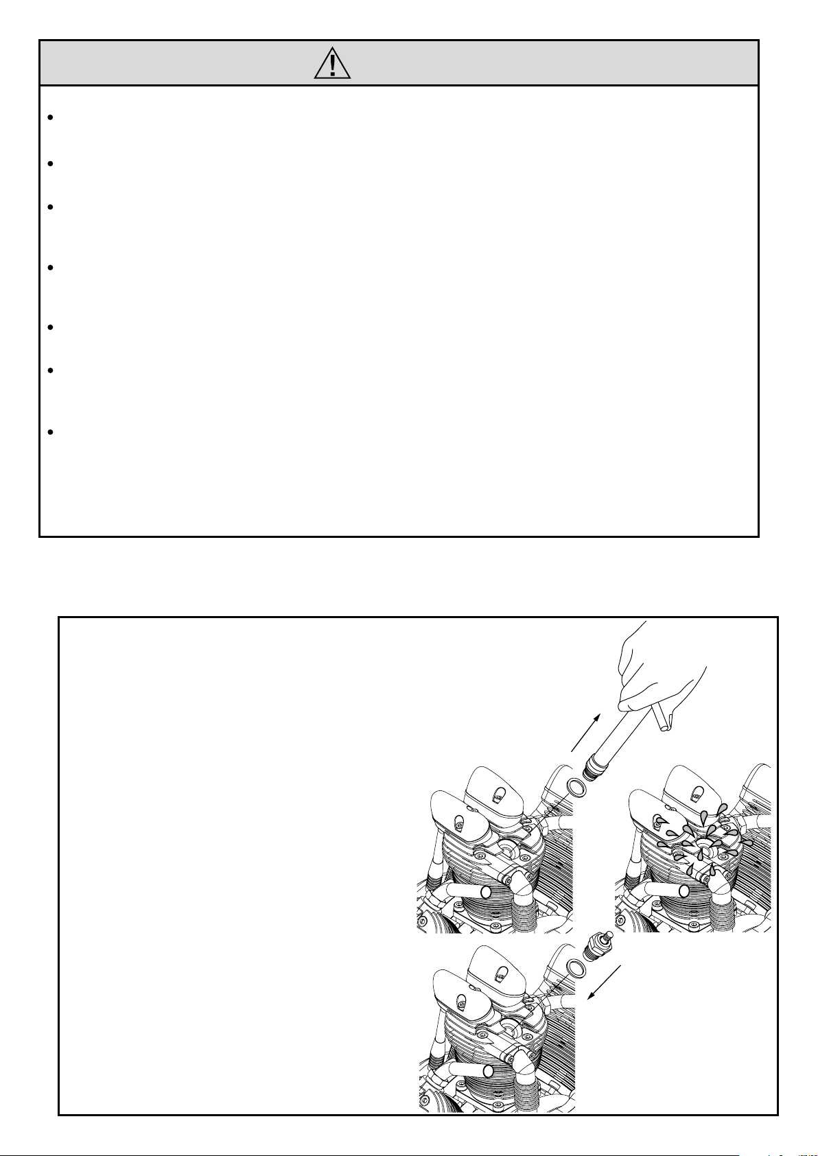
NOTES WHEN APPLYING
AN ELECTRIC STARTER
Do not over-prime. This could
cause a hydraulic lock and
damage the engine on application
of the electric starter.
If over-primed, remove glowplug,
close needle-valve and apply
starter to pump out surplus fuel.
Cover the head with a rag to
prevent pumped out fuel from
getting into your eyes.
Page 4
6
The FR7-420 (Sirius7) is a seven-cylinder radial
overhead-valve four-stroke-cycle engine of 70cc
displacement. The engine maintains the same
features of stress free starting, super smooth idling
and high torque power which is always the hallmark
of O.S. large size multi-cylinder engines. With its
finely detailed design and outstanding scale
appearance and sound, the engine's quality is
second to none.
ABOUT THE ENGINE
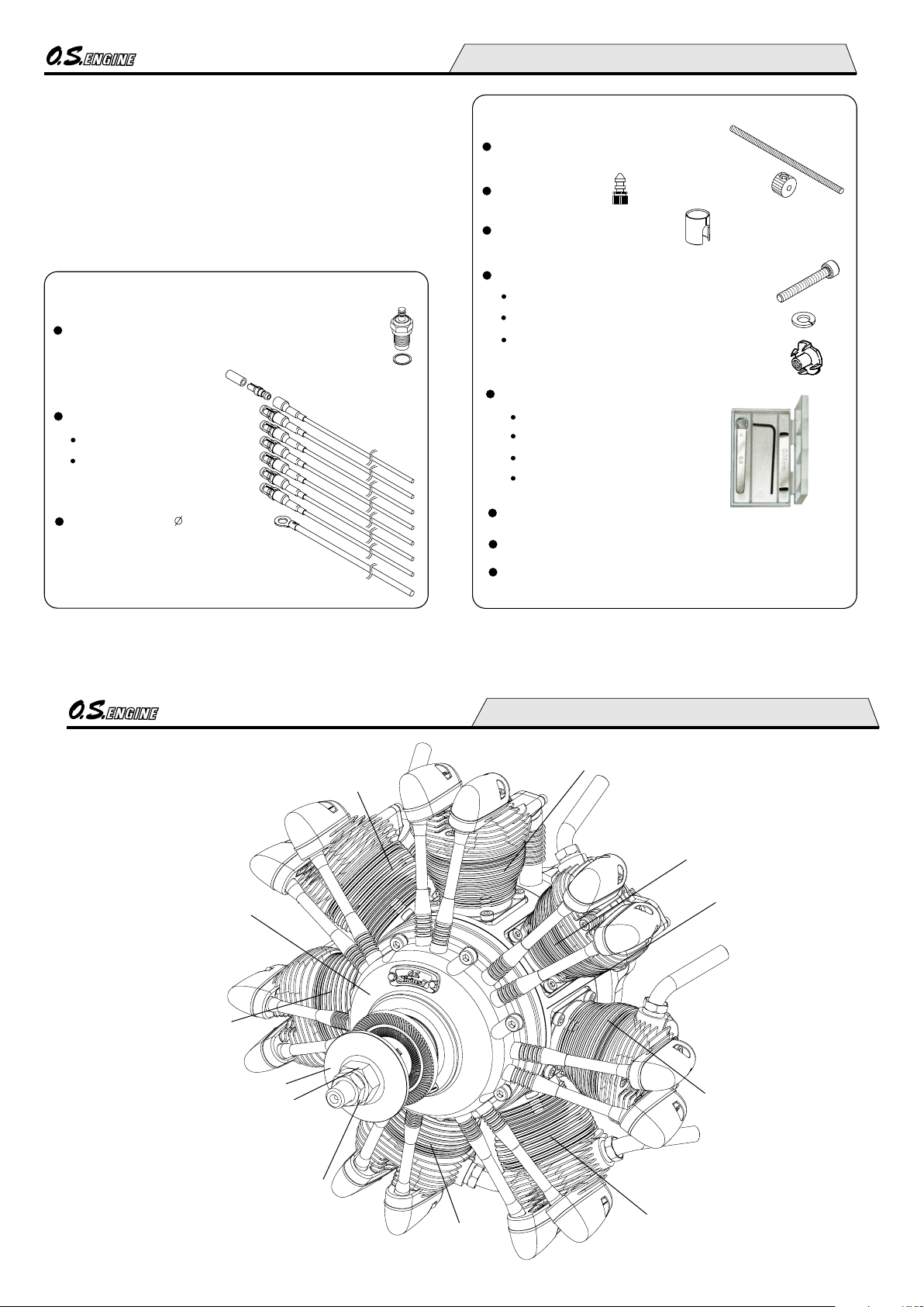
STANDARD ACCESSORIES
Glow Plug Type F (installed on the engine)
Valve adjusting tool kit
Feeler gauge 0.04mm
Feeler gauge 0.1mm
Hex. key 1.5mm
Wrench 5mm
Plug Cable Set
Plug Cable
Plug Terminal (7pcs.)
(7pcs.)
(w/silicone tube)
Radial Mount Retaining Screw Set
Engine mounting screws (M5X25)
Lock washers (ø5)
Blind nuts (M5)
(5pcs.)
(5pcs.)
(5pcs.)
Lead for ground 5 (1pc.)
Needle-Valve Extension Cable Set
STANDARD ACCESSORIES
Drain Plug
Carburetor Insert
Decal
Instruction Manual
Aluminum Case
7
ENGINE PARTS NAME
Lock Nut
Propeller Washer
Crankcase
Propeller Nut
No.1 Cylinder
No.2 Cylinder
No.3 Cylinder
No.4 Cylinder
Front Housing
No.5 Cylinder
No.7 Cylinder
No.6 Cylinder
Page 5
8
Rocker Cover
Cylinder Head
Exhaust Pipe
Intake Pipe
Back Plate
Carburetor Type 80T
9
Needle-valve extension
It is essential that the firewall is strong and rigid (e.g. at
least 15mm thick) and firmly integrated with the structure of
the aircraft.
INSTALLATION
M5 Blind nut
Firewall
M5x25 screw
5 Lock washer
At least 15mm (0.6")
rigid hard wood
It is suggested to install the engine upright.
Set-screw
Knob
Cable
It is suggested to use Lock Washers (available as an
optional extra) with engine installing screws or apply
LOCTITE to the screws to prevent them from loosening.
The needle-valve supplied with this engine is designed to
incorporate an extension so that, when the engine is
enclosed within the fuselage, the needle-valve may be
adjusted from the outside. For this purpose, a Needle Valve
Extension Cable Set is supplied with the engine.
If a longer extension is reguired, cut a commercially
available rod to the required length, bend one end to an L
shape, insert it into needle's center hole and secure it by
tightening the set-screw in the needle-valve knob with
1.5mm Allen key.
Needle Valve Extension Cable Set
Center mark
122mm (4-13/16") dia. circle
Note:
Carburetor installing direction cannot be changed and
the needle direction cannot be changed. Avoid the place
near the exhaust pipe when fixing the extension cable.
Page 6
10
Exhaust pipe
Exhaust pipe becomes very hot while running and right
after running, make sure it does not touch the model and
never allow hand and body to touch it.
Check the tightness of locknuts while the engine is warm
after the first flight.
10mm wrench
Loosen
Tighten
Lock nut
Exhaust pipe
Carburetor cleanliness
It is recommended that the fuel is passed through a filter
when the tank is filled and that a good in-line filter is
installed between the fuel tank and carburetor.
Occasionally remove the needle-valve holder from the
carburetor and rinse out the locations shown below with
methanol or fuel. Be careful not to lose the gasket when
removing the needle-valve holder from the carburetor.
Squeeze bottle
Dirt and foreign matter
mostly accumulate here.
Dirt and foreign matter
mostly accumulate here.
Needle-valve holder
11
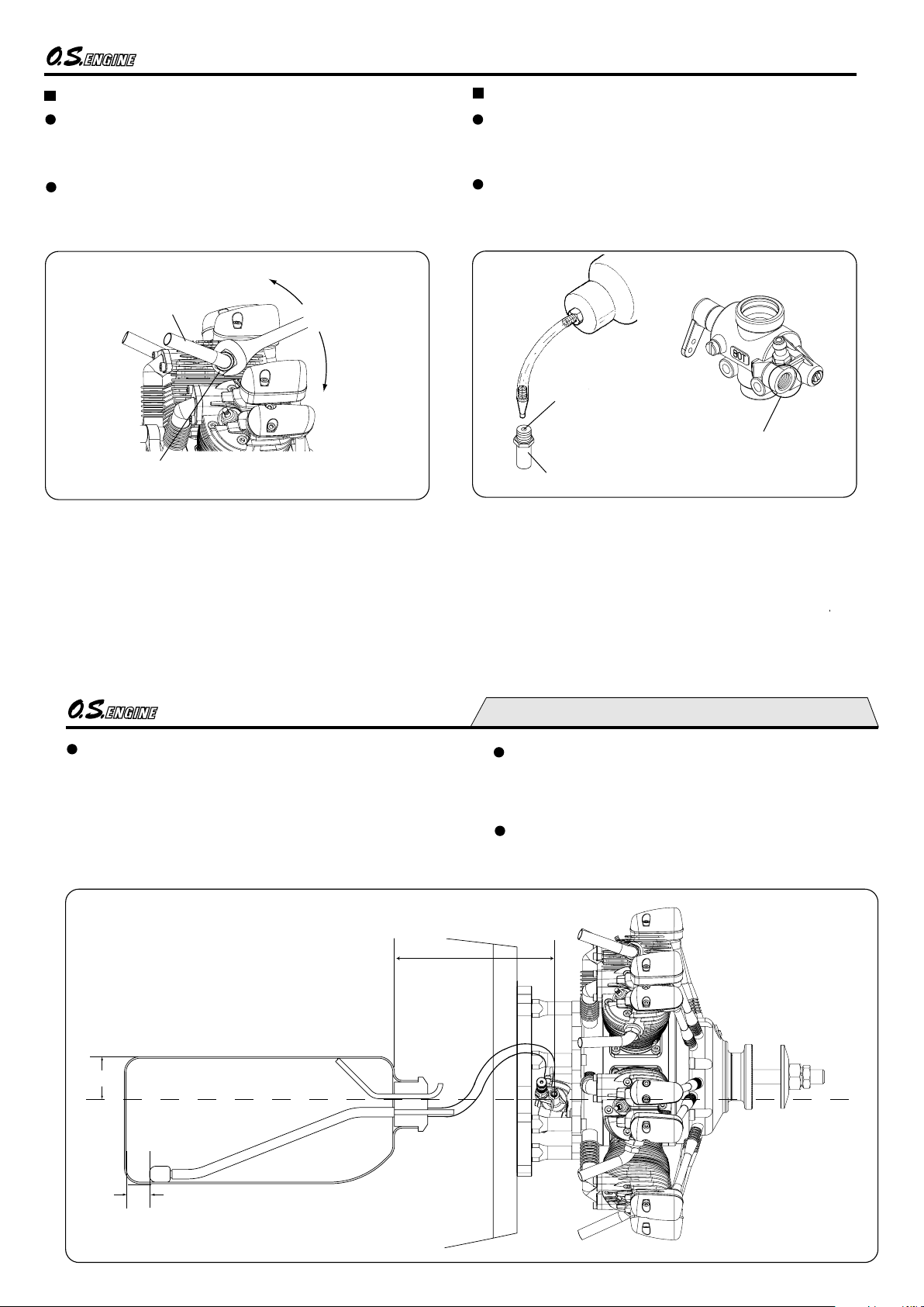
FUEL TANK & LINES
Make sure that the tank is well rinsed out with methanol or
glow fuel before installation and that the pickup weight is
well clear of the bottom of the tank when held vertically.
A 700cc tank will allow approx. 10 minutes medium speed
flight.
Locate the fuel tank as close as possible to the
carburetor, or the fuel level difference will
affect the engine running when the model is
upright or inverted.
Set the fuel tank position so that the carburetor
center line is 1/3 lower than from the tank top
when the model is placed horizontal.
Approx. 15mm
1/3
Be sure to follow the instructions concerning the
relationship between fuel tank and carburetor position, or
the expected stable idle running will not be obtained even
with adequate carburetor adjustment.
For plumbing, use heavy duty silicone tube of 2.5mm inner
dia and 5mm outer dia.
Page 7
12
GLOWPLUG
The role of the glowplug
Glowplug life
Particularly in the case of very high performance engines,
glowplugs must be regarded as expendable items. However,
plug life can be extended and engine performance maintained
by careful use, i.e.:
Install a plug suitable for the engine.
Use fuel containing a moderate percentage of
nitromethane.
Do not run the engine too lean and do not leave the
battery connected while adjusting the needle.
With a glowplug engine, ignition is initiated by the application
of a 1.5-volt power source. When the battery is disconnected,
the heat retained within the combustion chamber remains
sufficient to keep the plug filament glowing, thereby continuing
to keep the engine running. Ignition timing is 'automatic' : under
reduced load, allowing higher rpm, the plug becomes hotter
and, appropriately, fires the fuel/air charge earlier; conversely,
at reduced rpm, the plug become cooler and ignition is
retarded.
Apart from when actually burned out, a plug may need to be
replaced because it no longer delivers its best performance,
such as when:
When to replace the glowplug
Filament surface has roughened and turned white.
Filament coil has become distorted.
Foreign matter has adhered to filament or plug body has
corroded.
Engine tends to cut out when idling.
Starting qualities deteriorate.
Since the compatibility of the glowplug and
fuel may have a marked effect on
performance and reliability, it is suggested
to use the O.S. Type F plug when it is
necessary to replace. Carefully install plug
finger-tight, before final tightening with the
correct size plug wrench.
The engine is installed with the O.S. Type F plugs.
13
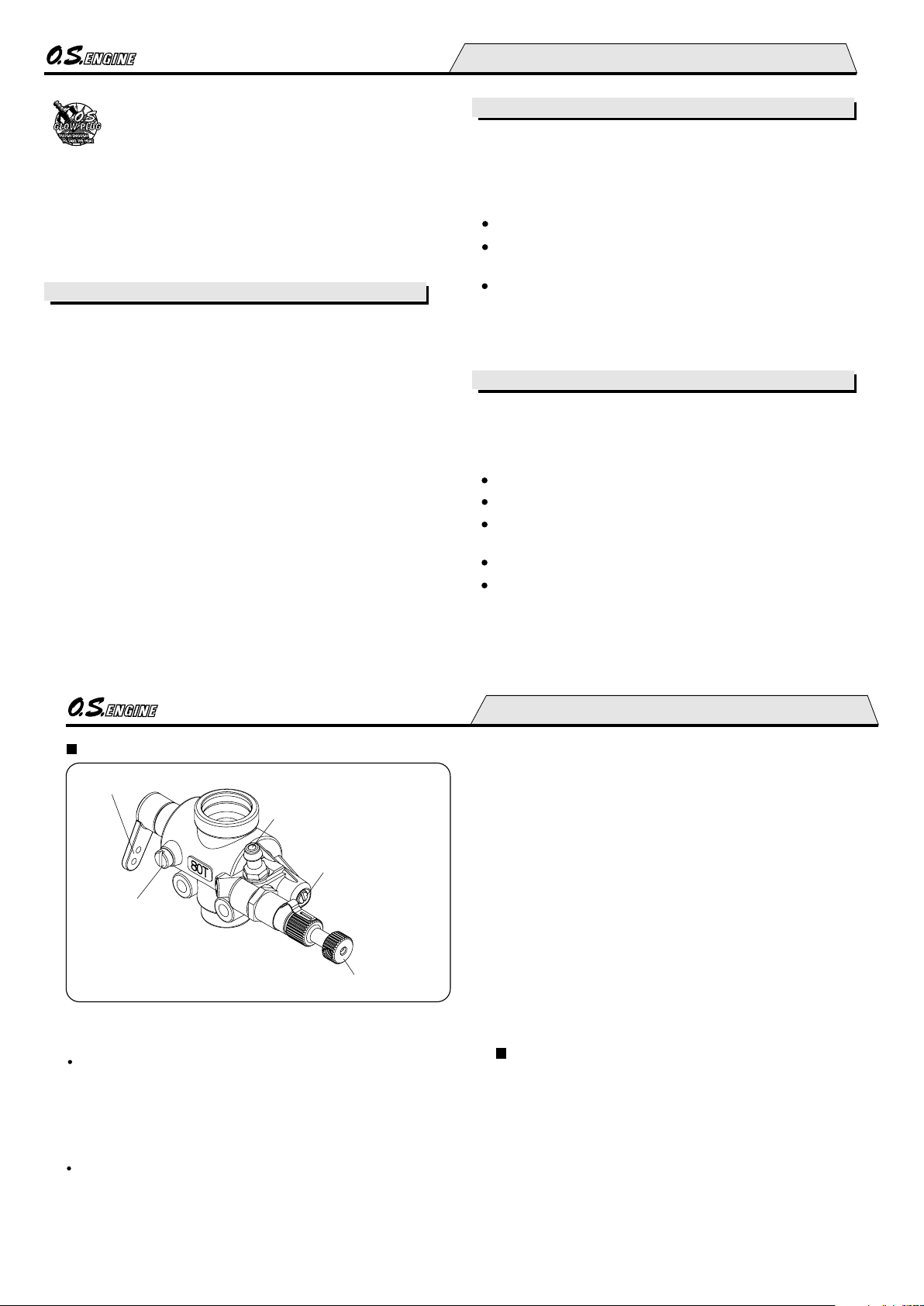
MIXTURE CONTROLS
The Needle Valve
When set to produce maximum power at full throttle, this
establishes the basic fuel/air mixture strength. The correct
mixture is then maintained by the carburetor's built-in
automatic mixture control system to cover the engine's
requirements at reduced throttle settings.
The Mixture Control Valve
This meters fuel flow at part-throttle and idling speeds to
ensure reliable operation as the throttle is opened and
closed. The Mixture Control Valve is factory set for the
approximate best result. First run the engine as received and
readjust the Mixture Control Screw only if necessary.
Two mixture controls are provided on this
Carburetor.
Needle Valve
Mixture Control Valve
The carburetor Mixture Control Valve is set at basic position (
a little on the rich side) at the factory. However, minor
readjustment will be required for a fuel used, atmospheric
conditions and a model. When a good result is not obtained
with the factory setting, readjust it according to the MIXTURE
CONTROL VALVE ADJUSTMENT section. Please note
during a running-in period flights should be made with a
slightly rich needle setting. Therefore, during a running-in
period proper carburetor responses will not be obtained.
Adjust it for optimum position after the running-in is
completed.
THROTTLE LINKAGE
Before connecting the throttle to its servo, make sure that
the throttle arm and linkage safely clear any adjacent part
of the airframe structure, etc., as the throttle is opened and
closed. Connect the linkage so that the throttle is fully
closed when the transmitter throttle stick and its trim lever
are at their lowest settings and fully open when the throttle
stick is in its fully-open position. Carefully align the
appropriate holes in the throttle arm and servo horn so that
they move symmetrically and smoothly through their full
travel.
Throttle Lever
Fuel Inlet
Rotor Guide Screw
CARBURETOR 80T PARTS NAMES
Page 8

14
22x10-12, 23x8-12,
24x8-12, 26x8
PROPELLER
The choice of propeller depends on the design and weight of
the aircraft and on the type of flying in which you will be
engaged. Determine the best size and type after practical
experimentation. As a starting point, refer to the props listed in
the accompanying table. Slightly larger, or even slightly
smaller, props than those shown in the table may be used, but
remember that propeller noise will increase if blade tip velocity
is raised, due to higher rpm or if a larger-diameter / lower-pitch
prop is used.
Make sure that the propeller is well balanced. An
unbalanced propeller and / or spinner can cause serious
vibration which may weaken parts of the airframe or
affect the safety of the radio-control system.
DO NOT forget the WARNINGS and NOTES on propeller
and spinner safety given on pages 2,3 and 4.
Warning:
Type
Size (DxP
)
Sport / Scale
1.
PROPELLER & SPINNER ATTACHMENT
There is a risk, particularly with powerful four-stroke engines,
of the propeller flying off if the prop nut loosens due to
detonation ("knocking") in the combustion chamber when the
engine is operated too lean, or under an excessively heavy
load.
Obviously, this can be very hazardous. To eliminate such
dangers, the O.S. Safety Locknut Assembly was devised.
Install this as follows:
To be equal
To be equal
Ream to 9.7mm dia.
Use a propeller that has a
hub of more than 40mm dia.
Ream the propeller shaft hole to 9.7mm bore with an
appropriate reamer, checking that the hole is exactly
centered.
Install the prop to the engine shaft, followed by the retaining
washer and prop nut and tighten firmly with a 17mm
wrench. (not supplied).
2.
15
3.
Add the special tapered and slotted locknut and secure
with a 14mm wrench while holding the prop nut with the
17mm wrench. (not supplied).
Propeller washer
Propeller washer
Propeller nut
Propeller nut
Locknut
Locknut
Drive hub
Drive hub
Back-plate of spinner
The Safety Propeller Locknut can
be used provided that the width is
between 21.5mm and 26mm.
Make a habit of always checking the tightness of the
propeller before starting the engine.
Remember that, especially with wooden propellers, there
is a tendency for the material to shrink, or for it to be
reduced by the serrated face of the drive hub.
Retighten the propeller nut if necessary after loosening
the Locknut. The locknut should be tightened firmly after
retightening the propeller nut.
NOTE:
SPINNER
The engine is intended to be started with an electric starter,
the addition of a spinner assembly for centering the starter
sleeve is desirable. Special propeller locknut sets are
available for use with spinners.
Use a good quality well balanced spinner, enclosing the
propeller boss. Make sure that it is of precision-made and
sturdy construction so that the spinner shell cannot loosen
when the starter is used.
Make sure the spinner notches do not interfere with the
propeller. If they do, cut the notches to clear the blades.
Page 9
16
GLOWPLUG HEATING
Glowplug battery
The engine uses seven plugs (O.S. Type F).
It is suggested to use a commercially available glowplug
heater intended for multi-cylinder engines. This enables the
glowplug heat to be turned ON and OFF at the transmitter
and also apply heat at idle. A pulse type that heats the
plugs with lower current drain is suggested.
Since the required consumption current is 7 times more
than that for a single cylinder, a 1.2V, 20A capacity battery
is required.
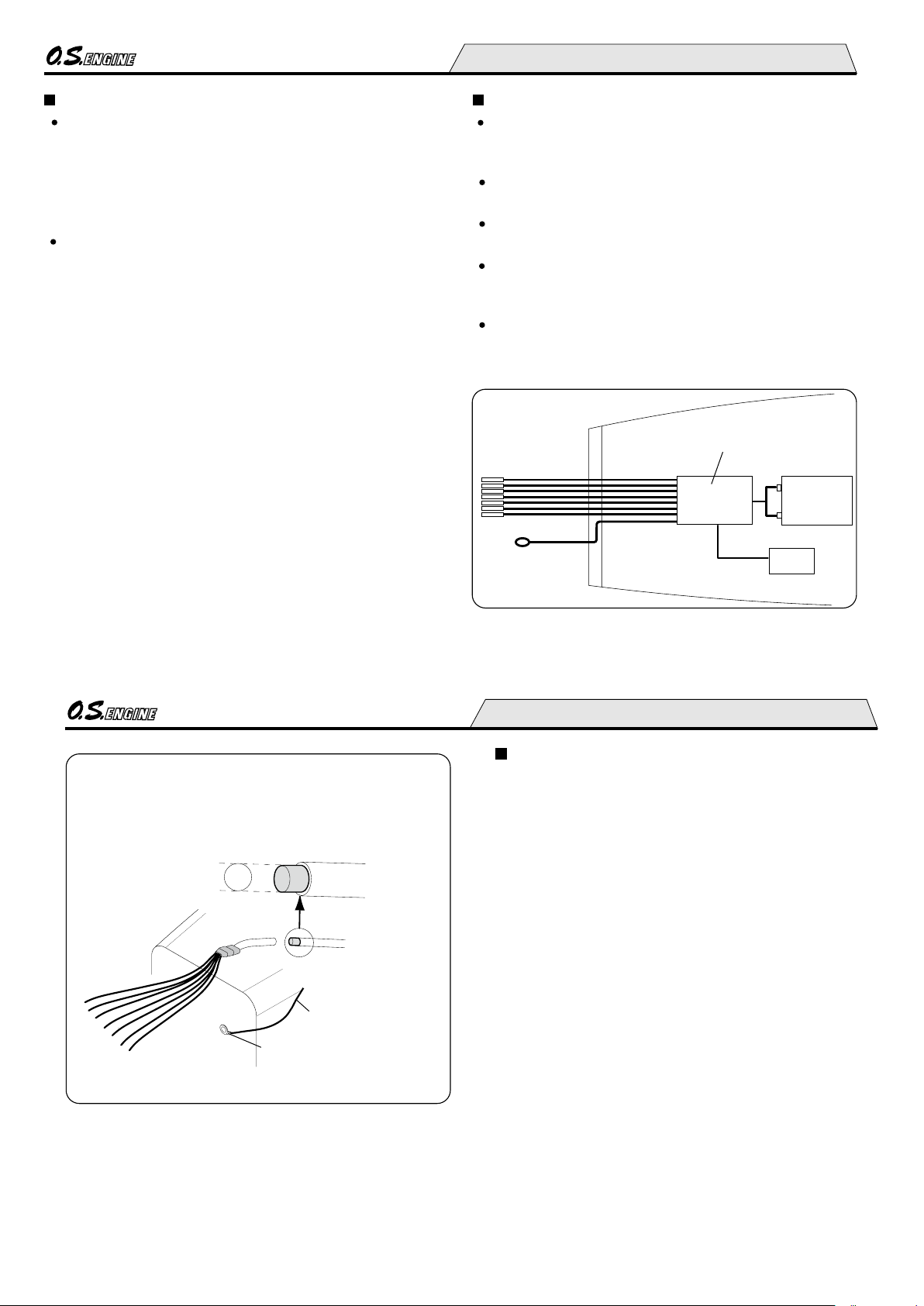
Glowplug leads
Make sure that no part of the wiring touches any part of the
engine, or the wire covering may be melted which causes
short-circuit and fire.
Insert each plug terminal on the plug until you feel two
“clicks”.
Make sure that the plug terminals do not come off before
heating the plugs.
When the plug terminals come off while running or you feel
contact is loose, it is suggested to replace the plug
terminals.
Be sure to install insulating covering (5 O.D., 3 I.D., 12 long
silicone tubing) when replacing the plug terminals.
Receiver
Connect to
each plug
Earth (ground)
lead
On board plug heater
Battery
17
If glowplug leads are extended together as a single cable, use
heavier wire, e.g. cross-section area of 2.0mm multi-strand
copper core as supplied for earth lead.
Earth (ground) lead
Fasten to the
motor mount.
FUEL AND LUBRICATION
Fuel
Suitable fuel for this engine is a methanol based fuel
containing 5~8% nitromethane and 8~10% lubricant.
It is suggested to dilute commercially available 15%
nitromethane and 18% lubricant fuel with methanol halfand-half to make a 7.5% nitromethane and 9% lubricant
fuel.
When you blend a fuel by yourself, use only good quality
methanol, nitromethane and lubricant.
When it is difficult to judge the needle adjustment due to
propeller size and the fuel used, it is suggested to install a
collector ring (optional extra) and apply a muffler
pressurized fuel feed system. Also, installation of the
carburetor insert supplied with the engine (refer to Page 23)
makes it easier to judge the needle adjustment reaction,
while power drops a little.
When a commercially available 15% nitromethane and 18%
lubricant fuel is used, it is suggested to install the carburetor
insert and preferably apply muffler pressurized fuel feed
system.
2.0mm
Note:
Never use a fuel containing more than 15% nitromethane,
or stable performance will not be obtained and the
tendency for rust will be increased.
Page 10

18
Model engine fuel is poisonous. Do not allow it to
come into contact with the eyes or mouth. Always
store it in a clearly marked container and out of the
reach of children.
Model engine fuel is also highly flammable. Keep it
away from open flame, excessive heat, sources of
sparks, or anything else which might ignite it. Do
not smoke, or allow anyone else to smoke, near to it.
Reminder!
Lubrication
The crankcase breather hole is located at the back of the
engine and is fitted with a brass nipple. Fit a length of silicone
tubing of approx. 2.5mm I.D. to this nipple to conduct away
the small amount of oil that escapes through the breather.
Make a habit of draining out the excess oil in the crankcase
at the end of each flying session. Leaving contaminated oil in
the crankcase for a long time will cause rust. Also, residual
castor oil will tend to solidify and lock the engine.
Inject corrosion-inhibiting oil into the crankcase to neutralize
the effects of any remaining contaminants.
2.5mm Silicone tubing
Drain Plug
Breather Nipple
19
STARTING
Precautions
For safety, please observe the following instructions
before starting the engine.
Start the engine by turning the propeller counterclockwise (i.e. normal running direction).
Do not start the engine with the throttle fully opened,
otherwise the model will tend to move forward
suddently due to the strong thrust of the propeller. Hold
both wings of the model when starting the engine.
Do not carry out carburetor adjustments (except needlevalve adjustment) while engine is running.
Use a high-torque electric starter.
Starting procedure is as follows:
Open the needle-valve 2.5
turns from the fully closed
position.
1.
open
Make sure that glowplugs are not connected to the battery.
Do not heat the glowplugs while priming.
2.
Close
3.
open the
throttle fully
Open the throttle fully and apply an electric starter for 5~6
seconds to prime the engine.
Set the throttle valve approximately 1/4 open from the fully
closed position.
4.
Since this is a large engine of 70cc (total displacement),
it generates huge thrust with full throttle.
Be sure to hold the model with two adults and never
allow any part of the body to be in front of the rotating
propeller.
Page 11

20
Starting with an electric starter.
5.
Make sure that the direction of rotation of the starter is
correct.
Connect the glowplug battery.
Apply the electric starter.
When the engine starts, open the throttle valve fully and
keep it running initially (approx. 10 seconds), with original
needle-valve setting.
6.
Make sure that all seven cylinders are firing
7.
The engine is running properly if white smoke is emitted
through all seven exhaust pipes. A slight spray of fuel will be
discharged through the exhaust pipe of any cylinder that is
not firing.
If a cylinder ceases firing, reduce the throttle setting to
approximately 1/4 open from the fully closed position and
re-connect the glowplug battery. The rpm will increase when
all cylinders are firing steadily.
Now disconnect the glowplug battery.
8.
Adjust the needle-valve
9.
Abrupt adjustment of the needle-valve may cause the
engine to stop, especially when it is new and insufficiently
run-in.
As the speed of the engine does not instantly change with
needle-valve readjustment, small movements, with pauses
between, are necessary to arrive at the optimum setting.
Practical best (optimum) needle-valve setting
Approx. 45-90
Maximum rpm setting
("Lean")
"Rich" needle-valbe
setting when starting
the engine.
Rpm starts to decrease.
Close the needle-valve
gradually and slowly.
Engine stops.
With a propeller which the engine turns approx. 6,000rpm
with full throttle, one misfiring cylinder will drop approx.
500rpm and two misfiring cylinders will drop approx.
1,000rpm.
With fully throttle, close the needle-valve gradually to increase
the engine rpm. It is suggested to use a tachometer.
21
Re-starting the engine when warm
To re-start the engine when warm, simply re-energise the
plugs and reapply the starter with the throttle in the idling
position. If the engine does not start, disconnect the battery
from the glowplugs and re-prime. Initially, the high
temperature inside the combustion chambers may turn the
liquid fuel into gas and emit it through the exhaust pipes.
Allow the engine to cool and then repeat the priming
procedure once or twice.
Note:
Make sure that the throttle linkage is made so that the
throttle is fully closed when the throttle lever as well as
trim lever on the transmitter are fully pulled down.
How to stop the engine
Pull down the throttle lever and trim lever on the transmitter
fully.
Page 12

22
Obtain an 22x10 or 23x8 propeller for running-in.
↓
↓
1
2
1. Running-in on the ground
Start the engine
Set the needle-valve 200-300r.p.m. lower than
maximum r.p.m. setting and run approx, 10 seconds.
(It is suggested to use a tachometer.)
Open the needle-valve approx. 200r.p.m. lower than
above setting and run approx. 20 seconds.
Repeat above procedure, i.e., richening and leaning the
mixture until the engine has approx. 10 minutes of running
time.
Keep the throttle fully open, using only the needle-valve to
change r.p.m. Prolonged running-in on the ground is not
suggested because the purpose is just initial running-in
to increace engine temperature gradually close to that of
maximam r.p.m.
NOTE:
2. Running-in in the air
Start the engine
Fly the model.
NOTE: Avoid prolonged heavy load flight.
With each successive flight, close the needle-valve slightly,
until, at the end of 10 flights, the needle-valve is set for
optimum position.
Finish running-in.
The carburetor can now be adjusted for optimum throttle
performance following the instructions given in the next
section.
Set the needle-valve approx 45 open from
optimum position (approx. 45 open from
maximum r.p.m.).
RUNNING-IN ("Breaking-in")
23
THROTTLE VALVE ADJUSTMENT
Needle-valve adjustment
Adjust the needle-valve following the instructions given in
STARTING section.
Mixture control valve adjustment
The carburetor of your enigine has been factory set for the
approximate best result with the fuel tank located in the normal
position (i.e. close to the back of the engine and where the
level of the needle-valve is at 1/3 height of the tank,refer to
Page11), but the setting may, in some cases, vary slightly in
accordance with fuel and climatic conditions.
After running-in is completed and the needle-valve is set at
optimum position (approx 45 open from maximum r.p.m.
position), check the idle speed and adjust only when
necessary.
Rotor Guide Screw
Carburetor Insert
Carburetor Rotor
Installation of the carburetor insert
1. Remove the Rotor Guide Screw.
2. Pull out the Carburetor Rotor.
3. Insert the Carburetor Insert (Be aware of direction.)
4. Reinstall them in the reverse order.
Note that a fuel containing higher nitromethane and
lubricant makes it difficult to judge reactions when opening
and closing the needle, and shortens stable idle running
time.
Never use a fuel containing more than 15% nitromethane, or
correct carburetor adjustments cannot be done and the
tendency for rust will increase.
An approximate 1,500rpm idle speed is possible. However, it
is suggested to set the speed higher than 1,800rpm for more
idle reliability.
Page 13

24
Start the engine.
open the throttle fully .
Adjust the needle-valve.
Close the throttle gradually.
Set the idle speed.
Open the throttle fully.
Does the engine
regain full power?
Continue running at high speed
for 5 seconds.
Close the throttle.
Run at idle speed for 15 seconds.
Does the engine stop?
Apply full throttle.
Does the engine
regain full power
immediately?
OK
Re-set the idle speed
a little higher
Set the thr ot tl e op en in g by
means of the throttle trim on
the transmitter so that the lowest
practical speed, without risk of
the engine stopping,is obtained.
The position where the lowest
pos sible r.p. m. ,w ith steady
running, is obtained.
Approx 40˚ open from maximum
r.p.m. setting.
Yes.
No.
Yes.
One of the cylinders ceases firing.
Disconnect the glowplugs from the battery.
Make sure that all 7 cylinders are firing.
Make sure glowplug switch is on.
The engine hesitates before picking
up to full speed, or appears to run at
medium speed with reduced power.
Check mixture adjustment at idle
speed. Make sure that all cylinders
are firing.
Adjustment should be carried
out after stopping the engine.
Do not move needle-valve
while adjusting other controls.
Repeat the procedure while opening and closing the
throttle until the best result is obtained.
Attention: Do not leave the battery connected while adjusting the carburetor.
One of the cylinders
ceases firing.
One of the cylinders
ceases firing.
25
Adjusting the mixture control valve
1.
Mixture Control Valve
Screwdriver
Turn 30
Alternatively, if the engine stops
or is slow to pick up speed,
without smoking or a strong
exhaust note, it is probable that
the idle mixture is too lean.
2.
Turn 30
In this case, it will be necessary
to turn the Mixture Control Valve
counter-clockwise approximately
1/12 turn (30 ) .
Thirdly, if the rpm increase but the engine appears to run with
reduced power, it is probable that one of the cylinders has
ceased firing. You may detect this by the difference in
exhaust note and rpm compared with previous full-throttle
running. The cutting out of the cylinder may be caused by the
idle speed being set too low or the idle mixture being too rich.
In the case of the idle speed being too low, re-set the idle
position a little higher by means of the throttle trim on the
transmitter. In the case of the idle mixture being too rich, turn
the Mixture Control Valve clockwise about 1/12 turn (30 ).
Normal safe idle speeds are in the region of 1,800 r.p.m..
3.
NOTE:
As this is a seven-cylinder four-stroke-cycle engine,
seven firings take place every two complete revolutions.
Therefore, at first you may have an impression that the
engine is idling at higher r.p.m. than actual running r.p.m.
It is recommended to check the engine r.p.m. with a
tachometer.
Changing the make of glowplug or fuel may sometimes
require re-adjustment of carburetor throttle.
Mixture Control Valve
Carburetor Body
REALIGNMENT OF MIXTURE CONTROL VALVE
In the course of making carburetor adjustments, it is just
possible that the Mixture Control Valve may be inadvertently
screwed in or out too far and thereby moved beyond its
effective adjustment range.
Rotate the Mixture Control Valve until its
slotted head is flush with the carburetor
body. Then, screw it in by 1mm (two turns).
This is the basic position.
If the engine hesitates, puffing
out a good deal of smoke, before
picking up to full speed, it is
probable that the idle mixture is
too rich. In this case, it will be
necessary to turn the Mixture
Control Valve clockwise to lean
the mixture. About 1/12 turn (30 )
should be sufficient.
Page 14

26
FLIGHT & MAINTENANCE
It is necessary to warm up the engine as with a full-size
aircraft or automobile. Do not attempt to take-off immediately
after the engine has been started. Allow the engine to run at
full throttle for at least 10 seconds before releasing the
model.
Checking before flight
Make sure that all seven cylinders are firing.
Make sure that engine runs steadily at idle speed.
Make sure that engine is fully warmed up.
Please pay attention to the matters described below to
ensure that your engine serves you well in regard to
performance, reliability and long life.
As previously mentioned, it is vitally important to avoid
operating the engine in conditions where dust, disturbed by
the propeller, may be deposited on the engine and enter its
working parts.
Remember to keep your fuel container closed to prevent
foreign matter from contaminating the fuel.
Install a fuel filter to prevent dirt and dust in the fuel
container from entering the fuel tank. O.S. Super Filters (L)
is available as an optional extra.
Install an in-line fuel filter between the tank and carburetor
to prevent foreign matter in the tank from entering the
carburetor.
If these precautions are neglected, restriction of fuel flow
may cause the engine to cut out, or the fuel/air mixture to
become too lean causing the engine to overheat.
Clean these filters periodically.
The use of modern high-performance alcohol based model
engine fuels, while promoting cooler running, improved antidetonation combustion and increased power, have the
disadvantage of causing corrosion due to the acid byproducts of combustion. The use of nitromethane in the fuel
can also contribute to the problem.
Care and Maintenance
Sound at full throttle changes when one or two cylinders are
not firing. With a propeller which the engine runs approx.
6,000rpm with full throttle, one misfiring cylinder will drop
approx. 500rpm and two misfiring cylinders will drop approx.
1,000rpm.
27
Do not close the needle-valve and mixture control valve too
far as this will cause a lean setting and over heating of the
engine. This can, in turn, create nitromethane oxide leading
to internal rusting of the engine. Always adjust the
needlevalve slightly on the rich side of peak rpm.
Do not leave unused fuel in the engine at the conclusion of
a day’s flying. Accepted practice is to cut off the fuel supply
while the engine is still running at full throttle, then expel as
much fuel residue as possible by turning the engine over
20-30 seconds with the electric starter. Finally, inject some
after-run oil through the glowplug hole and turn the engine
over several times with the electric starter.
When the engine is not to be used for some months (for
example, as between flying seasons), a worthwhile
precaution is to remove it from the airframe and, after
washing off the exterior with alcohol (not gasoline nor
kerosene), remove carefully the carburetor with intake pipe,
glow plug and all silicone tubing and put them safely aside.
Then, immerse the engine in a container of alcohol. Rotate
the crankshaft while the engine is immersed. If foreign
matter is visible in the alcohol, rinse the engine again in
clean alcohol. Finally, shake off and dry the alcohol ,and
inject some after-run oil in the glowplug hole and rotate the
crankshaft several times by hand. Reinstall the carburetor
with intake pipe and glowplug on the engine and keep it in a
dry place after putting in a vinyl bag.
Page 15

28
VALVE CLEARANCE ADJUSTMENT
ALL O.S. four-stroke engines have their valve (tappet)
clearances correctly set before they leave the factory.
However, if, after many hours of running time have been
logged, a loss of power is detected, or if the engine has to
be disassembled or repaired as a result of an accident,
valve clearances should be checked and readjusted, as
necessary, with the aid of the O.S. Valve Adjusting Tool Kit.
Note:
Valve clearances of all O.S. four-stroke-cycle engines
must be checked and reset ONLY WHEN THE ENGINE IS
COLD. Procedure is as follows:
1.
Remove all the glowplugs except the one installed in the
cylinder that you want to check.
2.
Note:
Each glowplug should be re-installed in to the original
cylinder. You may start to check and adjust with any
cylinder.
Turn the propeller counter-clockwise until compression is
first felt, then turn it futher a quarter turn. At this point, both
valves should be closed.
The standard valve clearance, on both inlet and exhaust
valves, is between 0.04mm and 0.1mm(0.0015-0.004 inch),
measured between valve stem and rocker arm. Use the
0.04mm and 0.1mm feeler gauges to check clearances.
(See Fig.1)
0.04mm
Feeler Gauge
Rocker Arm
Valve
3.
Note:
If the gap is found to be less than 0.04mm, it is not
necessary to readjust the clearance if the engine has
good compression and starts easily. Equally, if the gap
exceeds 0.1mm but is not more than 0.14mm (i.e. the
thickness of both feeler gauges inserted together), it is
not necessary to readjust the clearance if the engine
runs satisfactorily.
Fig.1
If a clearance is found to be outside either of these limits, it
should be reset as follows.
0.04m
m
29
Carefully loosen the locknut
on rocker-arm 1/4-1/2 turn
with 5mm wrench. (Fig.2)
1.
Loosen approx.1/4 to 1/2 turn.
Wrench
Locknut
2.
Turn adjusting-screw approx.
1/2 turn counter-clockwise to
open gap, using appropriate
tool-i.e. Allen hex key. (Fig.3)
Adjusting
Screw
Allen Key
Turn approx.1/2 turn.
3.
Insert 0.04mm feeler gauge
between valve stem and
rocker-arm and gently turn
adjusting screw clockwise
until it stops. (Fig.4)
0.04mm
Feeler Gauge
Turn with fingers
until it stops.
Remove 0.04mm feeler, recheck gap as explained in the
previous page.
5.
If clearance is correct, loosen the locknut on the other
rocker-arm and repeat steps 1 to 5 above.
6.
Remember:
Excessive valve clearance will cause loss of power, due
to valve (s) not opening sufficiently. On the other hand, a
total loss of clearance may cause difficult starting due to
valves not closing properly, resulting in loss of
compression.
Re-tighten locknut while holding adjusting screw stationary.
(Fig.5)
4.
Hold at the
screw head.
Tighten Locknut.
Fig.5
Fig.4
Fig.3
Fig.2
0.04m
m
0.04mm
Note:
The camshaft rotates one turn with every eight propeller
turns and has four projections on the profile. After
adjustment is completed, turn the propeller eight turns to
make sure you feel 4 times normal compression.
Page 16

30
ENGINE EXPLODED VIEW & PARTS LIST
Type of screw
C...Cap Screw N...Round Head Screw
CAP SCREW SETS
(10pcs./sets)
79871020
79871030
79871110
79871060
M2.6x7
M2.6x10
M3x8
M3.5x8
M3.5x15
M3.5x18
M4x15
M4x25
79871090
79871098
79871415
79871425
Code No.
Size
Code No.
Size
1
2
C.M2.6x10
3
4
5
6-5
6-4
6-3
6-2
6-1
6
C.M3.5x18
C.M3.5x15
7
7-1
7-2
8
9
10
C.M3.5x8
11
12
13
14
15-1
15
16
C.M4x25
17
18
19
20-2
20-1
20
21
22
23
24
25
26
27
28
C.M2.6x13
M2.6x13.1
29
30
31
32
33
34
35
36
37
38
39
40
41
42
43
44
45
46
48
47
49
50
51
52-1
52
C.M2.6x7
C.M4x25
46
53
55
54
56
C.M4x10
C.M3x8
57
C.M2.6x7
58
N.+M3x22
59
60
C.M4x15
C.M4x15
31
The specifications are subject to alteration for improvement without notice.
1
2
3
4
5
6
6-1
6-2
6-3
6-4
6-5
7
7-1
7-2
8
9
10
11
12
13
14
15
15-1
16
17
18
19
20
20-1
20-2
21
22
23
24
25
26
27
28
29
30
31
32
47104200
47161100
45061202
47161120
47161500
47104000
47104100
44851000
45960210
45960310
45960400
45269000
45269100
45069200
47114010
47003100
47103300
44603400
45603200
45606000
29310100
47108000
29208200
29031009
47101600
47164000
47066000
47166100
24881824
47166210
47031000
47162700
47131000
47101610
47101100
47101000
47102100
47062300
47162600
47162500
47162000
47162100
33
34
35
36
37
38
39
40
41
42
43
44
45
46
47
48
49
50
51
52
52-1
53
54
55
56
57
58
59
60
47030000
47162400
47062200
47130000
47102000
47002300
47105400
47105000
47005300
47105410
47002200
47102310
47102400
47131100
47109500
47109400
47101810
24025923
47101800
47168000
45515000
47107100
44516110
29714200
47101700
47181140
47181000
71912110
71912100
71615009
46471000
72200060
72200200
72200170
72200171
72200190
72200180
47181210
72200080
71912150
79870050
79871525
Description
Code No.
No.
DescriptionCode No.
No.
Rocker Cover
Rocker Arm
Tappet Adjusting Screw
Rocker Arm Thrust Washer (2pcs.)
Rocker Arm Shaft
Cylinder Head (W/Valve Assembly)
Cylinder Head
Valve (1pc.)
Valve Spring (1pc.)
Valve Spring Retainer (1pc.)
Cotter Pin (2pcs.)
Exhaust Pipe Assembly
Exhaust Pipe
Exhaust Pipe Lock Nut
Head Gasket
Cylinder Liner
Cylinder Jacket
Piston Ring
Piston
Piston Pin
Propeller Locnut Set
Drive Hub
Woodruff Key
Ball Bearing (Front)
Front Housing
Cam Follower (2pcs.)
Push Rod Set (S&L 1Piece Each)
Push Rod Cover Set (S&L 1Piece Each)
"O" Ring (2pcs.)
"O" Ring (2pcs.)
Reduction Gear Bearing (Front)
Reduction Gear
Reduction Gear Bearing (Rear)
Front Plate
Crankcase Locating Pin
Crankcase
Crankshaft Spacer
Cam Thrust Washer (B)
Cam Assembly Screw
Cam Gear
Intake Cam
Exhaust Cam
Cam Holder Bearing
Cam Holder
Cam Thrust Washer (A)
Ball Bearing (Rear)
Crankshaft
Master Connecting rod Spacer
Link Pin
Master Connecting Rod Assembly
Link Rod
Link Pin E Ring
Crank Pin Washer
Crank Pin Stop Screw
Drive Shaft
Drive Shaft Bearing
Wave Washer (8mm)
Drive Shaft Spacer
Back Plate Parallel Pin
Nipple No.2 (5mm)
Back Plate
Intake Manifold Set
"O" Ring (2pcs.)
Impeller
Drive Shaft Retaining Screw
"O" Ring (1.2x54)
Rear Cover
Carburetor Spacer
Carburetor Complete (80T)
Radial Mount Stand Off
Radial Mount
Glow Plug Type F
Drain Plug
Valve Adjusting Kit
Boostre Cable Set For Single Cylinder
Plug Cable Set
Plug Cable
Plug Terminal
Earth Cable 5
Carburetor Insert
Needle-Valve Extension Cable Set
Radial Mount Retaining Screw Set
Blind Nut M5 (10pcs.)
Cap Screw M5x25 (10pcs.)
Page 17

32
Type of screw
N...Round Head Screw S...Set Screw
The specifications are subject to alteration for improvement without notice.
Description
Code No.
No.
EXPLODED VIEW & PARTS LIST
Needle Assembly
Needle Holder Assembly
Ratchet Spring
Carburetor Body
Fuel Inlet (Nipple No.1)
Carburetor Rubber Gasket
Roter Guide Screw
Mixture Control Valve Assembly
"O" Ring (2pcs.)
"O" Ring (2pcs.)
Carburetor Rotor
Throttle Lever
Throttle Lever Retaining Screw
Carburetor Retaining Screw (2pcs.)
1
2
2-1
3
4
5
6
7
7-1
7-2
8
9
9-1
10
47181970
27381940
26711305
47181100
22681953
46115000
45581820
47181600
46066319
24881824
47181200
22081408
22081313
45581700
N.+M3x6
S.M3x3
1
2
3
4
5
6
7
8
9
9-1
N.+M3x22
2-1
7-1
7-2
10
33
(46210300)
(71531000)
(72403050)
(79870050)
(55500004)
(71521000)
(71531010)
COLLECTOR EXHAUST PIPE
NON-BUBBLE WEIGHT
SUPER FILTER (L
)
LONG SOCKET WRENCH
WITH PLUG GRIP
O.S. GENUINE PARTS & ACCESSORIES
PROPELLER
LOCKNUT SET FOR 4C SPINNER
The specifications are subject to alteration for improvement without notice.
M5
BLIND NUT (10pcs.)
LOCK WASHER (10sets)
M5
NON-BUBBLE WEIGHT
S
3/8"-M5 (L)
(47169000)
Page 18

34
Dimensions (mm)
THREE VIEW DRAWING
Specifications
Displacement
Bore
Stroke
PracticalR.P.M.
Output
Weight
158.5
122
36
36
72
230
72
UNF3/8-24
9.95 cc x 7 / 0.607 cu.in. x 7
24.0 mm / 0.945 in.
22.0 mm / 0.866 in.
1,500-7,000r.p.m.
3,167 g / 111.71 oz.
C
Copyright 2010 by O.S.Engines Mfg. Co., Ltd. All rights reserved. Printed in Japan.
600 92360 0 810 02
TEL. (06) 6702-0225
FAX. (06) 6704-2722
6-15 3-Chome Imagawa Higashisumiyoshi-ku
Osaka 546-0003, Japan
URL : http://www.os-engines.co.jp
 Loading...