

Page 1
It is of vital importance, before attempting to
operate your engine, to read the general
'SAFETY INSTRUCTIONS AND WARNINGS'
section on pages 2-6 of this booklet and to strictly
adhere to the advice contained therein.
●
Also, please study the entire contents of this
instruction manual, so as to familiarize yourself
with the controls and other features of the
engine.
●
Keep these instructions in a safe place so that
you may readily refer to them whenever
necessary.
●
It is suggested that any instructions supplied
with the aircraft, radio control equipment, etc.,
are accessible for checking at the same time.
Page 2

CONTENTS
SAFETY INSTRUCTIONS AND WARNINGS
ABOUT YOUR O.S. ENGINE
INTRODUCTION
INSTALLATION OF THE ENGINE
I
NSTALLATION OF SILENCER
NEEDLE-VALVE LOCATION
BEFORE STARTING
ADVICE ON SELECTION OF FUEL,
GLOW PLUG & PROPELLER
STAR TING THE ENGINE
RUNNING-IN (Breaking-in)
2~6
10
~
12
10
12~14
14
~
22
23
CARBURETTOR
CARBURETTOR AIR-BLEED
ADJUSTMENT
7
TROUBLE SHOOTING WHEN THE
8
ENGINE FAILS TO START
9
CARE AND MAINTENANCE
OPTIONAL PARTS & ACCESSORIES
ENGINE EXPLODED VIEW &
PARTS LIST
CARBURETTOR EXPLODED
VIEW & PARTS LIST
THREE VIEW DRAWING
1
23
26
30
37
~
24
25
~
27
28
29
~
35
36
~
38
Page 3
SAFETY INSTRUCTIONS AND WARNINGS ABOUT YOUR O.S. ENGINE
Remember that your engine is not a "toy", but a highly efficient internalcombustion machine whose power is capable of harming you, or others, if it is
misused.
As owner, you, alone, are responsible for the safe operation of your engine, so act
with discretion and care at all times.
If at some future date, your O.S. engine is acquired by another person, we would
respectfully request that these instructions are also passed on to its new owner.
The advice which follows is grouped under two headings according to the
degree of damage or danger which might arise through misuse or neglect.
WARNINGS
These cover events which
might involve serious (in
extreme circumstances, even
fatal) injury.
NOTES
These cover the many other
possibilities, generally less obvious
sources of danger, but which, under
certain circumstances, may also
cause damage or injury.
2
Page 4
WARNINGS
Never touch, or allow any object to come
•
into contact with, the rotating
propeller and do not crouch
over the engine when it is
running.
A weakened or loose propeller may
•
disintegrate or be thrown off and, since
propeller tip speeds with powerful
engines may exceed 600 feet(180 metres)
per second, it will be understood that
such a failure could result in serious
injury, (see 'NOTES' section relating to
propeller safety).
Model engine fuel is poisonous. Do not
•
allow it to come into contact with the eyes
or mouth. Always store it in a
clearly marked container and
out of the reach of children.
Model engine fuel is also highly
•
flammable. Keep it away from open flame,
excessive heat, sources of sparks, or
anything else which might
ignite it. Do not smoke or allow
anyone else to smoke, near to it.
•
Never operate your engine in an enclosed space. Model engines, like automobile engines, exhaust deadly carbonmonoxide. Run your engine only in an
open area.
Model engines generate considerable
•
heat. Do not touch any part of your
engine until it has cooled. Contact with
the muffler (silencer),
cylinder head or exhaust
header pipe, in particular,
may result in a serious burn.
3
Page 5
NOTES
This engine was designed for model
•
aircraft. Do not attempt to use it for any
other purpose.
Mount the engine in your model securely,
•
following the manufacturers' recommendations, using appropriate screws and locknuts.
Be sure to use the silencer (muffler)
•
supplied with the engine. Frequent
exposure to an open exhaust may
eventually impair your hearing.
Such noise is also likely to cause
annoyance to others over a wide area.
If you remove the glowplug from the engine
•
and check its condition by connecting the
battery leads to it, do not hold the plug with
bare fingers.Use an appropriate tool or a
folded piece of cloth.
Fit a top-quality propeller of the diameter
•
and pitch specified for the engine and
aircraft. Locate the propeller on the shaft so
that the curved face of the blades faces
forward-i.e. in the direction of flight. Firmly
tighten the propeller nut, using the correct
size wrench.
4
Page 6

NOTES
Always check the tightness of the propeller
•
nut and retighten it, if necessary, before
restarting the engine, particularly in the
case of four-stroke-cycle engines. If a
safety locknut assembly is provided with
your engine, always use it. This will prevent
the propeller from flying off in the event of a
"backfire", even if it loosens.
If you fit a spinner, make sure that it is a
•
precision made product and that the slots
for the propeller blades do not cut into the
blade roots and weaken them.
Preferably, use an electric starter. The
•
wearing of safety glasses is also strongly
recommended.
Discard any propeller which has become
•
split, cracked, nicked or otherwise rendered
unsafe. Never attempt to repair such a
propeller: destroy it. Do not modify a propeller
in any way, unless you are highly experienced
in tuning propellers for specialized
competition work such as pylon-racing.
Take care that the glow plug clip or battery
•
leads do not come into contact with the
propeller. Also check the linkage to the
throttle arm. A disconnected linkage could
also foul the propeller.
After starting the engine, carry out any
•
needle-valve readjustments from a safe
position behind the rotating propeller. Stop
the engine before attempting to make other
adjustments to the carburettor.
5
Page 7
NOTES
Adjust the throttle linkage so that the engine
•
stops when the throttle stick and trim lever
on the transmitter are fully retarded.
Alternatively, the engine may be stopped by
cutting off the fuel supply. Never try to stop
the engine physically.
Take care that loose clothing (ties, shirt
•
sleeves, scarves, etc.)do not come into
contact with the propeller.Do not carry loose
objects (such as pencils, screwdrivers, etc.)
in a shirt pocket from where they could fall
through the propeller arc.
Do not start your engine in an area
•
containing loose gravel or sand.
The propeller may throw such material in
your face and eyes and cause injury.
For their safety, keep all onlookers
•
(especially small children) well back (at
least 20 feet or 6 meters) when preparing
your model for flight. If you have to carry
the model to the take-off point with the
engine running, be especially cautious.
Keep the propeller pointed away from you
and walk well clear of spectators.
Warning! Immediately after a glowplug-
•
ignition engine has been run and is still
warm, conditions sometimes exist whereby
it is just possible for the engine to abruptly
restart if the propeller is casually flipped
over compression WITHOUT the glowplug
battery being reconnected. Remember this
if you wish to avoid the risk of a painfully
rapped knuckle!
6
Page 8
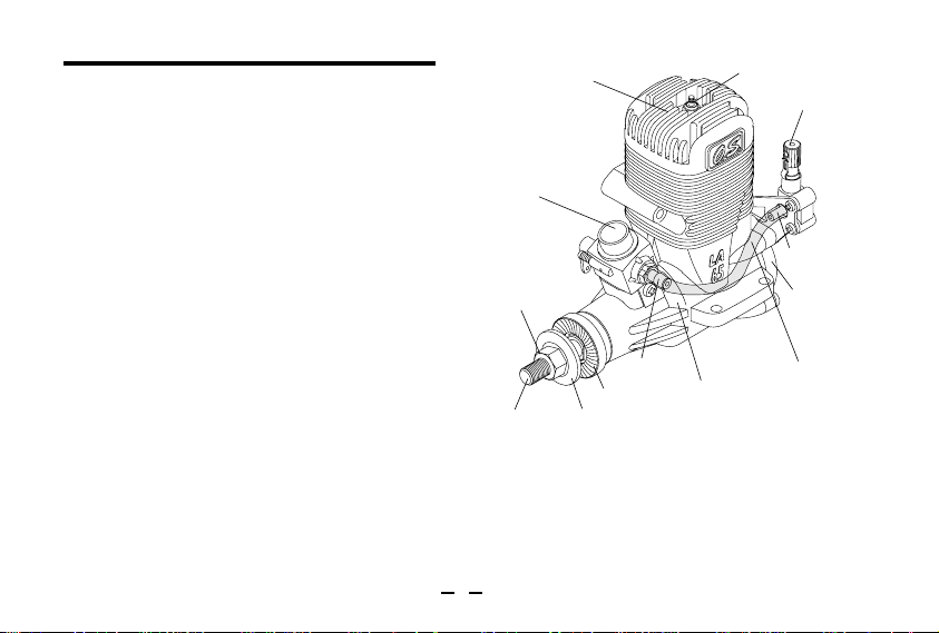
INTRODUCTION
THE MAX-40LA, 46LA and 65LA have been developed
to meet the requirements of beginners and sport flyers.
Of modern design and having a separate needle-valve
unit mounted at the rear, where manual adjustment is
safely remote from the rotating propeller, they offer the
advantages of reliability and easy handling, at lower
cost. Like all O.S. engines they are built to standards
of engineering excellence that have evolved through
more than 60 years' experience in the design and
production of model internal-combustion engines.
Advanced modern precision machinery, top quality
materials and the efforts of highly skilled craftsmen and
technicians are combined to ensure a continuation of
the levels of performance, durability and reliability for
which O.S. is world famous.
The MAX-46LA has a larger cylinder diameter , but both
the 40LA and 46LA engines have the same external
dimensions.
The 'midnight blue' external finish may be
decolorized by very high surface temperature or
by certain solvents. Such decolorization does not
affect engine perfor-mance, however.
Cylinder head
Carburettor
Propeller nut
Crankshaft
Fuel inlet
Drive Hub
Propeller washer
Glowplug
Needle valve
Fuel outlet
Cover Plate
Silicone Tube
Crankcase
Connect the short length of fuel tubing supplied
securely between the fuel outlet and the fuel inlet. In
the event of the tube becoming damaged, it should be
replaced with a suitable length of best quality 5mm
ODX2mm ID silicone tubing. Use similar material to
connect the fuel inlet nipple to the fuel tank.
7
Page 9
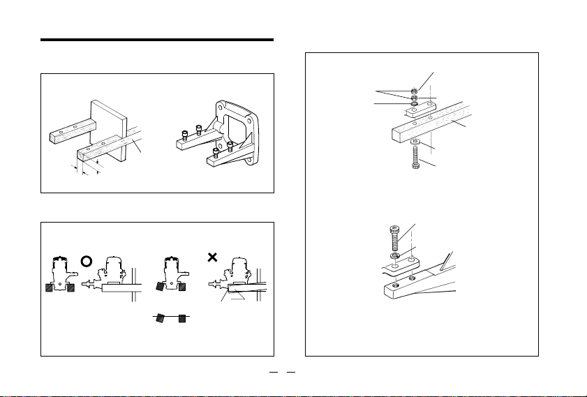
INSTALLATION
Installation in the model
A typical method of beam
mounting is shown below,left.
At least
12mm(1/2")
At least
12mm(1/2")40-46LA
15mm(5/8")65LA
Make sure that the mounting beams are parallel
and that their top surfaces are in the same plane.
CORRECT
O.S. radial motor mount
(Available as an optional extra part.
See parts list)
Rigid hardwood
(e.g. maple)
INCORRECT
How to fasten the mounting screws.
3mm steel nuts
(40-46LA)
4mm(65LA)
Spring washer or
lock washer
Tighten second nut firmly
down onto first nut.
Tighten this nut first.
Steel washer
3.5mm steel screw
(40-46LA)
4mm(65LA)
Hardwood mounting beams
3mm steel Allen screw
Spring washer
Hardwood such as
cherry or maple.
Front view
Side view
Top surfaces are in the
same plane.
Top surfaces are not
in the same plane.
Re-align the surfaces
as necessary
Opposite beam
Top surfaces
are not in the
same plane.
Engine does
not seat firmly.
O.S. radial motor mount
(cast aluminum)
8
Page 10
NEEDLE-VALVE EXTENSION
The needle-valve supplied with these engines is
designed to incorporate an extension so that, when
the engine is enclosed within the fuselage, the
needle-valve may be adjusted from the outside.
Cut a commercially available rod to the required
length, bend one end to an L shape, insert it into
needle's center hole and secure it by tightening the
set-screw in the needle-valve knob with 1.5mm. Allen
key.
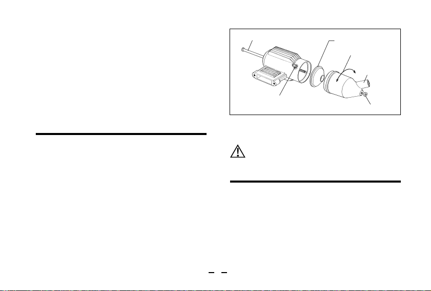
INSTALLATION OF SILENCER
The angled exhaust of the silencer can be rotated to
any desired position in the following manner:
1) Loosen the locknut and assembly screw.
2) Set the exhaust outlet at the required position by
rotating the rear part of the silencer.
3) Re-tighten the assembly screw, followed by the
locknut. The standard silencer is quite effective but
reduces power to some degree.
Assembly screw
Exhaust pressure nipple
Reminder!
Model engines generate considerable heat. Do
not touch any part of your engine until it has
cooled. Contact with the muffler (silencer),
cylinder head or exhaust header pipe, in
particular, may result in a serious burn.
Cone baffle
Turn to requlred position
Exhaust outlet
NEEDLE-VALVE LOCATION
As delivered from the factory, the MAX-40LA, 46LA &
65LA have the needle-valve assembly installed
vertically. However, if more convenient for a particular
installation, the needle-valve may be reinstalled
horizontally.
The procedure for relocating the needle-valve is as
follows:
9
Locknut
Page 11
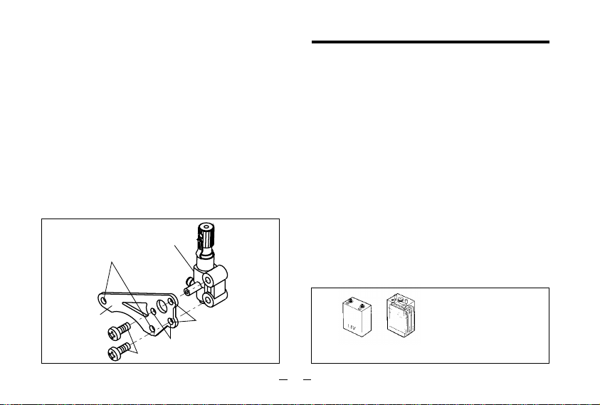
Remove the two cover-plate screws which secure
1.
the needle-valve assembly bracket, then carefully
remove the two screws by which the needle-valve
unit is attached to the bracket.
2.
Rotate the needle-valve unit through 90˚ and reattach it to the bracket in the required position (see
sketch right).
Note:
As self-tapping screws are used for unit
attachment, screw them in carefully so that screw
threads match those of the unit body precisely.
3.
Finally, secure the complete assembly to rear cover
plate as before.
Needle Valve unit
Cover plate fitting holes
Needle-Valve
Assembly Bracket
Needle Valve unit attachment screws
Vertical position
(Factory position)
Horizontal position
BEFORE STARTING
Tools, accessories, etc.
The following items are necessary for operating the
engine.
1 Fuel
Model glowplug engine fuel of good quality, preferably
containing a small percentage of nitromethane. (See
"Advice on selection of fuel, glowplug and propeller")
2 Glowplug
O.S. A3 glowplug is installed in the engine.
3 Propeller
Suggested size is 11X5 (40LA), 11X6 (46LA), or 12X6
(65LA).
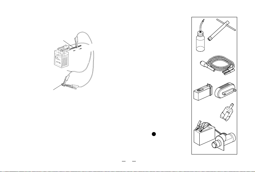
4 Glowplug battery
The power source for heating the glowplug may be
either a large heavy-duty 1.5volt dry cell, or preferably,
a 2-volt rechargeable lead-acid cell (accumulator).
If a 2-volt cell is employed,
use a resistance wire, as
shown, to reduce applied
voltage, otherwise the element
1.5 volt heavy-duty
dry battery
10
will overheat and burn out.
or 2 volt rechargeable
lead-acid cell (at least 5Ah)
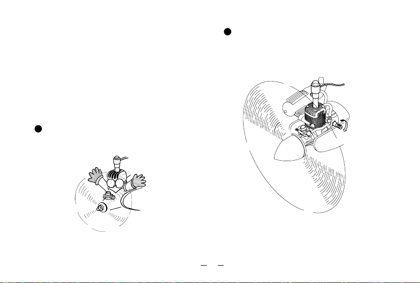
Page 12
Warning (Very hot)
Never touch the nichrome wire while the battery is
connected.
Resistance coil
(nichrome wire)
Battery leads
Adjust applied voltage by changing the position of clip on
resistance coil until glowplug element is glowing bright red.
Raise
voltage to
increase
brightness.
Lower voltage to
reduce brightness.
5 Plug wrench
Used for tightening glowplug. The O.S. long plug
wrench is available as an optional accessory.
6 Battery leads
These are used to conduct current from the battery to
the glowplug. Basically, two leads, with clips, are
required, but, for greater convenience, twin leads with
special glowplug connectors, as shown on the right,
are commercially available.
7 Fuel tank
For installation in the model,
a 200cc(7oz.) for 40.46LA, or
a 350cc(12oz.) for 65LA, is
suggested.
8 Fuel bottle or pump
For filling the fuel tank, a
simple, polyethylene
"squeeze" bottle, with a
suitable spout,is all that is
required. Alternatively, one of
the purpose-made manual or
electric fuel pumps may be
used to transfer fuel directly
from your fuel container to the
fuel tank.
9 Fuel can filter
Fit a filter to the outlet tube of
your refuelling container to
prevent entry of foreign
matter into the fuel tank.
(Refer to of STARTING
4
THE ENGINE section.)
11
Fuel bulb
Battery leads
Fuel pumps
Electric
Fuel Can Filter
12V Battery
For tightening
glowplug
Manual
Starter
Page 13

10 Silicone tubing
This is required for the connection between the fuel tank
and engine.
11 Electric starter and starter battery
An electric starter is recommended for starting.
Fuel and pressure lines
Connect suitable lengths of silicone tubing, as
illustrated, after installing the engine.
Fuel lines and position of fuel tank
Locate the fuel tank so that the top of the tank is 510mm (1/4-3/8") above the level of the needle-valve.
Note: When cutting silicone tubing......
Use knife or razor blade.
*If you should need to clean out silicone tubes, use methanol
or glow-fuel, not gasoline.
Pay attention to tank height
Silicone tubing
Fuel level
6~8
mm
Do not use wire
cutters or pliers
Silencer (muffler) pressurized fuel system
To reduce variation in fuel "head" and ensure steady
fuel delivery at the carburettor, it is advisable to employ
a silencer (muffler) pressurized fuel system, i.e. to use
the silencer outlet nipple to pressurize the fuel tank as
shown at left.
ADVICE ON SELECTION OF FUEL, GLOWPLUG & PROPELLER
Fuel
Use a good quality commercial fuel or one of the blends
shown in the table. Fuel "A" is suitable for running-in and
ordinary use. Fuel "B" is for use when more power is required
and for improved flexibility. Note that even a small quantity
of nitromethane (3-5%) will improve flexibility, making the
needle-valve adjustment less critical and improving throttle
response. Use only materials of the highest purity. Synthetic
oils are permissible but are less tolerant of a "lean run" than
castor-oil. If, therefore, a synthetic lubricant is used in the
fuel, readjust the needle-valve to a slightly richer setting, as
a safety measure, in case the fuel/air mixture becomes too
lean through maneuvers in flight. If a more powerful fuel is
used, the engine should be checked out to make sure that
it is sufficiently run-in to operate on that particular fuel
without overheating. Do not use fuels containing less than
18% lubricant.
12
Page 14

A
Methanol
Castor Oil
Nitromethane
Reminder!
Model engine fuel is poisonous. Do not
allow it to come into contact with the eyes or
mouth. Always store it in a clearly marked
container and out of the reach of children.
Model engine fuel is also highly flammable.
Keep it away from open flame, excessive
heat, sources of sparks, or anything else
which might ignite it. Do not smoke, or allow
anyone else to smoke, near to it.
PROPELLER
Suggested propeller sizes are given in the table.
As the ideal propeller diameter, pitch and blade area
vary according to the size, weight and type of model,
final propeller selection will require in flight
experimentation.
75%
20%
5%
B
65%
20%
15%
Reminder!
Never touch, or allow any object to come
into contact with, the rotating propeller and
do not crouch over the engine when it is
running.
LA Series
40LA
46LA
65LA
GLOWPLUG
An O.S. A3 glowplug is installed in the engine.
Other recommended O.S. plugs are Nos.8 and A5.
Carefully fit plug finger-tight, before final tightening
with the correct size plug wrench.
Running-in
11✕5
✕6
11
✕6
12
Trainer & Sport
10✕6~7,10.5✕6,11✕5~6
11✕6~7
✕7
~
8,13✕6~8
12
The role of the glowplug
With a glowplug engine, ignition is initiated by the
application of a 1.5-volt power source. When the battery
is disconnected, the heat retained within the combustion
chamber remains sufficient to keep the plug filament
glowing, thereby continuing to keep the engine running.
Ignition timing is 'automatic' : under reduced load,
allowing higher rpm, the plug becomes hotter and,
appropriately, fires the fuel/air charge earlier;
conversely, at reduced rpm, the plug become cooler and
ignition is retarded.
13
Page 15

Glowplug life
Particularly in the case of very high performance engines,
glowplugs must be regarded as expendable items.
However, plug life can be extended and engine
performance maintained by careful use, i.e.:
Install a plug suitable for the engine.
•
Use fuel containing a moderate percentage of
•
nitromethane unless more is essential for racing
events.
Do not run the engine too lean and do not leave the
•
battery connected while adjusting the needle.
When to replace the glowplug
Apart from when actually burned out, a plug may
need to be replaced because it no longer delivers its
best performance, such as when:
Filament surface has roughened and turned white.
•
Filament coil has become distorted.
•
Foreign matter has adhered to filament or plug
•
body has corroded.
Engine tends to cut out when idling.
•
Starting qualities deteriorate.
•
STARTING THE ENGINE
Preparations
1 Installing the glowplug
Install the washer on the
glowplug and screw carefully into
cylinder-head, making sure that
it is not cross-threaded before
tightening firmly.
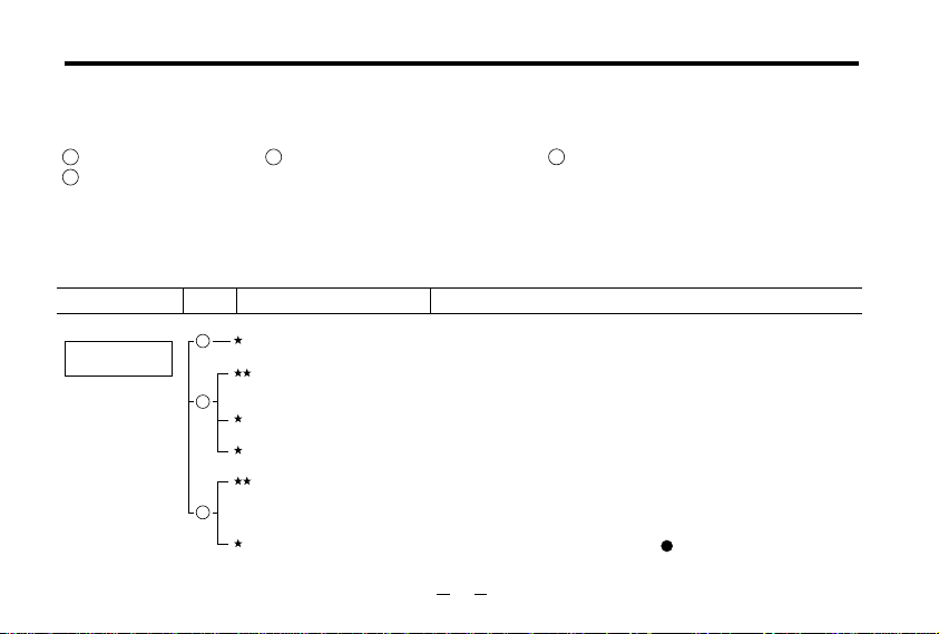
2 Installing the propeller
First, mount the propeller on the engine by tightening
the prop nut or spinner-nut lightly, and make sure of
the position where compression is felt, turning the
propeller counter-clockwise slowly. Then tighten
firmly as explained below.
For accurately centering the
starter's rubber drive insert,
use an O.S. solid alloy
spinner-nut. (Available as an
optional extra part).
Alternatively, a spinner
assembly, enclosing the
propeller boss, may be
used, but make sure
that it is of sturdy
construction and that the spinner shell does not
loosen when the starter is used.
Wrench
Glow plug
Washer
14
Page 16

Warning: When using a spinner assembly, make
sure that the notches in the spinner shell are
large enough to clear the propeller blades and so
do not cut into and weaken the blade roots.
Tighten the spinner nut firmly so that compression is
first felt as indicated (i.e. with blades horizontal) when
turning the propeller in the direction of arrow.
4 Filling the fuel tank
Do not allow fuel to overflow into
silencer when refuelling, otherwise
engine may become flooded and
difficult to start.
3 Checking for compression leakage
Check compression
leakage by turning
the propeller up to
this position after
compression is felt.
If leakage is detected, remove the
glowplug, carefully wipe threads,
re-insert and tighten firmly.
Dribble a few drops
of fuel around the
glowplug and look
for air bubbles.
Compression is first
felt around this posit
ion when turning
the propeller slowly.
15
Re-connect
delivery tube
to engine after
tank is filled.
Fuel pump
Use a fuel can filter
(e.g. O.S. Super Filter).
Disconnect delivery tube
from the fuel inlet, and
connect it to the tubing
from the fuel pump.
Do not let dirt or
dust enter fuel can.
Fuel (model
glow-plug
engine fuel)
Page 17

5 Opening and closing of the needle-valve
Close
Open
Turn needle-valve clockwise to close (for leaner mixture).
Turn needle-valve counter-clockwise to open (for richer mixture).
6 Setting the needle-valve
Open the needle-valve 1 turns (for 40,46LA) and 2 turns
(for 65LA) in the direction of arrow from the closed position.
1
2
1
2
7 Open the throttle fully
Fully closed position
Fully opened position Throttle
8 Priming
Close
Open
Fuel Tube
Needle-valve
The position where the needle-valve stops is the fully closed
position. It may be convenient to remember the position of the
mark or set-screw at this time.
Place your finger
over the carburettor
to choke intake.
Turn the propeller
two revolutions
while watching
the fuel line.
16
Fuel inlet
Fuel will flow
from tank to
carburettor as
propeller is
turned.
Page 18

Priming quantity
After fuel has been drawn to the carburettor, flip the
propeller two more revolutions, with intake choked, to
draw fuel into engine.
Above procedure is called priming.
NOTE (IMPORTANT)
The quantity of fuel drawn into the engine by
priming is an important factor in starting the
engine successfully.
When the engine is being started for the first time,
turn the propeller two revolutions after fuel reaches
the fuel inlet, as described above. However, when restarting the engine immediately after a run, one
revolution, or even no priming at all may be required.
The engine's requirements will be quickly learned
with experience.
9
Do not energize the glowplug at this stage.
Turn the propeller 3 to 4
turns counter-clockwise
smartly by finger in the
direction of arrow. Turn
approx. 10 turns instead
when the engine is cold.
17
Page 19

10
Hold model securely when starting
Glowplug battery.
Place as far to the
rear as possible.
Starter
Be careful not
to be hit by propeller!
11
Setting the throttle
Assistant should hold
the model so that it
cannot move forward
when the engine starts.
Assistant
12
Heat glowplug
Connect battery leads as shown
(polarity is immaterial.)
13
Apply electric starter
Starting battery
Fully closed
position
1
3
Set at this Position.
2
3
Fully opened
position
18
Page 20
Check that the throttle is one-third open from the fully
closed position. Bring the starter into contact with the
spinner nut or spinner and depress the starter switch
for one or two seconds. Repeat if necessary. When
the engine fires, withdraw the starter immediately.
Attention: Never place your finger over the
carburettor intake when applying the starter. Such an
action will cause an excess quantity of fuel to be
drawn into the cylinder and result in hydraulic lock
that may damage the engine.
14
Engine starts
If the engine does not start, refer to the TROUBLE
SHOOTING CHART on page 26-27.
BEWARE of
the rotating
propeller.
15
Needle-valve adjustment(1)
Slowly advance throttle to its fully open position, then gradually
close the needle-valve until the exhaust sound changes from
an irregular pitch (four-cycle) to a steady pitch (two-cycle).
Listen to the sound
carefully.
In the interests of safety, keep your face and other parts of the
body away from the vicinity of the propeller.
Close the needlevalve gradually until the engine sound is
changing from a four-cycle into a two-cycle in pitch.
19
Page 21

16
Disconnect battery leads
Disconnect the battery
leads from the engine
with care so that the
plug clip does not touch
the rotating pro-peller.
If the engine stops when battery leads are disconnected,
close the needle-valve a little (approx. 30˚) further, and restart
the engine.
17
Needle-valve adjustment(2)
As the needle-valve is closed beyond the initial readjustment,
the r.p.m. of the engine will be increased and a continuous
high-pitched exhaust note, only, will be heard.
Key to the needle-valve
adjustment.
(Turn 10-15˚ at a time.)
Turn the needle-valve 10-15˚ in the direction of arrow, and
wait momentarily for the change of r.p.m.
After the r.p.m. of the engine increases, turn the needle-valve
another 10-15˚ and wait for the next change of r.p.m.
As the speed of the engine does not instantly change with
needle-valve readjustment, small movements, with pauses
between, are necessary to arrive at the optimum setting.
IMPORTANT NOTE
When fine-tuning the needle-valve to reach peak performance, take care not to run the engine too lean
and cause it to overheat.
Be sure to observe the simple running-in procedures
described on Page 22.
20
Page 22

18
Needle-valve adjustment(Summary)
67
Practical best(optimum) needle-valve setting
Clear, high-pitched two-stroke
exhaust note
Maximum rpm setting("Lean").
20~30˚
5
Intermittent, high-pitched
two-stroke note superimposed
on low "four-stroke" sound.
4
Disconnect battery leads from
glowplug at about this point.
3
Exhaust note starts to change.
Note: Although this is a two-stroke engine it fires like
a four-stroke at these rich needle-valve settings-i.e.
ignition of the fuel charge takes place at every fourth
stroke of the piston instead of at every second
stroke.
NOTE: The above sketch is for reference purposes only.
Actual needle positions may differ from those shown.
2
The engine may stop if the battery leads
are disconnected from the glowplug while
the engine is running rich.
e
R
o
t
E
e
n
n
i
g
s
s
t
p
o
1
"Rich" needle-valve
setting when starting
the engine.
t
t
e
r
d
a
t
s
o
t
s
.
n
e
s
o
i
t
a
u
e
l
r
o
c
v
e
d
On starting from cold, with the needle-valve
set at the rich starting position:
a good deal of white smoke is emitted, accompanied by
a relatively low-pitched "four-stroke" exhaust note.
As the needle-valve is closed and the r.p.m. increases:
an intermittent high-pitched two-stroke note will be superimposed
on the low-pitched "four-stroke" note.
Exhaust smoke will be less dense and grey in colour.
Further needle-valve closure:
exhaust note is now a steady high-pitched sound,rising
higher in pitch as needle-valve is closed and
The grey smoke will be lighter.
(However, make sure that engine is fully run in.)
Finally:
maximum rpm is reached and will fall off (or engine will
stop) if needle -valve is closed any further.
Exhaust gas will be very light.
Now, re-open needle-valve 20-30˚
This will produce the practical best (i.e. optimum)
rpm setting (lower than maximum rpm).
A light grey exhaust emission may be observed.
Take note of this position of the needle-valve.
21
increase.
Page 23

Subsequent starting procedure
Once the optimum needle-valve setting has been
established (see "Needle-valve adjustmentSummary") the procedure for starting is simplified as
follows:
1) Open the needle-valve one half-turn (180˚) from
the optimum setting.
2) Open the throttle fully, place your finger over the
carburettor intake and rotate the propeller through
two revolutions to prime the engine.
3) Set the throttle one-third open from the fully closed
position, energize the glowplug and apply the
starter. When the engine starts, re-open the
throttle and re-adjust the needle-valve to the
optimum setting.
Note: When re-starting the engine on the same
day, provided that atmospheric conditions have
not changed significantly, it may be practicable to
re-start the engine on its optimum (running)
setting. Also, if the engine is being re-started
immediately after a run (i.e.hot), priming should
not be necessary.
18
19
How to stop the engine
Close the throttle to reduce to the lowest possible r.p.m.
Close
With the transmitter throttle trim lever fully retarded, adjust the
throttle servo linkage so that the throttle rotor is fully closed
(i.e.engine stopped) when the stick is fully retarded.
22
Page 24

RUNNING-IN ("Breaking-in")
All internal-combustion engines benefit, to some
degree, from extra care when they are run for the first
few times - known as running-in or breaking-in. This is
because the working parts of a new engine take a little
time to settle down after being subjected to high
temperatures and stresses. However, because O.S.
engines are made with the aid of the finest modern
precision machinery and from the best and most suitable
materials, only a very short and simple running-in
procedure is required and can be carried out with the
engine installed in the model.The process is as follows:
1) Start the engine and, with the throttle fully open,
open the needle-valve an extra half turn (180˚)
from the optimum setting. This will produce a rich
mixture that will result in cooler running. Allow the
engine to run out a full tank on the ground. (Avoid
dusty surroundings.)
2) Now fly the model with the needle-valve re-set 2030 degrees open from the optimum setting ( i.e.
40-60˚ from the highest rpm setting).
3) Close the needle-valve very slightly on successive
flights so that the engine is running on its optimum
needle setting at the fifth or sixth flight.
CARBURETTOR
These engines are equipped with a throttle type carburettor which provides a wide range of engine speed
control. With the throttle lever linked to a suitable
servo in the model, movement of the throttle control
on the transmitter will enable engine r.p.m. to be
varied, proportionally, from idling speed to full power.
The carburettor of your engine has been factory set
for the approximate best results and no adjustment
(except to the needle-valve) should be required
provided that the fuel tank is correctly located, as
previously described. After the engine has been runin, check the operation of the throttle according to the
following chart. Re-adjust the controls only when
necessary.
23
Page 25

Re-set the idling position at
a little higher r.p.m.
Start the engine.
Make sure that the throttle is
fully open.
Adjust the neede-valve.
Close the throttle gradually.
Find the idling position.
Fix the idling position.
Open the throttle fully.
20-30
˚
open from maximum
r.p.m. setting.
The position where the lowest
possible r.p.m. ,with steady
running, is obtained.
Set the throttle opening by
means of the throttle trim on
the transmitter so that the lowest
practical speed, without risk of
the engine stopping,is obtained.
24
Refer to the CARBURETTOR
AIR-BLEED ADJUSTMENT
section on page 25.
Engine stops.
Engine stops.
Engine stops.
Does the engine
regain full power?
Continue running at high speed
for 10 seconds.
Close the throttle.
Run at idling speed for 5 seconds.
Does the engine stop?
Apply full throttle.
Does the engine
regain full power
immediately?
OK
Yes.
No.
Yes.
Page 26

CARBURETTOR AIR-BLEED ADJUSTMENT
Pre-Flight Check
Start engine and adjust needlevalve as previously described.
Close the throttle gradually.
Find the idling position.
approx.
Repeat the procedure while opening and closing
the throttle until the best result is obtained.
Hold the model.
Hold model level, then slowly raise its nose.
If revolutions increase.
15˚
If engine runs unevenly or stops.
25
Stop the engine.
Note: Stop engine by
pinching fuel delivery
tube. Do not touch
needle-valve.
These adjustments can be
made without stopping
the engine.
However, it is advisable for
beginners to stop the engine
for safety reasons.
Open air-bleed
screw.
Half turn at a
time.
Immediately point
nose down, so that
engine runs steadily
again.
Stop the engine.
Attention: Do not leave the glowplug connected to the battery
while adjusting the carburettor throttle.
approx.
15˚
Close air-bleed
screw.
Half turn at a
time.
Page 27
TROUBLE SHOOTING WHEN THE ENGINE FAILS TO START
Four key points
For quick, reliable starting, the following four conditions are required.
1 Good compression. 2 Adequate "glow" at glowplug. 3 Correct mixture.
4 Sufficient electric starter rotating speed.
If the engine fails to start, or does not keep running after being started, check symptoms against the
following chart and take necessary corrective action.
Note: The most common causes of trouble are marked with three asterisks, the less common problems
with one or two asterisks.
Symptom
Engine fails
to fire.
Factor
1
2
3
Cause
Sluggish rotation
Glowplug battery
discharged.
Glowplug element is
burned out
Something wrong with
battery leads.
Engine "flooded" due to
excessive priming.
Insufficient priming.
......
......
.....
....
....
.....
Corrective action
Recharge the electric starter battery.
Recharge lead-acid cell or replace dry battery. (Note: An unused, or
almost unused, dry battery may sometimes be of insufficient capacity if it is
"old stock".)
Replace glowplug. Check that applied voltage is not too high.
Check glowplug heating using other leads.
Close needle-valve fully and remove glowplug, then flip propeller to pump
out excess fuel. (Invert engine, if possible, while pumping out excess).
Re-start engine. (Priming is not necessary at this time.)
Repeat priming procedure referring to 8 Priming.
26
Page 28

Symptom
Engine fires
intermittently but
does not run.
Engine fires once
or twice, then
fails to fire.
Engine starts but
revolutions decrease
and engine eventually
stops.
Engine starts,
then revolutions
increase and
engine cuts out.
Engine stops when
battery leads are
disconnected after
starting.
Factor
2
3
1
2
3
3
3
3
2
Cause
Incorrect heating of
glowplug.
Over priming.
Sluggish rotation.
Glowplug battery
discharged.
Insufficient priming.
Mixture too rich.
Fuel not reaching the
engine.
Mixture too rich.
Mismatch of glow plug and
fuel.
.....
........
......
......
.....
.......
.....
.......
Corrective action
Voltage too high or too low. Re-check and readjust referring to "BEFORE
STARTING" paragraph 4.
Continue flipping propeller. If engine does not start after more than 10 flips,
disconnect battery from glowplug and leave for a few minutes, then reenergize plug and flip prop again. If engine still does not start, remove
glowplug and pump out excess fuel by flipping prop quickly.
Then re-start. (Priming is not necessary.)
Recharge the electric starter battery.
Recharge lead-acid cell or replace dry battery.
(Note: An unused, or almost unused, dry battery may sometimes be of
insufficient capacity if it is "old stock".)
Repeat priming procedure referring to 8 Priming.
Close needle-valve half turn (180˚) and wait for several minutes then restart.(Priming is not necessary.)
Make sure that tank is filled with fuel. Check that there is not something
wrong with fuel tubing (kinked or split). Check that carburettor is not
clogged with dirt.
Close the needle-valve a little.
....
Change fuel or glowplug.
27
Page 29

CARE AND MAINTENANCE
To ensure that you obtain long life and peak performance
from your engine, observe the following.
Avoid running the engine under dusty conditions.
1.
If necessary, lay a sheet of plywood or hard-board
in front and under the nose of the model when
starting the engine.
Foreign matter in the fuel can cause the
2.
carburettor jet to be partially clogged.
Therefore:
rinse out the fuel tank with methanol or fuel before
•
installing it.
fit a fuel filter to the fuel delivery tube between tank
•
and carburettor.
fit a fuel filter to the outlet of your squeeze bottle,
•
or to the pump inlet if you use a manual or electric
pump.
do not leave your fuel container open needlessly.
•
check filters periodically and clean them when
•
necessary.
28
3.
Do not leave raw fuel in the engine at the
conclusion of a flying session: it may cause
corrosion. The best practice is to disconnect the
delivery tube from the carburettor while the engine
is running. Remaining fuel in the tank should also
be drained off.
Clean the exterior of the engine with a clean cotton
4.
cloth.If this is not done, oil and dirt will burn onto
the outside of the engine each time it is run and
the engine will soon become blackened.
If the engine is not in use for a while (more than
5.
two months) remove the glowplug and rinse out
the interior with kerosene (not gasoline), by
rotating the crankshaft. Shake out residue, then
inject light machine-oil through the plug hole and
carburettor intake, again rotating the shaft to
distribute the protective oil to all working parts.
Gasoline, thinner, kerosene and light machine oil
cause swelling and deterioration of plastic parts,
"O" rings and fuel tubing. Use methanol for
cleaning these parts.
Avoid unnecessary dismantling of your engine.
6.
Page 30
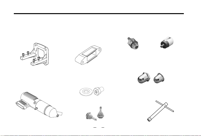
O.S. GENUINE PARTS & ACCESSORIES
RADIAL MOTOR MOUNT
■
(71906200) for 40,46LA
(71905200) for 65LA
SUPER SILENCER
■
E-3030S
E-4010S
(23325030) for 40,46LA
(26028010) for 65LA
SILENCER EXTENSION
■
ADAPTORS
(23325100) for 40,46LA
(26625340) for 65LA
LONG PROPELLER NUT SET
■
(73101000) for 40~46LA
(73101010) for 65LA
BUBBLESS WEIGHT
■
(Bubble Eliminating Tank Weight)
(71531000)
29
GLOW PLUG
■
(71605300)
A3
SPINNER NUT
■
1
/
4
5
/
16
LONG SOCKET WRENCH
■
WITH PLUG GRIP
(71521000)
SUPER FILTER (L
■
(72403050)
(23024009) for 40,46LA
"-28(L)
(45024000) for 65LA
"-24
)
Page 31

EXPLODED VIEW
N.+M3X12
1
(
MAX-40LA
2
)
r
30
5
N.+M3.5X5
7
6
✽
Type of screw C…Cap Screw M…Oval Fillister-Head Screw
3
4
5
-1
5
-2
0
9
8
F…Flat Head Screw N…Round Head Screw S…Set Screw
-
=
N.+M3X8
e
S.3X3
w
w
w
w
-5
w
-6
q
-4
w
-3
-2
w
-1
Page 32

ENGINE PARTS LIST
Description
1
Cylinder Head
2
Cylinder & Piston Assembly
3
Piston Pin
4
Connecting Rod
5
Carburettor Complete (40D)
5
Carburettor Gasket
-1
5
Carburettor Retaining Screw
-2
6
Propeller Nut
7
Propeller Washer
8
Drive Hub
9
Thrust Washer
0
31
Crankcase
-
Gasket Set
=
Crankshaft
q
Cover Plate
w
Needle Valve Assembly
w
Needle
-1
w
"O" Ring(2pcs.)
-2
w
Set Screw
-3
w
Ratchet Spring
-4
w
Needle Valve Body
-5
w
Needle Valve Body Retaining Screw
-6
e
Needle Valve Assembly Bracket
r
Screw Set
E-3030 Silencer
Exhaust Pressure Nipple
Assembly Screw
Retaining
Specifications are subject to alteration for improvement without notice.
Screw
(2pcs.)
(MAX-40LA)
Midnight Blue
Code No.
2 4004 000 2 4004 010
2 4003 010
2 3356 000
2 4005 000
2 4081 000
2 2615 000
2 3081 706
2 3210 007
2 4009 000
2 4008 000
2 2020 001
2 4001 001 2 4001 011
2 3364 000
2 3302 000
2 4007 110
2 6582 900
2 4081 970
2 4981 837
2 6381 501
2 6711 305
2 6582 910
2 6582 920
2 4007 120
2 4013 000
2 3325 020
2 2681 957
2 3325 320
2 2625 404
Natural
Page 33

EXPLODED VIEW
N.+M3X12
1
(
MAX-46LA
2
)
r
32
5
N.+M3.5X5
7
6
✽
Type of screw C…Cap Screw M…Oval Fillister-Head Screw
3
4
5
-1
5
-2
0
9
8
F…Flat Head Screw N…Round Head Screw S…Set Screw
-
=
N.+M3X8
e
S.3X3
w
w
w
w
-5
w
-6
q
-4
w
-3
-2
w
-1
Page 34

ENGINE PARTS LIST
(MAX-46LA)
Description
1
Cylinder Head
2
Cylinder & Piston Assembly
3
Piston Pin
4
Connecting Rod
5
Carburettor Complete (40D)
5
Carburettor Gasket
-1
5
Carburettor Retaining Screw
-2
6
Propeller Nut
7
Propeller Washer
8
Drive Hub
9
Thrust Washer
0
Crankcase
33
-
Gasket Set
=
Crankshaft
q
Cover Plate
w
Needle Valve Assembly
w
Needle
-1
w
"O" Ring(2pcs.)
-2
w
Set Screw
-3
w
Ratchet Spring
-4
w
Needle Valve Body
-5
w
Needle Valve Body Retaining Screw
-6
e
Needle Valve Assembly Bracket
r
Screw Set
E-3030 Silencer
Exhaust Pressure Nipple
Assembly Screw
Retaining
Specifications are subject to alteration for improvement without notice.
Screw
(2pcs.)
Code No.
2 4004 100
2 4003 100
4 5806 000
2 4005 000
2 4081 000
2 2615 000
2 3081 706
2 3210 007
2 4009 000
2 4008 000
2 2020 001
2 4001 100
2 4014 100
2 3302 000
2 4007 110
2 6582 900
2 4081 970
2 4981 837
2 6381 501
2 6711 305
2 6582 910
2 6582 920
2 4007 120
2 4013 000
2 3325 020
2 2681 957
2 3325 320
2 2625 404
Page 35

EXPLODED VIEW
N.+M3X18
1
1
-1
2
(
MAX-65LA
)
e
34
3
4
5
-1
5
5
-2
N.+M3.5X6
0
9
8
7
6
✽
Type of screw C…Cap Screw M…Oval Fillister-Head Screw
F…Flat Head Screw N…Round Head Screw S…Set Screw
S.3X3
-
w
-3
q
=
w
N.+M3X12
w
-1
-2
w
-4
w
w
-5
w
-6
Page 36

ENGINE PARTS LIST
(MAX-65LA)
Code No.
1
2 6504 000
1
35
Specifications are subject to alteration for improvement without notice.
2 6021 110
-1
2 6503 000
2
4 5606 000
3
2 6025 000
4
2 6581 000
5
4 6215 000
5
-1
2 5081 700
5
-2
4 5010 002
6
2 8009 002
7
2 6508 000
8
2 6022 200
9
2 6501 000
0
2 6022 000
-
2 6507 000
=
2 6582 930
q
2 6582 900
w
2 4081 970
w
-1
2 4981 837
w
-2
2 6381 501
w
-3
2 6711 305
w
-4
2 6582 910
w
-5
2 6582 920
w
-6
2 6513 000
e
7 1605 300
2 6028 000
2 2681 953
2 6028 100
2 6625 210
Cylinder Head
Head Gasket
Cylinder & Piston Assembly
Piston Pin
Connecting Rod
Carburettor Complete(60J)
Carburettor Gasket
Carburettor Retauning Screw(2pcs.)
Propeller Nut
Propeller Washer
Drive Hub
Thrust Washer
Crankcase
Crankshaft
Cover Plate
Needle Valve Assembly Bracket
Needle Valve Assembly
Needle Valve Body
Screw Set
Glow Plug A3
Silencer(E-4010)
Description
Needle
"O"Ring(2pcs.)
Set Screw
Ratchet Spring
Needle Valve Body Retaining Screw
Exhaust Pressure Nipple
Assembly Screw
Retaining Screw(2pcs.)
Page 37

CARBURETTOR EXPLODED VIEW & PARTS LIST
TYPE 40D
N.+M3X6
1
- 1
1
✽
Type of screw
C…Cap Screw M…Oval Fillister-Head Screw
F…Flat Head Screw N…Round Head Screw S…Set Screw
Code No.
1
2 2081 408
-1
1
2 2081 313
2
2 4081 200
3
2 4081 600
4
2 4081 100
5
2 4081 300
6
2 2615 000
7
2 3081 706
N.+M2.6X15
4
3
2
N.+M3.5X5
6
Description
Throttle Lever Assembly
Throttle Lever Retaining Screw
Carburettor Rotor
Airbleed Screw
Carburettor Body
Throttle Stop Screw
Carburettor Gasket
Carburettor Retaining Screw
5
N.+M2.6X6
7
1
1
2
3
4
5
6
7
8
Specifications are subject to alteration for improvement without notice.
N.+M3X6
-1
1
1
-1
C.M2.6X18
Code No.
2 2081 408
2 2081 313
2 6581 200
2 6029 500
2 6581 100
2 2826 131
2 6029 430
4 6215 000
2 5081 700
36
TYPE 60J
2
5
4
6
3
7
8
Description
Throttle Lever Assembly
Throttle Lever Retaining Screw
Carburettor Rotor
Air-bleed Screw
Carburettor Body
Throttle Stop Screw
Nozzle For Remote Needle Valve
Carburettor Rubber Gasket
Carburettor Retaining Screw
N.+M3.5X6
Page 38
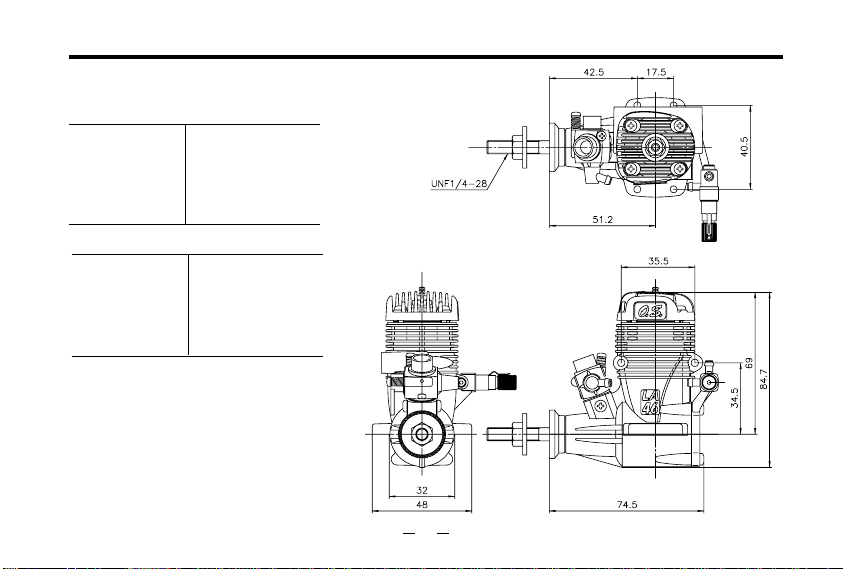
MAX-40LA/46LA THREE VIEW DRAWING
40LA SPECIFICATIONS
Displacement
■
Bore
■
Stroke
■
Practical R.P.M.
■
Power output
■
Weight
■
6.49 cc (0.396cu.in.
21.2 mm (0.835in.
18.4 mm (0.724in.
~
2,000
1.0 bhp / 15,000 r.p.m.
269g (9.5oz.
46LA SPECIFICATIONS
Displacement
■
Bore
■
Stroke
■
Practical R.P.M.
■
Power output
■
Weight
■
7.64 cc (0.467cu.in.
23.0 mm (0.906in.
18.4 mm (0.724in.
~
2,000
1.2 bhp / 15,000 r.p.m.
272g (9.6oz.
16,000 r.p.m.
)
16,000 r.p.m.
)
Dimensions(mm)
)
)
)
)
)
)
37
Page 39

MAX-65LA THREE VIEW DRAWING
Dimensions(mm)
65LA SPECIFICATIONS
Displacement
■
Bore
■
Stroke
■
Practical R.P.M.
■
Power output
■
Weight
■
10.85 cc (0.662cu.in.
24.0 mm (0.945 in.
24.0 mm (0.945 in.
~
16,000 r.p.m.
2,000
1.7 bhp / 16,000 r.p.m.
535 g (18.87 oz.
)
)
)
)
UNF5/16-24
25
52
64
31
35.6
42
85.4
107
43.8
42
62
91.2
38
Page 40

E
C
R
I
P
S
I
Y
O
T
I
N
L
A
U
Q
D
E
L
L
A
U
Q
E
N
U
&
P
E
R
F
O
R
M
A
N
C
E
E
S
T
A
B
L
I
S
H
I
N
G
T
H
E
R
S
A
T
D
A
N
C
Copyright 2000 by O.S.Engines Mfg. Co., Ltd. All rights reserved. Printed in Japan.
E
C
N
E
L
L
E
C
X
E
F
O
S
D
6-15 3-Chome Imagawa Higashisumiyoshi-ku
Osaka 546-0003, Japan
TEL. (06) 6702-0225
FAX. (06) 6704-2722
URL : http://www.os-engines.co.jp
110102
 Loading...