

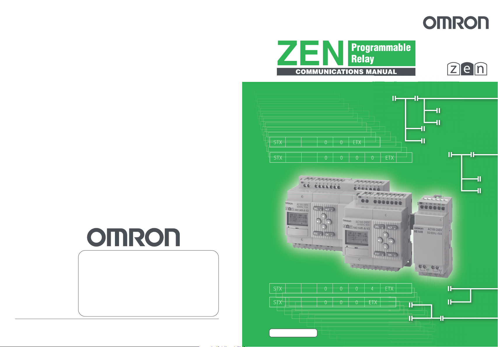
Omron ZEN Communications Manual
Authorized Distributor:
Man. No. Z212-E1-01 Note: Specifications subject to change without notice. Printed in Japan
0206-?M(0206
(?)
Man. No. Z212-E1-01

Preface
OMRON products are manufactured for use according to proper procedures by a qualified operator and
only for the purposes described in this manual.
The ZEN is a compact and highly functional controller that can be used to easily automate small-scale
applications. Its development has drawn on OMRON's advanced control technology and expertise in
manufacturing various types of controllers.
Version 2 of the ZEN includes Economy-type CPU Units and Communications-type CPU Units. Twin timer
operation and operation between days for weekly timers have been added. Pulse output operation and 8digit counters with high-speed counting have also been added, and Expansion I/O Units have been
downsized to half the width.
This manual describes the communications functions of Communications-type CPU Units. When using a
Communications-type CPU Unit, read this manual and be sure to use the communications functions
correctly. Keep the manual close at hand so that you can refer to it whenever necessary.
● Intended Audience
This manual is intended for the following readers.
• Persons in charge of introducing FA devices
• Persons who design FA systems
• Persons who install or connect FA devices
• Persons who manage working FA installations
Persons who use this product must have sufficient knowledge of electrical systems (i.e., an electrical
engineer or the equivalent).
ii

Warranty and Application Considerations
Read and Understand this Manual
Please read and understand this manual before using the product. Please consult your OMRON
representative if you have any questions or comments.
Warranty and Limitations of Liability
Warranty and Limitations of Liability
WARRANTY
OMRON's exclusive warranty is that the products are free from defects in materials and
workmanship for a period of one year (or other period if specified) from date of sale by OMRON.
OMRON MAKES NO WARRANTY OR REPRESENTATION, EXPRESS OR IMPLIED,
REGARDING NON-INFRINGEMENT, MERCHANTABILITY, OR FITNESS FOR PARTICULAR
PURPOSE OF THE PRODUCTS. ANY BUYER OR USER ACKNOWLEDGES THAT THE
BUYER OR USER ALONE HAS DETERMINED THAT THE PRODUCTS WILL SUITABLY MEET
THE REQUIREMENTS OF THEIR INTENDED USE. OMRON DISCLAIMS ALL OTHER
WARRANTIES, EXPRESS OR IMPLIED.
LIMITATIONS OF LIABILITY
OMRON SHALL NOT BE RESPONSIBLE FOR SPECIAL, INDIRECT, OR CONSEQUENTIAL
DAMAGES, LOSS OF PROFITS OR COMMERCIAL LOSS IN ANY WAY CONNECTED WITH
THE PRODUCTS, WHETHER SUCH CLAIM IS BASED ON CONTRACT, WARRANTY,
NEGLIGENCE, OR STRICT LIABILITY.
In no event shall the responsibility of OMRON for any act exceed the individual price of the
product on which liability is asserted.
IN NO EVENT SHALL OMRON BE RESPONSIBLE FOR WARRANTY, REPAIR, OR OTHER
CLAIMS REGARDING THE PRODUCTS UNLESS OMRON'S ANALYSIS CONFIRMS THAT
THE PRODUCTS WERE PROPERLY HANDLED, STORED, INSTALLED, AND MAINTAINED
AND NOT SUBJECT TO CONTAMINATION, ABUSE, MISUSE, OR INAPPROPRIATE
MODIFICATION OR REPAIR.
iii

Application Consideration
SUITABILITY FOR USE
THE PRODUCTS CONTAINED IN THIS DOCUMENT ARE NOT SAFETY RATED. THEY ARE
NOT DESIGNED OR RATED FOR ENSURING SAFETY OF PERSONS, AND SHOULD NOT BE
RELIED UPON AS A SAFETY COMPONENT OR PROTECTIVE DEVICE FOR SUCH
PURPOSES. Please refer to separate catalogs for OMRON's safety rated products.
OMRON shall not be responsible for conformity with any standards, codes, or regulations that
apply to the combination of products in the customer’s application or use of the product.
At the customer’s request, OMRON will provide applicable third party certification documents
identifying ratings and limitations of use that apply to the products. This information by itself is not
sufficient for a complete determination of the suitability of the products in combination with the
end product, machine, system, or other application or use.
The following are some examples of applications for which particular attention must be given.
This is not intended to be an exhaustive list of all possible uses of the products, nor is it intended
to imply that the uses listed may be suitable for the products:
• Outdoor use, uses involving potential chemical contamination or electrical interference, or
conditions or uses not described in this document.
• Nuclear energy control systems, combustion systems, railroad systems, aviation systems,
medical equipment, amusement machines, vehicles, safety equipment, and installations subject
to separate industry or government regulations.
• Systems, machines, and equipment that could present a risk to life or property.
Please know and observe all prohibitions of use applicable to the products.
NEVER USE THE PRODUCTS FOR AN APPLICATION INVOLVING SERIOUS RISK TO LIFE
OR PROPERTY WITHOUT ENSURING THAT THE SYSTEM AS A WHOLE HAS BEEN
DESIGNED TO ADDRESS THE RISKS, AND THAT THE OMRON PRODUCT IS PROPERLY
RATED AND INSTALLED FOR THE INTENDED USE WITHIN THE OVERALL EQUIPMENT OR
SYSTEM.
iv

Disclaimers
Disclaimers
CHANGE IN SPECIFICATIONS
Product specifications and accessories may be changed at any time based on improvements and
other reasons.
It is our practice to change model numbers when published ratings or features are changed, or
when significant construction changes are made. However, some specifications of the products
may be changed without any notice. When in doubt, special model numbers may be assigned to
fix or establish key specifications for your application on your request. Please consult with your
OMRON representative at any time to confirm actual specifications of purchased products.
DIMENSIONS AND WEIGHTS
Dimensions and weights are nominal and are not to be used for manufacturing purposes, even
when tolerances are shown.
PERFORMANCE DATA
Performance data given in this manual is provided as a guide for the user in determining
suitability and does not constitute a warranty. It may represent the result of OMRON's test
conditions, and the users must correlate it to actual application requirements. Actual performance
is subject to the OMRON Warranty and Limitations of Liability.
ERRORS AND OMISSIONS
The information in this document has been carefully checked and is believed to be accurate;
however, no responsibility is assumed for clerical, typographical, or proofreading errors, or
omissions.
Copyright and Copy Permission
Copyright and Copy Permission
COPYRIGHT AND COPY PERMISSION
This document shall not be copied for sales or promotions without permission.
This document is protected by copyright and is intended solely for use in conjunction with the
product. Please notify us before copying or reproducing this document in any manner, for any
other purpose. If copying or transmitting this document to another, please copy or transmit it in its
entirety.
v


Precautions
This section provides precautions for using the ZEN Programmable Relays.
This information contained in this section is important for the safe and reliable application of the ZEN. You must read
this section and understand the information before attempting to set up for a ZEN.
Safety Precautions . . . . . . . . . . . . . . . . . . . . . . . . . . . . . . . . . . . . . . . . . . . . . .viii
Precautions for Safe Use . . . . . . . . . . . . . . . . . . . . . . . . . . . . . . . . . . . . . . . . . x
Precautions for Correct Use . . . . . . . . . . . . . . . . . . . . . . . . . . . . . . . . . . . . . .xii
vii
Precautions
Safety Precautions
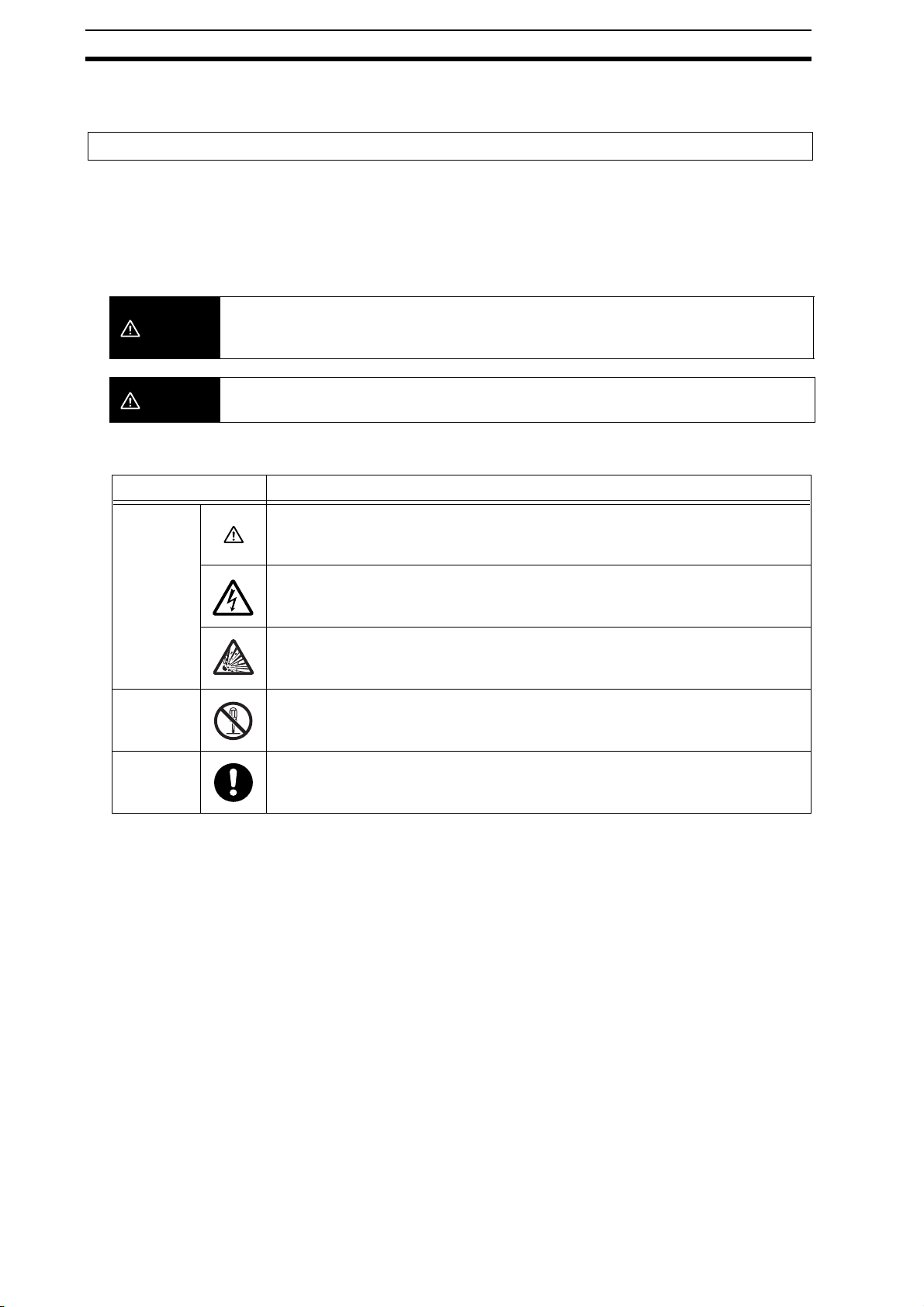
Definition of Precautionary Information
The following notation is used in this manual to provide precautions required to ensure safe usage of the product.
The safety precautions that are provided are extremely important to safety. Always read and heed the information
provided in all safety precautions.
The following notation is used.
Indicates a potentially hazardous situation which, if not avoided, will result in minor or
WARNING
moderate injury, or may result in serious injury or death. Additionally, there may be significant
property damage.
CAUTION
Symbols
Caution
Prohibition
Mandatory
Caution
Indicates a potentially hazardous situation which, if not avoided, may result in minor or
moderate injury or in property damage.
Symbol Meaning
General Caution
Indicates non-specific general cautions, warnings, and dangers.
Electrical Shock Caution
Indicates possibility of electric shock under specific conditions.
Explosion Caution
Indicates possibility of explosion under specific conditions.
Disassembly Prohibition
Indicates prohibitions when there is a possibility of injury, such as from electric shock,
as the result of disassembly.
General Caution
Indicates non-specific general cautions, warnings, and dangers.
viii
Precautions
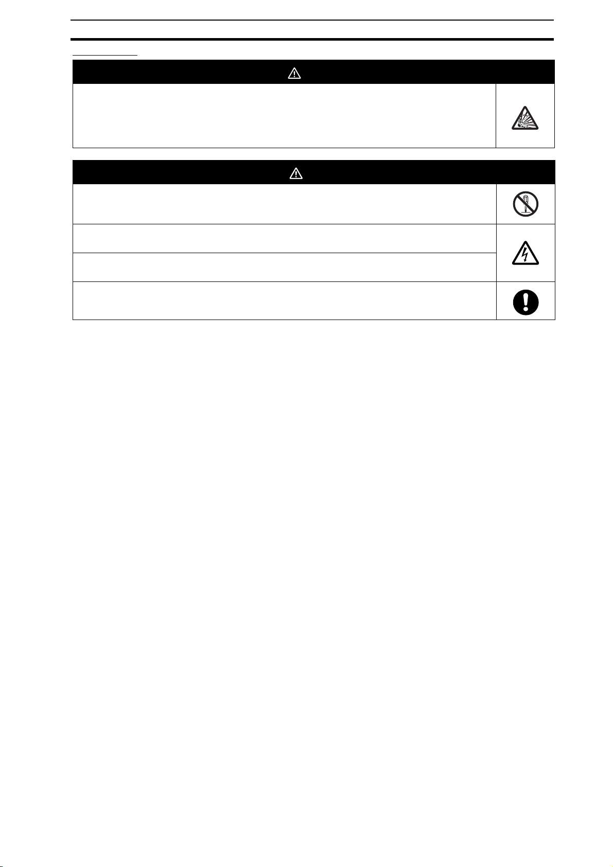
WARNIN G
Serious human hazard may occasionally occur due to ignition or rupture of the lithium battery used in
the Battery Unit. Do not short the battery terminals or charge, disassemble, deform under pressure,
or incinerate the battery.
Never use any battery that has been dropped on the floor or otherwise
subjected to excessive shock.
CAUTION
Electric shock, fire, or malfunction may occur. Do not disassemble, modify, or repair the ZEN or touch
any of the internal parts.
Electrical shock may occur. Never touch the I/O terminals, computer connector, Expansion Unit
connector, or Battery Unit connector while power is being supplied.
Electrical shock may occur. Do not remove the Expansion Unit connector cover unless an Expansion
I/O Unit will be permanently installed.
Fires may occasionally occur. Tighten the terminal block screws to the specified torque (0.5 to 0.6
N·m) so that they do not become loose.
Precautions
ix

Precautions
Precautions for Safe Use
Please observe the following precautions for safe use of this products.
Circuit Design
1. All interface connectors and battery connector are live parts, they may not be directly connected to Softy Extra
Low Voltage (SELV) circuit or to accessible conductive parts.
For the programming units and Personal Computers use only the ZEN-CIF01 Connecting Cable (optional
accessory) manufactured by OMRON.
ZEN-CIF01 provides safe (reinforced) insulation between Personal Computers and ZEN.
2. Provide emergency stop circuits, external interlock circuits, limit circuits, and other safety circuits in addition to
any provided within the ZEN control circuits to ensure safety of the overall system in the event of ZEN failure or
external factors.
3. If the ZEN discovers an error during self-diagnosis, operation will be stopped and all outputs will be turned OFF.
As a countermeasure for such problems, external safety measures must be provided to ensure safety in the
overall system.
4. Outputs from the ZEN may remain ON or OFF due to faults in internal circuits such as output relay fusing or
burning, or output transistor destruction. As a countermeasure for such problems, external safety measures
must be provided to ensure safety in the overall system.
5. Fail-safe measures must be taken by the user to ensure overall system safety in the event of broken signal lines
or momentary power interruptions.
6. The durability of the output relays is largely affected by the switching conditions. Confirm the operation of the
system under actual operating conditions and set the switching frequency to ensure that adequate performance
will be provided. Insulation faults and burning in the ZEN may result if relays are used after their performance
has deteriorated.
Connecting Expansion I/O Units
1. Supply power to both the CPU Unit and Expansion I/O Units from the same power supply and turn them ON
and OFF at the same time.
2. When connecting Expansion I/O Units with DC inputs to a CPU Unit with an AC power supply, the burst noise
immunity will be 1 kV (IEC 61000-4-4).
3. Expansion I/O Units with AC inputs (ZEN-8E1AR) cannot be connected to a CPU Unit with a DC power supply.
System Startup and Program Changes
1. Check the user program for proper execution before actually running it on the Unit.
2. Disconnect the output lines from the system before testing operation in any system in which incorrect operation
can result in injury or equipment damage.
3. Confirm safety before attempting any of the following operations.
• Changing the operating mode (RUN/STOP).
• Using the button switches.
• Changing bit status or parameter settings.
4. Double-check all wiring before turning ON the power supply.
5. Refer to Cycle Time Calculation Method on page 130 in the ZEN Programmable Relay Operation Manual (Cat.
No. Z211) and confirm that the increase in the cycle time will not affect operation. If the cycle time is too long,
it may become impossible to read input signals accurately. The increase in the cycle time will be particularly
noticeable when set values are written in RUN mode for a CPU Unit with communications (ZEN-10C4@R-@-
V2).
Installation and Wiring
1. Do not allow the ZEN to fall during installation.
2. Be sure that the DIN Track mounting levers, Expansion I/O Units, Memory Cassettes, Battery Units, cable
connectors, and other items with locking devices are properly locked into place. Improper locking may result in
malfunction.
3. When mounting the ZEN to the surface of the control panel, tighten mounting screws to the following torques.
CPU Units: 1.03 N⋅m max.
Expansion I/O Units: 0.46 N⋅m max.
4. Use wires with cross-sectional areas of 0.2 to 2.5 mm
them for 6.5 mm. If using stranded wires, always connect straight crimp terminals (0.25 to 2.5 mm
Handling
1. The environment of use of ZEN is “Pollution degree 2” and “Overvoltage category II” specified in IEC60664-1.
2
(equivalent to AWG24 to AWG14) for wiring and strip
2
).
x

Precautions
2. Always use the ZEN within the rated ambient operating temperature and humidity. The rated ambient operating
temperature is 0 to 55°C for LCD-type CPU Units and –25 to 55°C for LED-type CPU Units. If the ZEN is used
near sources of heat, such as a power supply, the internal temperature of the ZEN may increase, lowering the
durability of the ZEN.
3. Discharge static electricity from your body, e.g., by touching a grounded metal plate, before touching any Unit.
4. The exterior of the Units will be damaged if it comes into contact with organic solvents (e.g., benzene or paint
thinner), strong alkalies, or strong acids. Never allow such substances to come into contact with the Units.
5. Do not apply voltages exceeding the rated voltages. Internal elements may be destroyed.
6. Short failures or open failures may result from the destruction of output elements. Do not use loads that exceed
the rated output current.
Maintenance
When replacing a CPU Unit, transfer to the new Unit and confirm all settings for clock data, internal holding bits,
holding timers, and counters before starting operation again.
Transportation and Storage
1. Use special packaging boxes when transporting the ZEN and do not subject it to excessive shock or vibration
or drop it during shipment.
2. Store the ZEN at an ambient temperature of −40 to 75°C for LED-type CPU Units and −20 to 75°C for all other
types of CPU Units. If the ZEN has been stored at −10°C or lower, allow it to stand at room temperature for 3
hours or longer before turning ON the power supply.
xi

Precautions
Precautions for Correct Use
Installation Environment
1. Do not install the ZEN in the following locations.
• Locations subject to radical changes in temperature
• Location with high humidity subject to condensation
• Locations subject to excessive dust or dirt
• Locations subject to corrosive gas
• Locations subject to direct sunlight
2. Do not install the ZEN in locations subject to shock or vibration. Extended use in such location may cause
damage from stress.
3. In environments subject to static electricity (e.g., close to pipes conveying forming materials, powders, or fluid
materials), separate the ZEN as far as possible from the source of static electricity.
4. The ZEN is neither waterproof nor oil-proof. Do not use it in locations subject to water or oil.
5. Use the ZEN within the allowable power supply voltage range. Be particularly careful in locations with bad power
supply conditions, e.g., large fluctuations in the power supply voltage.
6. Do not install the ZEN in locations subject to excessive noise, which may cause the ZEN to fail.
7. Take appropriate and sufficient countermeasures when installing systems in the following locations:
• Locations subject to strong electromagnetic fields
• Locations subject to possible exposure to radioactivity
Power Supply
1. Always turn OFF the power supply to the ZEN (CPU Unit and Expansion I/O Units) before attempting any of the
following.
• Assembling the ZEN
• Attaching or removing Expansion I/O Units
• Connecting or disconnecting any cables or wiring
• Attaching or removing the Memory Cassette
• Attaching or removing the Battery Unit
2. If the power supply is interrupted for 2 days or more (at 25°C), the internal capacitor will discharge and internal
bit status and the contents of PV areas will be lost or corrupted and dates and times will be reset. When
restarting operation after the power supply has been interrupted for an extended period of time, check the
system in advance to confirm that no errors will occur.
Handling
1. Connect connectors only after confirming that the direction or polarity is correct.
2. Failures could result if dust or dirt enters the ZEN. Always connect the connector cover to the computer
connector whenever it is not being used.
3. Do not remove the label from the left side of the CPU Unit if a Battery Unit is not mounted.
EEPROM Write Life
The EEPROM has a limited write life. The write life may be exceeded if communications are used frequently to
write settings. Consider this in the system design.
Other
1. The execution of the ladder program in the ZEN is different from that for other PLCs. Refer to Appendix B Ladder
Program Execution in the ZEN Programmable Relay Operation Manual (Cat. No. Z211) when writing the ladder
program.
2. Abide by all local ordinances and regulations when disposing of the ZEN.
3. The Battery Unit (ZEN-BAT01, sold separately) contains a lithium battery. Observe all applicable legal
requirements for your area when disposing of the lithium battery.
xii

Conventions Used in This Manual
This user's manual describes the communications functions of CPU Units with communications. For information on using other functions, refer to the ZEN Programma-
ble Relay Operation Manual.
■ Manual Contents
Item Description
SECTION 1
Communications Methods
SECTION 2
CompoWay/F
Communications Protocol
SECTION 3
Communications Data
Appendix ASCII list
■ Related Manuals
ZEN Programmable Relay Operation Manual (Z211)
ZEN Support Software Operation Manual (Z184)
This section briefly describes the supported
communications methods and how to wire
equipment. Refer to this section before setting up equipment.
This section describes the protocol for
communications using the CompoWay/F
format.
This section lists the details of the
communications data in the CompoWay/F
communications protocol.
xiii

Revision History
■ Manual Revision Code
A manual revision code appears as a suffix to the catalog number on the front and
back cover of the manual.
Man. No. Z212-E1-01
■ Revision History
The following table outlines the changes made to the manual during each revision.
Page numbers refer to the previous version.
Revision code Date Revised content
01 January 2006 Original production
xiv

Table of Contents
Precautions vii
SECTION 1
Communications Methods
1.1 Overview of Communications Methods ......................................................... 2
Introduction ............................................................................................ 2
Communications Specifications ............................................................. 2
Transmission Procedure ........................................................................ 3
Interface ................................................................................................. 3
Wiring ..................................................................................................... 3
Communications Parameters ................................................................. 4
Setting Communications Parameters .................................................... 5
SECTION 2
CompoWay/F Communications Protocol
2.1 Data Format ................................................................................................ 10
Command Frame ................................................................................. 10
Response Frame ................................................................................. 11
Communications Data .......................................................................... 12
2.2 Structure of Command Text ........................................................................ 14
PDU Structure ...................................................................................... 14
Addresses ............................................................................................ 14
Number of Elements ............................................................................ 14
List of Services ..................................................................................... 15
2.3 Detailed Description of the Services ........................................................... 16
Read Variable Area .............................................................................. 16
Variable Type and Read Start Address ............................................... 16
Bit Position ........................................................................................... 16
Number of Elements ............................................................................ 16
Response Code ................................................................................... 16
Reading Timers, Counters, and Comparators ..................................... 17
Reading Work Bits and HR Bits ........................................................... 20
Write Variable Area .............................................................................. 21
Writing Timer and Counter Set Values ................................................ 22
Writing Work Bits and HR Bits ............................................................. 26
Read Controller Attributes .................................................................... 26
Read Controller Status ......................................................................... 27
Read Time Data ................................................................................... 28
Write Time Data ................................................................................... 29
Echoback Test ..................................................................................... 31
Operation Command ............................................................................ 32
2.4 Response Code List .................................................................................... 34
SECTION 3
Communications Data
3.1 Variable Area (Data Range) List ................................................................. 36
Appendix 41
ASCII List .............................................................................................................. 42
Preface - - - - - - - - - - - - - - - - - - - - - - - - - - - - - ii
Warranty and Application Considerations - - - - - iii
Conventions Used in This Manual - - - - - - - - - - xiii
Revision History - - - - - - - - - - - - - - - - - - - - - - xiv
xv

xvi

SECTION 1 Communications Methods
This section briefly describes the supported communications methods and
how to wire equipment. Refer to this section when setting up equipment.
1.1 Overview of Communications Methods ........................... 2
Introduction................................................................. 2
Communications Specifications.................................. 2
Transmission Procedure............................................. 3
Interface...................................................................... 3
Wiring ......................................................................... 3
Communications Parameters ..................................... 4
Setting Communications Parameters ......................... 5
1

Overview
SECTION 1 Communications Methods
1.1 Overview of Communications Methods
■ Introduction
A host computer (see note 1) can communicate with the ZEN using the
CompoWay/F communications protocol. The host computer is
programmed to monitor and set ZEN settings. This manual is thus
written from the viewpoint of the host computer. Up to 32 nodes
including host computers can be connected via CompoWay/F.
CompoWay/F is an integrated protocol for OMRON general-purpose
serial communications. Consistent frame formats and commands that
are compliant with FINS (see note 2), which is widely used with
OMRON Programmable Controllers (PLCs), enable easy communications between a host computer and components.
Note 1:Host computers include personal computers.
Note 2:FINS (Factory Interface Network Service) is a message service
used between controllers on OMRON FA networks.
The ZEN supports the following communications functions.
• Reading/writing of parameters
• Operation instructions
Note: RS-485 communications are not possible when a computer
running ZEN Support Software is online with the CPU Unit.
■Communications Specifications
Item Details Default settings
Transmission line connection Multi-drop None
Communications method RS-485 (2-wire, half-duplex) None
Synchronization method Start-stop synchronization None
Communications baud rate 4800, 9600, or 19200 bps 9600 bps
Communications code ASCII None
Communications data bits 7 or 8 bits 7 bits
Communications stop bits 1 or 2 bits 2 bits
Error detection Vertical parity (none, even, or odd) Even
BCC (Block Check Character) None
Flow control None ---
Interface RS-485 ---
Retry function None ---
Communications buffer 36 bytes ---
Communications protocol CompoWay/F None
Number of nodes 1:1 connection:
1:N connections:
1 node
None
32 nodes max. including host computer
2
 Loading...