


 Loading...
Displacement Sensor
ZW-8000/7000/5000 series
Confocal Fiber Type
Displacement Sensor
User’s Manual for Communications Settings
ZW-8000@
ZW-7000@
ZW-5000@
Z363-E1-06

Introduction
Thank you for purchasing the ZW-8000/7000/5000 Series.
This manual provides information regarding functions, performance and operating methods that are required for using the ZW-8000/7000/5000 Series.
When using the ZW-8000/7000/5000 Series, be sure to observe the following:
•The ZW-8000/7000/5000 Series must be operated by personnel knowledgeable in electrical engineering.
•To ensure correct use, please read this manual thoroughly to deepen your understanding of the product.
•Please keep this manual in a safe place so that it can be referred to whenever necessary.

User’s Manual for Communications Settings
Confocal Fiber Type
Displacement Sensor
ZW-8000/7000/5000 Series
Terms and Conditions Agreement
(Please Read)
Overview of Communication Specifica- |
1 |
tions |
|
|
|
|
|
Parallel I/O Connection |
2 |
|
|
|
|
EtherCAT Connection |
3 |
|
|
|
|
EtherNet/IP Connection |
4 |
|
|
|
|
No-protocol Connection |
5 |
|
|
|
|
Sensor Controller Operations |
6 |
|
|
|
|
Troubleshooting |
7 |
|
|
|
|
Appendices |
8 |
|
|

Terms and Conditions Agreement
Read and understand this Manual
Please read and understand this catalog before purchasing the products. Please consult your OMRON representative if you have any questions or comments.
Warranties
• Exclusive Warranty
Omron’s exclusive warranty is that the Products will be free from defects in materials and workmanship for a period of twelve months from the date of sale by Omron (or such other period expressed in writing by Omron). Omron disclaims all other warranties, express or implied.
• Limitations
OMRON MAKES NO WARRANTY OR REPRESENTATION, EXPRESS OR IMPLIED, ABOUT NONINFRINGEMENT, MERCHANTABILITY OR FITNESS FOR A PARTICULAR PURPOSE OF THE PRODUCTS. BUYER ACKNOWLEDGES THAT IT ALONE HAS DETERMINED THAT THE PRODUCTS WILL SUITABLY MEET THE REQUIREMENTS OF THEIR INTENDED USE.
Omron further disclaims all warranties and responsibility of any type for claims or expenses based on infringement by the Products or otherwise of any intellectual property right. (c) Buyer Remedy. Omron’s sole obligation hereunder shall be, at Omron’s election, to (i) replace (in the form originally shipped with Buyer responsible for labor charges for removal or replacement thereof) the
non-complying Product, (ii) repair the non-complying Product, or (iii) repay or credit Buyer an amount equal to the purchase price of the non-complying Product; provided that in no event shall Omron be responsible for warranty, repair, indemnity or any other claims or expenses regarding the Products unless Omron’s analysis confirms that the Products were properly handled, stored, installed and maintained and not subject to contamination, abuse, misuse or inappropriate modification. Return of any Products by Buyer must be approved in writing by Omron before shipment. Omron Companies shall not be liable for the suitability or unsuitability or the results from the use of Products in combination with any electrical or electronic components, circuits, system assemblies or any other materials or substances or environments. Any advice, recommendations or information given orally or in writing, are not to be construed as an amendment or addition to the above warranty.
See http://www.omron.com/global/ or contact your Omron representative for published information.
Limitation on Liability; Etc.
OMRON COMPANIES SHALL NOT BE LIABLE FOR SPECIAL, INDIRECT, INCIDENTAL, OR CONSEQUENTIAL DAMAGES, LOSS OF PROFITS OR PRODUCTION OR COMMERCIAL LOSS IN ANY WAY CONNECTED WITH THE PRODUCTS, WHETHER SUCH CLAIM IS BASED IN CONTRACT, WARRANTY, NEGLIGENCE OR STRICT LIABILITY.
Further, in no event shall liability of Omron Companies exceed the individual price of the Product on which liability is asserted.
Suitability of Use
Omron Companies shall not be responsible for conformity with any standards, codes or regulations which apply to the combination of the Product in the Buyer’s application or use of the Product. At Buyer’s request, Omron will provide applicable third party certification documents identifying ratings and limitations of use which apply to the Product. This information by itself is not sufficient for a complete determination of the suitability of the Product in combination with the end product, machine, system, or other application or use. Buyer shall be solely responsible for determining appropriateness of the particular Product with respect to Buyer’s application, product or system. Buyer shall take application responsibility in all cases.
NEVER USE THE PRODUCT FOR AN APPLICATION INVOLVING SERIOUS RISK TO LIFE OR PROPERTY
2
ZW-8000/7000/5000 User’s Manual for Communications Settings

OR IN LARGE QUANTITIES WITHOUT ENSURING THAT THE SYSTEM AS A WHOLE HAS BEEN DESIGNED TO ADDRESS THE RISKS, AND THAT THE OMRON PRODUCT(S) IS PROPERLY RATED AND INSTALLED FOR THE INTENDED USE WITHIN THE OVERALL EQUIPMENT OR SYSTEM.
Programmable Products
Omron Companies shall not be responsible for the user’s programming of a programmable Product, or any consequence thereof.
Performance Data
Data presented in Omron Company websites, catalogs and other materials is provided as a guide for the user in determining suitability and does not constitute a warranty. It may represent the result of Omron’s test conditions, and the user must correlate it to actual application requirements. Actual performance is subject to the Omron’s Warranty and Limitations of Liability.
Change in Specifications
Product specifications and accessories may be changed at any time based on improvements and other reasons. It is our practice to change part numbers when published ratings or features are changed, or when significant construction changes are made. However, some specifications of the Product may be changed without any notice. When in doubt, special part numbers may be assigned to fix or establish key specifications for your application. Please consult with your Omron’s representative at any time to confirm actual specifications of purchased Product.
Errors and Omissions
Information presented by Omron Companies has been checked and is believed to be accurate; however, no responsibility is assumed for clerical, typographical or proofreading errors or omissions.
3
ZW-8000/7000/5000
User’s Manual for Communications Settings

Precautions on Safety
For details on the precautions on safety, refer to the following manual:
 "Precautions on Safety" described in Displacement Sensor ZW-8000/7000/5000 series Confocal Fiber Type Displacement Sensor User's Manual (Z362)
Precautions for Safe Use
For details on the precautions for safe use, refer to the following manual:
 "Precautions for Safe Use" described in Displacement Sensor ZW-8000/7000/5000 series Confocal Fiber Type Displacement Sensor User's Manual (Z362)
Precautions for Correct Use
For details on the precautions for correct use, refer to the following manual:
 "Precautions for Correct Use" described in Displacement Sensor ZW-8000/7000/5000 series Confocal Fiber Type Displacement Sensor User's Manual (Z362)
Editor's Note
● Meaning of Symbols
Menu items that are displayed on the main or sub-display, and windows, dialog boxes and other GUI elements displayed on the personal computer are indicated enclosed by brackets [ ].
● Visual Aids
Indicates points that are important to achieve the full product performance, such as operational
Important
precautions.
Note |
|
Indicates application procedures. |
|
|
|
|
Indicates pages where related information can be found. |
|
|
|
|
|
Indicates that the setting is optional in a configuration procedure. |
||
Optional |
|||
Copyrights and Trademarks
•Sysmac is a trademark or registered trademark of OMRON corporation in Japan and other countries for our FA equipment products.
•Windows, Windows XP, Windows Vista, Windows 7, and Windows 8 are registered trademarks of Microsoft Corporation in the USA and other countries.
•EtherCAT→ is registered trademark and patented technology that is licensed by Beckhoff Automation GmbH, Germany.
•ODVA, CIP, CompoNet, DeviceNet, and EtherNet/IP are trademarks of ODVA.
•Microsoft product screen shots reprinted with permission from Microsoft Corporation.
•Other system names and product names that appear in this manual are the trademarks or registered trademarks of the respective companies.
4
ZW-8000/7000/5000 User’s Manual for Communications Settings

Notice
•Photocopying, duplication, or copying of all or part of this manual without permission is prohibited.
•Please understand that the specifications and other contents of this manual are subject to change for improvement without notice.
•Every effort has been made to ensure the accuracy of the contents of this manual, but if you should notice any mistake, questionable section, or the like in this manual, please contact an OMRON branch or sales office.
If you do so, please also tell us the manual number, which is found at the end of the manual.
5
ZW-8000/7000/5000
User’s Manual for Communications Settings

Relevant Manuals
The following table provides the relevant manuals for the ZW-8000/7000/5000 series Confocal Fiber Type Displacement Sensor.
Read all of the manuals that are relevant to your system configuration and application before you use the ZW8000/7000/5000 series Confocal Fiber Type Displacement Sensor.
Most operations are performed from the Sysmac Studio Automation Software. Refer to the “Sysmac Studio Version 1 Operation Manual (Cat. No. W504)” for information on the Sysmac Studio.
Purpose of use |
Manual |
|
|
ZW-8000/7000/5000 series Confocal Fiber |
ZW-8000/7000/5000 series Confocal Fiber |
|
Type Displacement Sensor User's Manual |
Type Displacement Sensor User's Manual |
|
|
for Communications Settings |
Overview of ZW-8000/7000/5000 |
● |
|
series |
|
|
|
|
|
|
|
|
Setup and Wiring |
● |
|
|
|
|
Basic Operation |
● |
|
|
|
|
Function Setting |
● |
|
|
|
|
Offline Setting |
● |
|
|
|
|
Confirm the Menu List |
● |
|
|
|
|
Connecting to the Sensor Controller |
● |
|
|
|
|
Connecting to the Sensor Controller for |
|
● |
Communication Settings |
|
|
|
|
|
|
|
|
Overview of Communication Specifica- |
|
● |
tions |
|
|
|
|
|
|
|
|
Parallel I/O |
|
● |
|
|
|
EtherCAT |
|
● |
|
|
|
EtherNet/IP |
|
● |
|
|
|
No-protocol |
|
● |
|
|
|
Specifications and External Dimen- |
● |
|
sions |
|
|
|
|
|
|
|
|
Processing Item List |
|
● |
|
|
|
System Data List |
|
● |
|
|
|
Object Dictionary |
|
● |
|
|
|
Update the Firmware |
● |
|
|
|
|
Troubleshooting |
● |
|
|
|
|
Error Messages |
|
● |
|
|
|
6
ZW-8000/7000/5000 User’s Manual for Communications Settings

Related Manuals
The related manuals are described the below tables. Please check the manuals.
Manual name |
Cat. No. |
Model numbers |
Application |
Description |
Sysmac Studio Version 1 |
W504 |
SYSMAC-SE2@@@ |
Learning about the operating |
Describes the operating proce- |
Operation Manual |
|
|
procedures and functions of |
dures of the Sysmac Studio. |
|
|
|
the Sysmac Studio. |
|
|
|
|
|
|
Confocal Fiber Type |
Z362 |
ZW-8000@ |
To learn how to set-up of Con- |
Describes how to set-up of |
Displacement Sensor |
|
ZW-7000@ |
focal Fiber Type Displacement |
Confocal Fiber Type |
ZW-8000/7000/5000 |
|
ZW-5000@ |
Sensor of ZW-8000/7000/5000 |
Displacement Sensor of ZW- |
series User's Manual |
|
|
series. |
8000/7000/5000 series. |
|
|
|
|
|
Confocal Fiber Type |
Z363 |
ZW-8000@ |
To learn how to use communi- |
Describes how to use commu- |
Displacement Sensor |
|
ZW-7000@ |
cation settings of Confocal |
nication settings of Confocal |
ZW-8000/7000/5000 |
|
ZW-5000@ |
Fiber Type |
Fiber Type |
series User's Manual for |
|
|
Displacement Sensor of ZW- |
Displacement Sensor of ZW- |
Communication Settings |
|
|
8000/7000/5000 series. |
8000/7000/5000 series. |
(This manual) |
|
|
|
|
|
|
|
|
|
7
ZW-8000/7000/5000
User’s Manual for Communications Settings

8
ZW-8000/7000/5000 User’s Manual for Communications Settings
Table of Contents
Editor's Note . . . . . . . . . . . . . . . . . . . . . . . . . . . . . . . . . . . . . . . . . . . . . . . . . . . . 4
Copyrights and Trademarks . . . . . . . . . . . . . . . . . . . . . . . . . . . . . . . . . . . . . . . . 4
Notice . . . . . . . . . . . . . . . . . . . . . . . . . . . . . . . . . . . . . . . . . . . . . . . . . . . . . . . . . 5
Relevant Manuals . . . . . . . . . . . . . . . . . . . . . . . . . . . . . . . . . . . . . . . . . . . . . . . . 6
Related Manuals . . . . . . . . . . . . . . . . . . . . . . . . . . . . . . . . . . . . . . . . . . . . . . . . . 7
1.Overview of Communication Specifications
1-1 Overview of Communication Specifications . . . . . . . . . . . . . . . . . . . 14
Overview of Communication Specifications . . . . . . . . . . . . . . . . . . . . . . . . . . . 14
1-2 Checking the System Configuration . . . . . . . . . . . . . . . . . . . . . . . . . . 15
System Configuration . . . . . . . . . . . . . . . . . . . . . . . . . . . . . . . . . . . . . . . . . . . . 16
Connection Compatibility . . . . . . . . . . . . . . . . . . . . . . . . . . . . . . . . . . . . . . . . . . 17
2.Parallel I/O Connection
2-1 Parallel I/O Connection. . . . . . . . . . . . . . . . . . . . . . . . . . . . . . . . . . . . . 20
I/O Signal Functions . . . . . . . . . . . . . . . . . . . . . . . . . . . . . . . . . . . . . . . . . . . . . 20
Settings for Parallel Input . . . . . . . . . . . . . . . . . . . . . . . . . . . . . . . . . . . . . . . . . 22
Settings for Analog Output . . . . . . . . . . . . . . . . . . . . . . . . . . . . . . . . . . . . . . . . 23
Settings for Judgment Output . . . . . . . . . . . . . . . . . . . . . . . . . . . . . . . . . . . . . . 29
Settings for Bank Control . . . . . . . . . . . . . . . . . . . . . . . . . . . . . . . . . . . . . . . . . 32
Timing Chart . . . . . . . . . . . . . . . . . . . . . . . . . . . . . . . . . . . . . . . . . . . . . . . . . . . 33
3.EtherCAT Connection
3-1 EtherCAT Connection. . . . . . . . . . . . . . . . . . . . . . . . . . . . . . . . . . . . . . 44
Overview of EtherCAT Networks . . . . . . . . . . . . . . . . . . . . . . . . . . . . . . . . . . . . 44
Communication Methods for Measurement Sensor when Connected via EtherCAT 48
Setting Communications Specifications (EtherCAT Communications) . . . . . . . 51
List of I/O Ports for Each Area (PDO Mapping) and Memory Assignments . . . 52
Timing Chart (EtherCAT) . . . . . . . . . . . . . . . . . . . . . . . . . . . . . . . . . . . . . . . . . . 75
Sample Ladder Program (EtherCAT) . . . . . . . . . . . . . . . . . . . . . . . . . . . . . . . . 85
Sysmac Device Features (EtherCAT) . . . . . . . . . . . . . . . . . . . . . . . . . . . . . . . . 86
4.EtherNet/IP Connection
4-1 EtherNet/IP Connection . . . . . . . . . . . . . . . . . . . . . . . . . . . . . . . . . . . . 90
Contents of Table
9
ZW-8000/7000/5000
User’s Manual for Communications Settings

Introduction to EtherNet/IP . . . . . . . . . . . . . . . . . . . . . . . . . . . . . . . . . . . . . . . . 90
Communication Methods for Measurement Sensor when Connected via EtherNet/
IP . . . . . . . . . . . . . . . . . . . . . . . . . . . . . . . . . . . . . . . . . . . . . . . . . . . . . . . . . . . . 92
Setting Communications Specifications (EtherNet/IP) . . . . . . . . . . . . . . . . . . . 95
Tag Data Link Setting Methods . . . . . . . . . . . . . . . . . . . . . . . . . . . . . . . . . . . . . 97
Memory Assignments and Commands . . . . . . . . . . . . . . . . . . . . . . . . . . . . . . 100
Timing Chart (EtherNet/IP) . . . . . . . . . . . . . . . . . . . . . . . . . . . . . . . . . . . . . . . 112
Sample Ladder Program (EtherNet/IP) . . . . . . . . . . . . . . . . . . . . . . . . . . . . . . 117
5.No-protocol Connection
5-1 No-protocol Connection . . . . . . . . . . . . . . . . . . . . . . . . . . . . . . . . . . . 120
Outline of No-protocol Communications . . . . . . . . . . . . . . . . . . . . . . . . . . . . . 120
Setting Communications Specifications (Ethernet Communications) . . . . . . . 121
Setting Communications Specifications (RS-232C Communications) . . . . . . 123
Setting for serial data output after application of measured value . . . . . . . . . 124
Command List . . . . . . . . . . . . . . . . . . . . . . . . . . . . . . . . . . . . . . . . . . . . . . . . . 128
Command Format . . . . . . . . . . . . . . . . . . . . . . . . . . . . . . . . . . . . . . . . . . . . . . 130
6.Sensor Controller Operations
6-1 Connecting Parallel I/O. . . . . . . . . . . . . . . . . . . . . . . . . . . . . . . . . . . . 160
Settings for Analog Output . . . . . . . . . . . . . . . . . . . . . . . . . . . . . . . . . . . . . . . 160
Settings for Judgment Output . . . . . . . . . . . . . . . . . . . . . . . . . . . . . . . . . . . . . 164
Settings for Processing When Measurement Is Not Possible . . . . . . . . . . . . . 166
Settings for Digital Output . . . . . . . . . . . . . . . . . . . . . . . . . . . . . . . . . . . . . . . . 169
Settings for Parallel Input . . . . . . . . . . . . . . . . . . . . . . . . . . . . . . . . . . . . . . . . 171
Settings for TIMING Input Mode . . . . . . . . . . . . . . . . . . . . . . . . . . . . . . . . . . . 172
Setting for Internal Logging . . . . . . . . . . . . . . . . . . . . . . . . . . . . . . . . . . . . . . . 173
6-2 Connecting with EtherCAT. . . . . . . . . . . . . . . . . . . . . . . . . . . . . . . . . 175
Setting Fieldbus . . . . . . . . . . . . . . . . . . . . . . . . . . . . . . . . . . . . . . . . . . . . . . . . 175
Setting GATE Signal ON Time . . . . . . . . . . . . . . . . . . . . . . . . . . . . . . . . . . . . 176
6-3 Connecting with EtherNet/IP . . . . . . . . . . . . . . . . . . . . . . . . . . . . . . . 177
Network Settings of the Sensor . . . . . . . . . . . . . . . . . . . . . . . . . . . . . . . . . . . . 177
Setting Fieldbus . . . . . . . . . . . . . . . . . . . . . . . . . . . . . . . . . . . . . . . . . . . . . . . . 178
6-4 Connecting by No-protocol Communications . . . . . . . . . . . . . . . . . 179
Initial Settings for No-protocol Communications . . . . . . . . . . . . . . . . . . . . . . . 179
Setting Communications Specifications (RS-232C Communications) . . . . . . 180
Setting Serial Data Output . . . . . . . . . . . . . . . . . . . . . . . . . . . . . . . . . . . . . . . . 181
Set the delimiter . . . . . . . . . . . . . . . . . . . . . . . . . . . . . . . . . . . . . . . . . . . . . . . 182
7.Troubleshooting
7-1 Error Messages . . . . . . . . . . . . . . . . . . . . . . . . . . . . . . . . . . . . . . . . . . 184
Errors for EtherCAT Connection (Sysmac Error Status) . . . . . . . . . . . . . . . . . 184
Errors for EtherCAT Connection (SDO) . . . . . . . . . . . . . . . . . . . . . . . . . . . . . 196
10
ZW-8000/7000/5000 User’s Manual for Communications Settings

Errors for Ethernet or EtherNet/IP Connection . . . . . . . . . . . . . . . . . . . . . . . . 197
Errors Common to All Communication States . . . . . . . . . . . . . . . . . . . . . . . . . 198
7-2 Troubleshooting . . . . . . . . . . . . . . . . . . . . . . . . . . . . . . . . . . . . . . . . . 199
8.Appendices
8-1 Processing Item Data List . . . . . . . . . . . . . . . . . . . . . . . . . . . . . . . . . 202 8-2 System data list. . . . . . . . . . . . . . . . . . . . . . . . . . . . . . . . . . . . . . . . . . 212 8-3 Object Dictionary . . . . . . . . . . . . . . . . . . . . . . . . . . . . . . . . . . . . . . . . 214
Object Dictionary Area . . . . . . . . . . . . . . . . . . . . . . . . . . . . . . . . . . . . . . . . . . 214
Data type . . . . . . . . . . . . . . . . . . . . . . . . . . . . . . . . . . . . . . . . . . . . . . . . . . . . . 214
Description Format of Objects . . . . . . . . . . . . . . . . . . . . . . . . . . . . . . . . . . . . . 215
Communication Object . . . . . . . . . . . . . . . . . . . . . . . . . . . . . . . . . . . . . . . . . . 216
PDO Mapping Object . . . . . . . . . . . . . . . . . . . . . . . . . . . . . . . . . . . . . . . . . . . 219
Sync Manager Communication Object . . . . . . . . . . . . . . . . . . . . . . . . . . . . . . 224
Manufacturer Unique Objects . . . . . . . . . . . . . . . . . . . . . . . . . . . . . . . . . . . . . 227
Index . . . . . . . . . . . . . . . . . . . . . . . . . . . . . . . . . . . . . . . . . . . . . . . . . . . . . 277
Revision History . . . . . . . . . . . . . . . . . . . . . . . . . . . . . . . . . . . . . . . . . . . . 278
Contents of Table
11
ZW-8000/7000/5000
User’s Manual for Communications Settings

12
ZW-8000/7000/5000 User’s Manual for Communications Settings

Overview of Communication Specifications
1-1 Overview of Communication Specifications . . . . . . . . . . . . . . . . . . . . 14
1-2 Checking the System Configuration. . . . . . . . . . . . . . . . . . . . . . . . . . . 15
Specifications Communication of Overview 1

1-1 Overview of Communication Specifications
Overview of Communication Specifications
This chapter provides a general description of the communication specifications and sensor control method, which is necessary to know before setting up the communication between the ZW-8000/7000/5000 series and an external device.
14 |
Overview of Communication Specifications |
ZW-8000/7000/5000 |
|
User’s Manual for Communications Settings

1-2 Checking the System Configuration
This product is a displacement sensor of the confocal fiber type.
The connection with an external device such as a PLC and a personal computer allows a measurement command to be input and measurement results to be output from the external device.
Specifications Communication of Overview 1
|
|
15 |
|
ZW-8000/7000/5000 |
Checking the System Configuration |
||
|
User’s Manual for Communications Settings

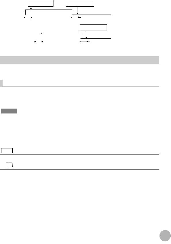
System Configuration
Connecting with EtherCAT |
|
|
(when the master is NX/NJ Series) |
|
|
EtherCAT Master |
Sysmac Studio |
|
|
|
Standard Edition |
I/O control PLC |
|
|
NX/NJ-series Machine |
|
|
Automation Controller |
|
|
Trigger input |
General-purpose USB Cable |
|
General-purpose Ethernet Cable |
|
|
sensor |
|
|
Special EtherCAT |
|
|
Cable (RJ45/RJ45) |
ZW-8000@/7000@/5000@ |
|
24-V |
|
Other EtherCAT slaves |
|
|
|
power supply |
|
|
Power Cable
Parallel Cable
Special EtherCAT Cable |
(RJ45/RJ45) |
Special EtherCAT Cable |
(RJ45/RJ45) |
Connecting with EtherCAT (when the |
EtherCAT Master |
|
master is other than NX/NJ Series) |
||
|
|
Sysmac Studio |
|
|
|
Displacement Sendor |
|
|
|
Edition |
|
|
|
|
Programmable Controller |
|
|
General-purpose |
with CJ2 CPU Unit |
|
|
|
|
|
|
Ethernet Cable |
|
|
|
|
Special EtherCAT |
|
|
|
Cable (RJ45/RJ45) |
|
|
|
|
ZW-8000@/7000@/5000@ |
|
24-V |
|
Other EtherCAT slaves |
I/O control PLC |
|
|
|
power supply |
|
|
|
|
|
|
|
|
Power |
Special EtherCAT Cable |
Special EtherCAT Cable |
|
Cable |
||
Trigger input |
|
(RJ45/RJ45) |
(RJ45/RJ45) |
sensor |
Parallel Cable |
|
|
|
|
||
EtherNet/IP and No-protocol |
|
Control PLC, RC, or MC |
|
|
Ethernet Connections |
|
|
|
|
|
Sysmac Studio |
|
|
|
|
Displacement Sendor |
|
|
|
|
Edition |
|
Programmable Controller |
NX/NJ-series Machine |
|
|
|
||
|
General-purpose |
with CJ2 CPU Unit |
Automation Controller |
|
|
Ethernet Cable |
|
|
|
|
General-purpose |
|
|
|
Industrial |
Ethernet Cable |
General-purpose |
|
|
EtherNet/IP/ |
|
|
Ethernet Cable |
ZW-8000@/7000@/5000@ |
Ethernet |
|
|
|
|
Switching Hub |
|
|
|
|
|
General-purpose |
|
|
|
|
Ethernet Cable |
|
|
|
24-V |
|
|
|
|
power supply |
Power Cable |
|
Parallel Cable |
|
|
|
|
||
|
|
|
|
|
|
Control signal |
I/O control PLC |
|
|
|
input sensor |
|
||
|
|
|
|
|
16 |
Checking the System Configuration |
ZW-8000/7000/5000 |
|
User’s Manual for Communications Settings

Connection Compatibility
Connected to |
Other connection |
|
|
|
|
ZW-8000@/7000@/ |
|
|
|
|
|
5000@ |
EtherCAT |
EtherNet/IP |
Ethernet |
RS-232C |
Parallel I/O Cable |
|
|
(no-protocol) |
(no-protocol) |
|
|
|
|
|
|
||
|
|
|
|
|
|
EtherCAT |
--- |
Not compatible |
Compatible |
Compatible |
Compatible |
|
|
|
|
|
|
EtherNet/IP |
Not compatible |
--- |
Compatible |
Compatible |
Compatible |
|
|
|
|
|
|
Ethernet |
Compatible |
Compatible |
--- |
Compatible |
Compatible |
(no-protocol) |
|
|
|
|
|
|
|
|
|
|
|
RS-232C |
Compatible |
Compatible |
Compatible |
--- |
Compatible |
(no-protocol) |
|
|
|
|
|
|
|
|
|
|
|
Important
•EtherCAT and EtherNet/IP connections cannot be used at the same time.
•Can be connected simultaneously via Ethernet with PC tools (Sysmac Studio, SmartMonitorZW) and another device (PLC etc). Can be connected simultaneously via Ethernet with PC tools (Sysmac Studio, SmartMonitorZW) and another device (PLC etc). The port number for the PC tool is 9600 (fixed) and 9602 (fixed). When connecting different devices, set the port number to other than 9600 and 9602 (default value is 9601).
•When the measurement cycle is 40µs or less and ETherCAT is connected, analog output is not executed.
Product |
Model |
Application |
|
|
|
ZW |
ZW-8000@/7000@/5000@ |
This Displacement Sensor performs measurements. |
|
|
|
PC Tool |
Sysmac Studio Standard |
This is the setup application. It is part of the Sysmac Studio Package and it |
|
Edition |
runs on Windows. |
|
• SYSMAC-SE200D |
The Sysmac Studio comes in two different editions. |
|
• Sysmac Studio Standard Edition |
|
|
(no licenses included |
|
|
The Sysmac Studio provides an integrated development environment for |
|
|
(media only)) |
|
|
the NX/NJ series Controllers and other Machine Automation Controllers |
|
|
• SYSMAC-SE201L |
|
|
and EtherCAT Slaves. It supports setup, programming, debugging, |
|
|
(1-license edition) |
|
|
operation, and maintenance. |
|
|
• SYSMAC-SE2@@L |
|
|
The Sysmac Studio Standard Edition DVD includes Support Software for |
|
|
(multilicense editions |
|
|
EtherNet/IP, DeviceNet, serial communications, and PT screen design |
|
|
(3, 10, 30, or 50 |
|
|
(CX-Designer). Refer to the Sysmac catalog (Cat. No. P072) for details. |
|
|
licenses)) |
|
|
• Sysmac Studio Measurement Sensor Edition |
|
|
Sysmac Studio |
|
|
This license provides the functions that are required to set up ZW-8000/ |
|
|
Measurement Sensor |
|
|
7000/5000 Series Vision Sensors from the Sysmac Studio. This model |
|
|
Edition |
|
|
number is for the license only. You must also purchase the DVD for the |
|
|
• SYSMAC-ME00@L |
|
|
Sysmac Studio Standard Edition Ver.1.22 or higher. |
|
|
(1 or 3 licences) |
|
|
|
|
|
|
|
Special EtherCAT Cable |
* |
The Special EtherCAT Cable connects the Sensor to another Sensor or to |
|
|
another EtherCAT device. |
|
|
|
General-purpose Ethernet |
--- |
Prepare commercially available Ethernet cable |
cable |
|
satisfying the following requirements: |
|
|
• Category 5e or more, 30 m or less |
|
|
• RJ45 connector (8-pin modular jack) |
|
|
• For direct connection: Select cross cable. |
|
|
• For connection through an industrial switching hub: Select straight cable. |
|
|
|
Special RS-232C Cable |
For connecting to a PLC or |
Connect the sensor with a PLC, programmable terminal, or personal |
|
programmable terminal |
computer etc.. |
|
• ZW-XPT2 |
|
|
For connecting to a PC |
|
|
• ZW-XRS2 |
|
|
|
|
Industrial EtherNet/IP / |
• W4S1-03B |
The Switching Hub connects multiple Sensors to one Touch Finder or one |
Ethernet Switching Hub |
(3 ports type) |
computer running PC Tool. |
|
• W4S1-05B |
|
|
• W4S1-05C |
|
|
(5 ports type) |
|
|
|
|
Specifications Communication of Overview 1
|
|
17 |
|
ZW-8000/7000/5000 |
Checking the System Configuration |
||
|
User’s Manual for Communications Settings

Product |
Model |
Application |
|
|
|
EtherCAT Junction Slave |
• GX-JC03 |
Used to connect multiple sensors or PLCs using EtherCAT. |
|
(3 ports type) |
|
|
• GX-JC06 |
|
|
(6 ports type) |
|
|
|
|
*: Refer to Displacement Sensor ZW-8000/7000/5000 series Confocal Fiber Type Displacement Sensor User's Manual (Z362) "9-1 Specifications and External Dimensions".
18 |
Checking the System Configuration |
ZW-8000/7000/5000 |
|
User’s Manual for Communications Settings
Parallel I/O Connection
2-1 Parallel I/O Connection . . . . . . . . . . . . . . . . . . . . . . . . . . . . . . . . . . . . . 20
Connection I/O Parallel 2

2-1 Parallel I/O Connection
I/O Signal Functions
The following describes the functions of I/O signals.

 Analog Output Terminals
Analog output
Name |
Description |
|
|
|
|
Analog voltage output |
This outputs the measured value from -10 V to +10 V as the voltage value. |
|
|
|
When measurement not possible: Approx. 10.8V (default value, can be selected by user) |
|
|
At alarm: Approx. 10.8V |
|
|
|
Analog current output |
This outputs the measured value, from 20 mA to 4 mA as the current value. |
|
|
|
When measurement not possible: Approx. 21 mA (default value, can be selected by user) |
|
|
At alarm: Approx. 21 mA |
|
|
|
|
32-pole expansion connector |
|
|
||
|
|
|
|
|
|
|
|
|
Judgment output |
|
|
|
|
|
Name |
Description |
|
|
|
|
HIGH output |
Judgment result HIGH (HIGH threshold value < measured value) is output. |
|
|
|
|
PASS Output |
Judgment result PASS (LOW threshold value ≤ measured value ≤ HIGH threshold value) is |
|
|
|
output. |
|
|
|
LOW output |
Judgment result LOW (LOW threshold value > measured value) is output. |
|
|
|
|
ALARM output |
|
|
|
|
|
Name |
Description |
|
|
|
|
ALARM output |
This turns ON when there is a system error. |
|
|
|
|
BUSY output |
|
|
|
|
|
Name |
Description |
|
|
|
|
BUSY output |
This turns ON during sampling with the hold function enabled. |
|
|
|
It allows you to check whether or not the self-trigger is functioning correctly. |
|
|
It also turns ON during bank switching. |
|
|
This signal is turned ON in FUNC mode. |
|
|
|
ENABLE output |
|
|
|
|
|
Name |
Description |
|
|
|
|
ENABLE output |
This turns ON when the sensor is ready for measurement. |
|
|
|
This output is interlocked with the ENABLE indicator. |
|
|
|
20 |
Parallel I/O Connection |
ZW-8000/7000/5000 |
|
User’s Manual for Communications Settings

SYNCFLG/TRIGBUSY output
Name |
Description |
|
|
SYNCFLG/TRIGBUSY output |
In the internal/PDO synchronized mode, this output signal operates as SYNCFLG. This turns ON |
|
when measurement synchronization processing is executed by SYNC input and the state |
|
changes to one where normal measurement values can be output. |
|
In the external synchronous measurement mode, this output signal operates as TRIGBUSY. This |
|
turns ON while a measurement by TRIG input is being performed. The next TRIG input cannot |
|
be turned ON until this turns OFF. |
|
|
STABILITY output
Name |
Description |
|
|
STABILITY output |
Turns ON when the 1 surface is in the measuring range. |
|
|
LOGSTAT output
Name |
Description |
|
|
LOGSTAT output |
This turns ON while internal logging is in execution. |
|
|
LOGERR output
Name |
Description |
|
|
LOGERR output |
Turns ON when memory for Internal logging is full and the executes Internal logging. |
|
|
TASKSTAT output
Name |
Description |
|
|
TASKSTAT output |
This turns ON when the measurement value is finalized. |
|
|
ZERO input
Name |
Description |
|
|
ZERO input |
This is used to execute and clear a zero reset. |
|
|
RESET input
Name |
Description |
|
|
RESET input |
This resets all executing measurements and outputs. |
|
While a RESET is being input, judgment output conforms to the non-measurement setting. |
|
If this RESET input switches ON while the hold function is used, the state in effect before the |
|
hold function was set will be restored. |
|
|
TIMING input
Name |
Description |
|
|
TIMING input |
This timing input is for signal input from external devices. Use it for hold function timing. |
|
|
Connection I/O Parallel 2
|
|
21 |
|
ZW-8000/7000/5000 |
Parallel I/O Connection |
||
|
User’s Manual for Communications Settings

LIGHT OFF input
Name |
Description |
|
|
LIGHT OFF input |
Turns OFF the light for measurement. |
|
While LIGHT OFF is being input, the analog output and judgment output conform to the non- |
|
measurement setting. |
|
|
LOGGING input
Name |
Description |
|
|
LOGGING input |
This is used to start internal logging. |
|
|
SYNC/TRIG input
Name |
Description |
|
|
SYNC input |
This is used to synchronize imaging between multiple ZW. With external synchronous |
|
measurement mode selected, this signal works as TRIG input. |
|
For the following conditions, it performs as a SYNC input. |
|
• [Fieldbus] setting: When either [OFF] or [EtherNet/IP] is selected. |
|
• [Synchronous measurement mode] setting: When Internal/PDO synchronized mode is |
|
selected. |
For the following conditions, it performs as a TRIG input.
•[Internal synchronous measurement mode] setting: When select [External synchronous measurement mode].
Important
When the Internal synchronous measurement mode is External synchronous measurement mode, updates each input signals by inputting the TRIG input signal. To be enabled each input signal, enter the TRIG input signal.
Settings for Parallel Input
Used for preventing chattering in parallel input and malfunction due to noise.
Item |
Setting item |
Setting value |
Description |
|
|
|
|
|
|
I/O settings |
Width of input signal |
5 μs/10 μs/20 μs/50 μs/ |
Set the width of filter. |
|
|
filter |
100 |
μs/200 μs/500 μs/ |
|
|
|
1000 μs |
|
|
|
|
100 |
μs (default value) |
|
|
|
|
|
|
Multi View Explore |
: [Bank Group] | [(Bank Data Name)] (double click) |
→ Edit pane |
: [I/O Settings] icon ( ) |
→ I/O Setting Screen |
: [I/O Settings] |
1 Set [Width of input signal filter].
22 |
Parallel I/O Connection |
ZW-8000/7000/5000 |
|
User’s Manual for Communications Settings
Example) When the filter setting value is 100μs (default value)
As an ON state persists for 100μs, an ON or OFF state of TIMING signal is detected. Therefore, a delay in the detection of TIMING signal occurs for a period of time equivalent to the set filter value.
Without chattering |
ON state is detected as ON |
OFF state is detected as OFF |
|
state persists for 100µs. |
state persists for 100µs. |
ON
TIMING |
|
|
|
|
|
|
|
|
|
|
|
|
|
|
|
|
|||||||||
OFF |
|
|
|
|
|
|
|
|
|
|
|
|
|
|
|
|
|
|
|
|
|
|
|
|
|
|
|
|
|
|
|
|
|
|
|
|
|
|
|
|
|
|
|
|
|
|
|||||
|
|
|
|
|
|
100µs |
|
|
|
|
|
|
|
|
|
|
|
|
100µs |
|
|||||
With chattering |
|
|
|
|
|
|
|
|
|
|
|
||||||||||||||
|
|
|
|
|
|
ON state is detected as ON |
|
|
|
|
|
|
|
||||||||||||
|
|
|
|
|
|
|
|
|
|
|
|
|
|
|
|
state persists for 100µs. |
|
|
|||||||
ON |
|
|
|
|
|
|
|
|
|
|
|
|
|
|
|
|
|
|
|
|
|||||
|
|
|
|
|
|
|
|
|
|
|
|
|
|
|
|
|
|
|
|
|
|||||
|
|
|
|
|
|
|
|
|
|
|
|
|
|
|
|
|
|
|
|
|
|||||
TIMING |
|
|
|
|
|
|
|
|
|
|
|
|
|
|
|
|
|
|
|
|
|||||
OFF |
|
|
|
|
|
|
|
|
|
|
|
|
|
|
|
|
|
|
|
|
|
|
|
||
|
|
|
|
|
|
|
|
|
|
|
|
|
|
|
|
|
|
|
|
|
|
|
|
|
|
|
|
|
|
|
|
|
|
|
|
|
|
|
|
|
|
|
|
|
|||||||
|
|
|
|
|
|
|
|
|
|
|
|
|
|
|
100µs |
||||||||||
OFF state is detected as OFF state persists for 100µs.
100µs
Settings for Analog Output
The following describes the settings for outputting the current measurement results from the analog output of the analog output terminal block.
Setting the analog output destination |
With analog output, the measurement results can be output converted to a current from 4 to 20 mA or a voltage from -10 to +10 V.
Selects which to output, the current or the voltage.
Important
The same output destination is set for all banks. The output destination cannot be set separately for individual banks.
Item |
Setting item |
Setting value |
Description |
|
|
|
|
Sensor settings |
Analog output |
Voltage output |
Voltage output |
|
|
(default value) |
|
|
|
|
|
|
|
Current output |
Current output |
|
|
|
|
Note
The analog output destination can also be set with key operations on the Sensor Controller.
Setting the analog output destination p.160
1 Set the operating mode to the FUNC mode.
 Displacement Sensor ZW-8000/7000/5000 series Confocal Fiber Type Displacement Sensor User's Manual (Z362) "3-2 Switching operation modes"
Connection I/O Parallel 2
|
|
23 |
|
ZW-8000/7000/5000 |
Parallel I/O Connection |
||
|
User’s Manual for Communications Settings

Multi View Explore |
: [Device Group] | [(Sensor Name)] | [System] | |
→ Edit pane |
[System Data] (double-click) |
: [Sensor settings] icon ( ) |
2 Select the output destination from [Analog output].
Important
When satisfies the following conditions, the analog output is disabled. A clamp value is output.
•Measurement cycle is 40 µs or less.
•EtherCAT communication is selected in the Fieldbus.
24 |
Parallel I/O Connection |
ZW-8000/7000/5000 |
|
User’s Manual for Communications Settings

 Assigning Analog Output
Set the task for which to output the results as analog.
Item |
Setting item |
Setting value |
Description |
|
|
|
|
Analog output |
Output object |
None/TASK1/TASK2/TASK3/ |
Select the task to output as analog. |
|
|
TASK4 |
|
|
|
|
|
1 Set the operating mode to the FUNC mode.
 Displacement Sensor ZW-8000/7000/5000 series Confocal Fiber Type Displacement Sensor User's Manual (Z362) "3-2 Switching operation modes"
Multi View Explore |
: [Bank Group] | [(Bank Data Name)] (double click) |
→ Edit pane |
: [I/O Settings] icon ( ) |
→ I/O Setting Screen |
: [Analog output] |
2 Select the task from [Output object].
You can select from the above setting values. None/TASK1/TASK2/TASK3/TASK4
Note
Analog output can also be assigned with key operations on the Sensor Controller.
Assigning Analog Output p.161
Connection I/O Parallel 2
|
|
25 |
|
ZW-8000/7000/5000 |
Parallel I/O Connection |
||
|
User’s Manual for Communications Settings
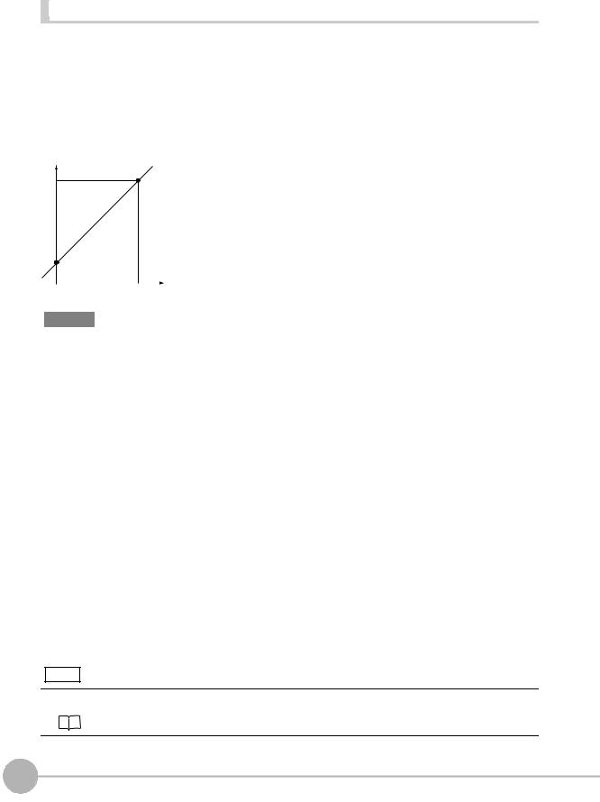
Setting Monitor Focus |
With analog output, the relationship between the output value and measured value to be displayed can be set as desired to convert the measurement result to 4 to 20 mA current or -10 to +10 V voltage before output. Set the focus to match the connected external device.
The output range can be set by entering the output value for the current or voltage values for any two points.
Example: When setting 4 mA output (1st point) for measured value of 0 mm and 20 mA output for measured value of 1 mm (2nd point) (current output)
Output current (mA)
20 |
Point 2 |
|
4 |
|
Point 1 |
|
0 |
|
|
Measured value |
|
1 |
(mm) |
|
0 |
|||
Important
•Separate the two specified points by at least 1% of the rated measuring range of the connected Sensor Head or 40 μm.
•After executing functions that add/subtract the span and offset values to/from the measurement value, execute the monitor focus.
Item |
Setting item |
|
Setting value |
Description |
|
|
|
|
|
|
|
Monitor |
Monitor focus |
|
ON/OFF (default value) |
Sets monitor focus ON/OFF. |
|
focus |
|
|
|
|
|
|
Point1 |
|
Distance |
-999.999999 to 999.999999 [mm] |
Sets the reference measured value for output. |
|
|
|
value |
|
The default setting differs depending on the Sensor |
|
|
|
|
|
Head. |
|
|
|
|
|
|
|
|
|
Current |
4 (default value) to 20 [mA] |
When the analog output destination is set to current, |
|
|
|
output value |
|
sets the current to be output when the distance value is |
|
|
|
|
|
measured. |
|
|
|
|
|
|
|
|
|
Voltage |
-10 (default value) to 10 [V] |
When the analog output destination is set to voltage, |
|
|
|
output value |
|
sets the voltage to be output when the distance value |
|
|
|
|
|
is measured. |
|
|
|
|
|
|
|
Point2 |
|
Distance |
-999.999999 to 999.999999 [mm] |
Sets the reference measured value for output. |
|
|
|
value |
|
The default setting differs depending on the Sensor |
|
|
|
|
|
Head. |
|
|
|
|
|
|
|
|
|
Current |
4 (default value) to 20 [mA] |
When the analog output destination is set to current, |
|
|
|
output value |
|
sets the current to be output when the distance value is |
|
|
|
|
|
measured. |
|
|
|
|
|
|
|
|
|
Voltage |
-10 (default value) to 10 [V] |
When the analog output destination is set to voltage, |
|
|
|
output value |
|
sets the voltage to be output when the distance value |
|
|
|
|
|
is measured. |
|
|
|
|
|
|
Note
The monitor focus can also be set with key operations on the Sensor Controller.
Setting Monitor Focus p.161
26 |
Parallel I/O Connection |
ZW-8000/7000/5000 |
|
User’s Manual for Communications Settings

1 Set the operating mode to the FUNC mode.
 Displacement Sensor ZW-8000/7000/5000 series Confocal Fiber Type Displacement Sensor User's Manual (Z362) "3-2 Switching operation modes"
Multi View Explore |
: [Device Group] | [(Sensor Name)] | [Bank Group] | |
→ Edit pane |
[(Bank Data Name)] (double click) |
: [I/O Settings] icon ( ) |
|
→ I/O Setting Screen |
: [Analog output] |
2 Select ON from [Monitor Focus].
3 Enter the [Distance] and [Output value] at [Point1].
4 Likewise, enter the [Distance] and [Output value] at [Point2].
Adjusting the analog output value |
Discrepancies may occur between the current value/voltage value output as analog set on the Sensor Controller and the current value/voltage value actually measured due to the conditions for the connected external device or other factors.
The analog output adjustment function can be used to correct this discrepancy.
The output values are corrected by entering the adjustment value for the current or voltage values for any two points.
Important
Set the output destination and select either current or voltage output beforehand. Also, connect the analog output signal line to an external ammeter or voltmeter.
Item |
Setting item |
Setting value |
Description |
|
|
|
|
|
|
Analog out- |
Analog output adjustment |
ON/OFF (default value) |
Set analog output correction ON/OFF. |
|
put adjust- |
|
|
|
|
ment |
Point1 |
Reference value |
4 to 20 [mA]/-10 to 10 [V] |
Sets the current or voltage to be used as the correction |
|
|
(current/value) |
|
reference in the entry field on the left. |
|
|
|
|
|
|
|
adjustment value |
-999 to 999 |
Sets the adjustment value when the reference value is |
|
|
|
|
measured in the entry field on the right. |
|
|
|
|
|
|
Point2 |
Reference value |
4 to 20 [mA]/-10 to 10 [V] |
Sets the current or voltage to be used as the correction |
|
|
(current/value) |
|
reference in the entry field on the left. |
|
|
|
|
|
|
|
adjustment value |
-999 to 999 |
Sets the adjustment value when the reference value is |
|
|
|
|
measured in the entry field on the right. |
|
|
|
|
|
Connection I/O Parallel 2
|
|
27 |
|
ZW-8000/7000/5000 |
Parallel I/O Connection |
||
|
User’s Manual for Communications Settings

1 Set the operating mode to the FUNC mode.
 Displacement Sensor ZW-8000/7000/5000 series Confocal Fiber Type Displacement Sensor User's Manual (Z362) "3-2 Switching operation modes"
Multi View Explore |
: [Device Group] | [(Sensor Name)] | [Bank Group] | |
→ Edit pane |
[(Bank Data Name)] (double click) |
: [I/O Settings] icon ( ) |
|
→ I/O Setting Screen |
: [Analog output] |
2 Select ON from [Analog output adjustment].
Important
This setting is allowable only when Online.
3 Click [Setting].
The “Analog Output Adjust” popup menu appears.
4 Enter the [Distance] and [Output value] at [Point1], and click [Output].
5
6
Likewise, enter the [Distance] and [Output value] at [Point2], and click [Output].
Click [Setting].
Note
Analog output values can also be adjusted with key operations on the Sensor Controller.
Adjusting the analog output value p.163
28 |
Parallel I/O Connection |
ZW-8000/7000/5000 |
|
User’s Manual for Communications Settings
Loading...