

Omron Z510 DATASHEET
Welding Bead Sensor
Flatness OK ( 0/ 201) Last
Step
Depth:Bead :
Gap
Flatness
PEAK-BTM
Length
Z510
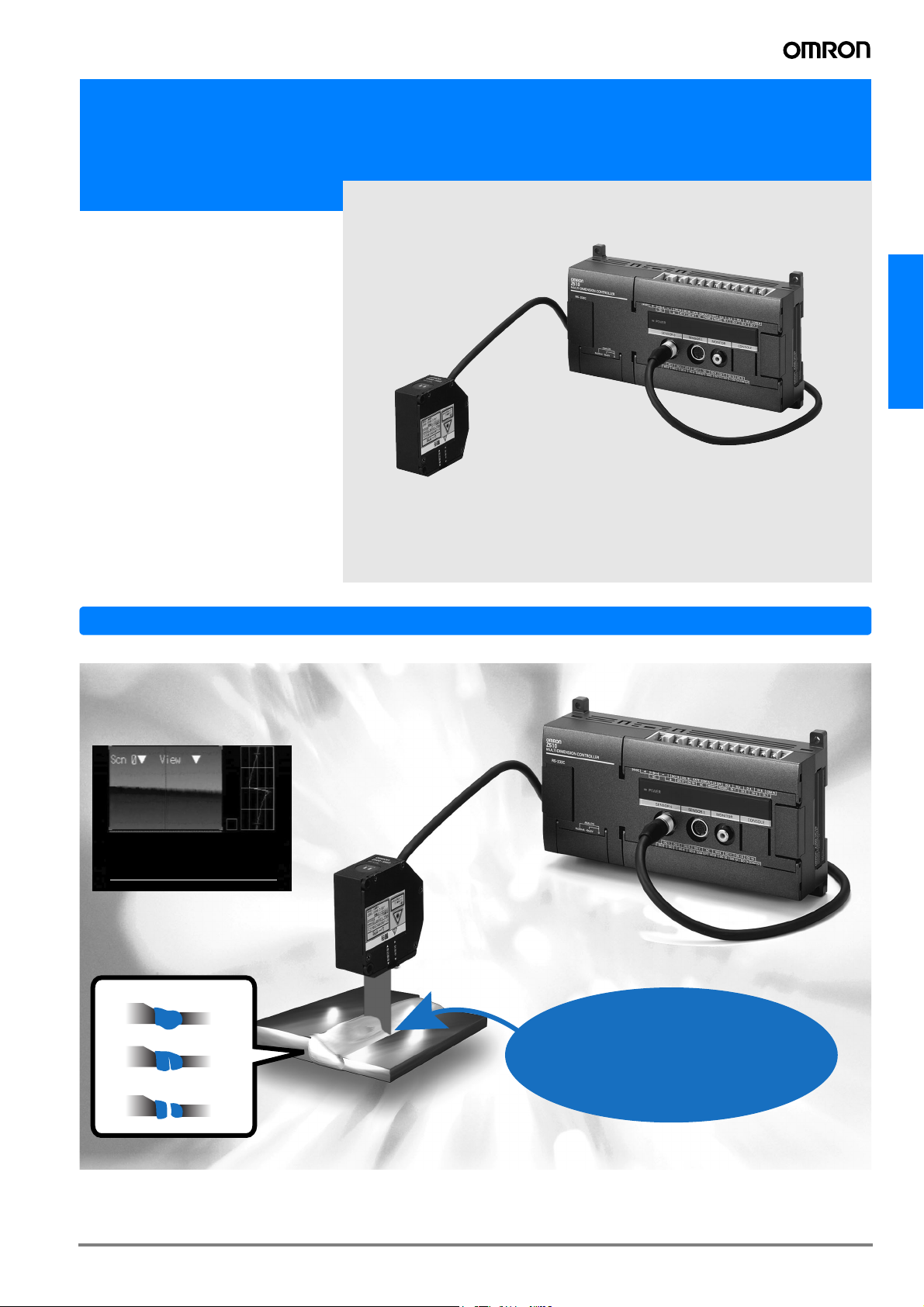
• Inspect for welding flaws by measuring the bead shape.
• Accumulate and output the profile data. Greatly simplify the management
of welding bead quality.
• The high-speed 10-ms measurement
period allows 100% in-line inspection.
• Automatic light intensity (brightness)
adjustment provides stable measurement of fluctuating metal surfaces.
• The compact sensor head contains
both the transmitter and receiver, so
mounting space is not an issue.
In-line Inspection of Welding Beads
Z510
Improve quality by performing 100% inspection of weld strength uniformity.
Display the Inspection Results or 3D Shape Data
Flatness OK ( 0/ 201) Last
Step
:
Depth:Bead :
Gap
Flatness
PEAK-BTM
Length
ESC: Back SFT + ENT/ESC : Save/Load
Detect Various Bead Flaws
Bead shape
Cracks or pinholes
−0000. 51846 mm PASS
−0000. 33351 mm PASS
:
+0000. 24302 mm PASS
:
−0000. 23053 mm PASS
:
+0000. 50820 mm PASS
:
+0000. 25458 mm PASS
Features
Wide laser beam for
fast, highly accurate
inspections
Gaps in the weld
B-53Z510
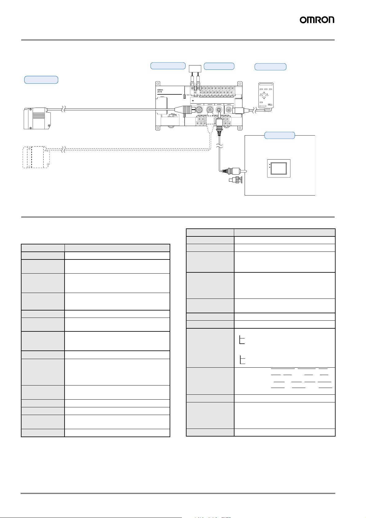
Basic System Configuration
g
Sensors
Z510-SW2T (0.5-m cable)
Z510-SW6 (0.5-m cable)
Z510-SW17 (0.5-m cable)
Sensor Extension Cables
Z519-SCIR (1.5 m, 3 m, 6 m, 8 m, 13 m, or 18 m)
Specify the required cable length when ordering.
Up to 2 Sensors can be connected.
Specifications
Controllers:
Z510-WC10E and Z510-WC15E
General Specifications
Item Specification
Supply voltage 21.6 to 26.4 VDC
Current
consumption
Insulation
resistance
Dielectric
strength
Leakage current 10 mA max.
Noise resistance
Vibration
resistance
Shock resistance
Ambient
temperature
Ambient
humidity
Atmosphere No corrosive gases
Grounding
Degree of
protection
Material Case: ABS
1 A max. (with 2 Sensors connected)
20 MΩ min. (at 100 V DC) between DC exter-
nal terminals and GR terminal
(with internal surge absorber removed)
1,000 VAC, 50/60 Hz between DC external terminals and GR terminal (with internal surge
absorber removed)
1,500 V
P-P; pulse width: 0.1 µs/1 µs; rising
edge: 1-ns pulse
10 to 150 Hz (double amplitude of 0.1 mm)
for 8 minutes each in the X, Y, and Z directions
200 m/s
2
3 times each in 6 directions
Operating: 0 to 50°C (with no icing or condensation)
Storage: -15 to 60°C (with no icing or condensation)
Operating and storage: 35% to 85% (with no
condensation)
Less than 100 Ω
IEC60529 IP20 (In-panel)
Controllers
Z510-WC10E
Z510-WC15E
F150-VM
Monitor Cable (2 m)
Power supply
BNC Jack
(Included with the F150-VM)
Console
Z300-KP
(2-m cable)
ESC TRIG
ENT
SHIFT
CONSOLE
Monitors
F150-M05L
Color Liquid Crystal Monitor
(pin input)
POWER
SYNC
Use the Monitor to check
the image and display
menus when making
Characteristics
Item Specification
Number of Sensors Up to 2 Sensors can be connected.
Number of scenes 16
Light intensity
tracking function
Automatic (The light intensity tracking
range can be specified.)
Fixed (Select one of 31 stages.)
Select one of the following 6 items:
Measurement
items
Deviation from reference surface, Bead
height, Width, Bead change, Peak/Bottom,
Inspection length
Region
specification
A region can be specified in the direction of
the line beam.
Data storage 2,048 points max.
Trigger function Free-run, External 1, External 2, or Auto
• Judgement output
RS-232C output
Terminal block output
Results output
Terminal block
• Measurement value output
(measurement value)
RS-232C output
output
Analo
8 input points: TRIGGER
, LD-OFF, RE-
SET, DI0, and DI4 to DI7
12 output points:DO0 to DO5, DO8, DO15,
to DO19, and GATE
DO17
Monitor interface 1 channel (for pin jack or overscan monitor)
The full-scale output can be divided into
Analog output
resolution
40,000 gradations max.
Resolution (See note.): 0.25 mV (± 5 V)
0.4 µA (4 to 20 mA)
Weight Approx. 700 g (Controller only)
Note: This resolution is for measurements with an OMRON K3AS Linear Sen-
sor Controller connected and values averaged over 64 measurements.
B-54 Displacement sensors / Width-measuring Sensors
 Loading...