

Omron VARISPEED J7 DATASHEET
CIMR-J7AZ
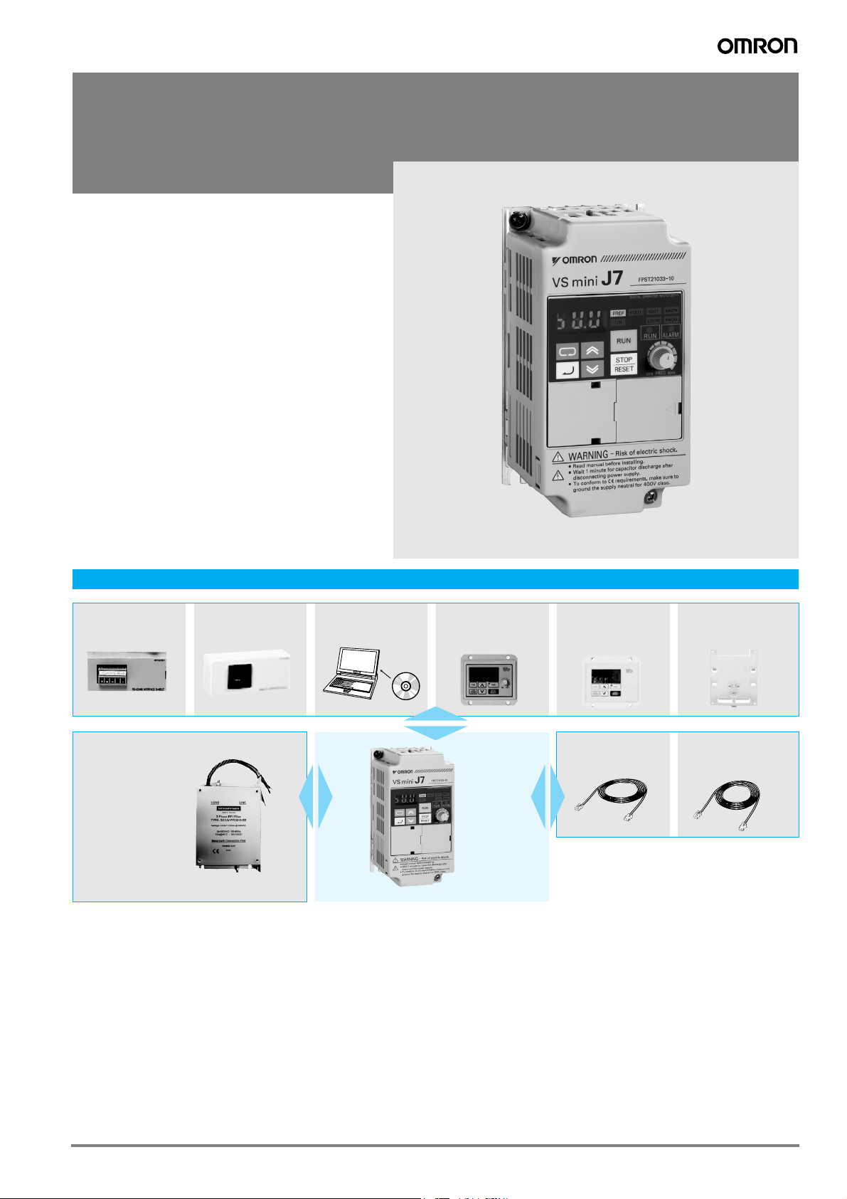
Varispeed J7
Small, simple and smart
• V/f controlled inverter
• Compact size
• Good torque performance: 100% torque at 1.5 Hz,
150% at 3 Hz
• 150% overload / 60sec
• Overload detection function.
• Motor thermal function
• Freely configurable V/f curve
• 4 programmable digital input
• 1 programmable digital output
• 1 programmable analog output
• Optional RS-232C/485 communication - Modbus
• PC Configuration tool: CX-drive
• CE, UL, and cUL marking
Ratings
• 200 V class single-phase 0.1 to 1.5 kW
• 200 V class three-phase 0.1 to 4.0 kW
• 400 V class three-phase 0.2 to 4.0 kW
System configuration
SI-485/J7
Line filter
SI-232/J7
SI-232/J7C
CX-Drive
JVOP-144
Remote digital oper.
with potentiometer
Varispeed
J7
JVOP-146
Remote digital oper.
with potentiometer
3G3IV-PCN329-E
Inverter to PC cable
3G3IV-PEZZ8122_
DIN attachment
3G3IV-PCN126/326
Digital operator
extension cable
351Varispeed J7
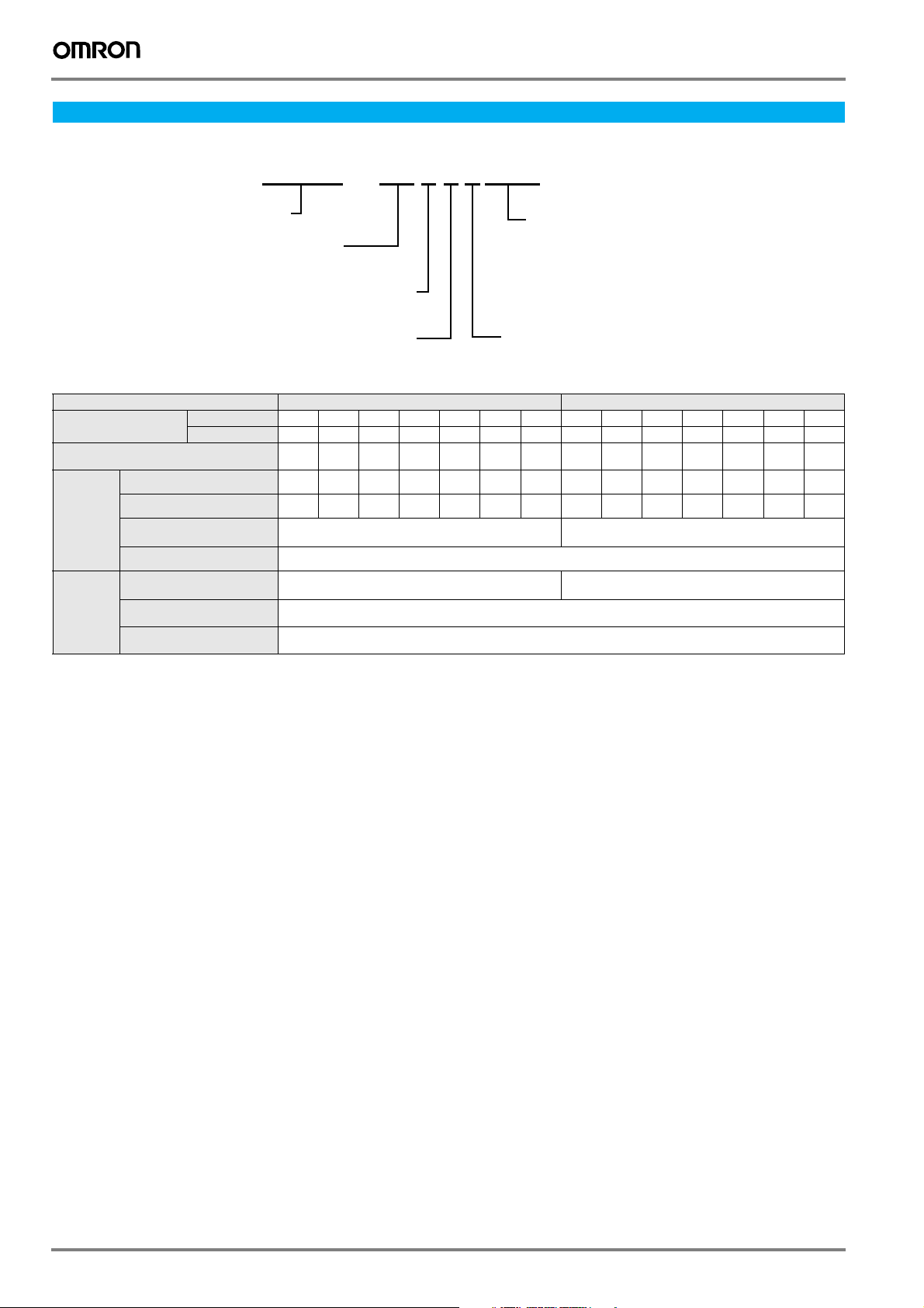
Specifications
Type designation
CIMR—J7AZ20P1
Inverter
J7 series
A: With digital operator (with potentiometer)
Z: European standard
specifications
Voltage class 200 V single/three-phase 400 V three-phase
Model CIMR-J7AZ#
Max. applicable
motor output kW (HP)
Inverter capacity kVA
Rated output current A
Output
characteristics
Power
supply
1. Single-phase series inverter output is three-phase (for three-phase motors)
2. Based on a standard 4-pole motor for max. applicable motor output. Select the inverter model whose rated current is larger than motor rated current.
Max. output voltage V
Max. output frequency
Rated input voltage
Allowable voltage
Allowable frequency
Three-phase 20P1 20P2 20P4 20P7 21P5 22P2 24P0 40P2 40P4 40P7 41P5 42P2 43P0 44P0
Single-phase
and frequency
function
function
1
B0P1B0P2B0P4B0P7B1P5–––––––––
2
0.12 0.25 0.55 1.1 1.5 2.2 4.0 0.37 0.55 1.1 1.5 2.2 3.0 4.0
0.3 0.6 1.1 1.9 3.0 4.2 6.7 0.9 1.4 2.6 3.7 4.2 5.5 7.0
0.8 1.6 3 5 8 11 17.5 1.2 1.8 3.4 4.8 5.5 7.2 9.2
3-phase, 200 to 230 V (proportional to input voltage)
Single-phase, 200 to 240 V (proportional to input voltage)
3-phase, 200 to 230 V, 50/60 Hz
Single-phase, 200 to 240 V, 50/60 Hz
Max. applicable motor output
0P1: 0.1 kW
~
4P0: 4.0 kW
"P" indicates a decimal
[ ]
point
Voltage
B: Single-phase 200 VAC
2: Three-phase 200 VAC
4: Three-phase 400 VAC
3-phase, 380 to 460 V (proportional to input voltage)
400 Hz (programmable)
3-phase, 380 to 460 V, 50/60 Hz
–15 to +10%
±5%
352 Frequency inverters
Commom specifications
Model
CIMR-J7AZ#
Control method
Output frequency range
Frequency tolerance
Resolution of frequency set value
Resolution of output frequency
Overload capability
Frequency set value
Accel/decel time
Control functions
Braking torque
V/f characteristics
Digital inputs Four of the following input signals are selectable: forward/reverse run (3-wire sequence), fault reset, external fault (NO/NC
Digital outputs Following output signals are selectable (NO/NC contact output): Fault, running, zero speed, speed agreed,
Standard functions Full-range automatic torque boost, slip compensation, 9-step speed operation (max.), restart after momentary power loss,
Functionality
Display
Motor overload protection
Instantaneous overcurrent
Overload
Overvoltage
Undervoltage
Momentary power loss
Cooling fin overheat
Protection
Stall prevention level
Cooling fan fault
Ground fault
Power charge indication
Degree of protection
Cooling
Ambient temperature
Ambient humidity
Storage temperature
Installation
Installation height
Ambient conditions
Vibration
1. Shows deceleration torque for uncoupled motor decelerating from 60 Hz with the shortest possible deceleration time.
contact input), multi-step speed operation, jog command, accel/decel time select, external baseblock (NO/NC contact input),
speed search command, UP/DOWN command, accel/decel hold command, LOCAL/REMOTE selection, communication/
control circuit terminal selection, emergency stop fault, emergency stop alarm, self test
frequency detection (output frequency ≤ or ≥ set value), during overtorque detection, minor error, during baseblock,
operation mode, inverter run ready, during fault retry, during undervoltage detection, reverse running, during speed search,
data output through communication
DC injection braking current at stop/start (50% of inverter rated current, 0.5 sec, or less), frequency reference bias/gain, fault
retry, speed search, frequency upper/lower limit setting, overtorque detection, frequency jump, accel/decel time switch, accel/
decel prohibited, S-curve accel/decel, frequency reference with built-in volume, constants copy (option) MEMOBUS communications (option)
0 to 10 VDC (20 kΩ), 4 to 20 mA (250 Ω), 0 to 20 mA (250 Ω), frequency setting volume (selectable)
Short-term average deceleration torque
Digital operator: available to monitor frequency reference, output frequency, output current
ON until the DC bus voltage becomes 50 V or less, RUN lamp stays ON or digital operator LED stays ON.
Self cooling for 200 V 0,1..0,75 kW (single-phase) 0,1..0,4 kW (Three-phase) and for 400 V 0,2..0,75l kW
Cooling fan for 200 V (single-phase), 0.75 kW..4.0 kW (3-phase) and for 400 V 1,5..4.0 kW
Digital reference: 0.01 Hz (less than 100 Hz), 0.1 Hz (100 Hz or more)
0.1 to 999 sex. (accel/decel time are independently programmed)
Status indicator LED: RUN and ALARM provided as standard LED’s
Motor coasts to a stop at approx. 250% of inverter rated current
Motor coasts to a stop after 1 minute at 150% of inverter rated output current
Motor coasts to a stop if DC bus voltage exceed 410 V (double for 400 V class)
Stops when DC bus voltage is approx. 200 V or less (double for 400 V class)
Following items are selectable: Nnot provided (stop if power loss is 15ms or longer),
continuous operation if power loss is approx. 0.5 s or shorter, continuous operation
Individual level stall prevention can be set during acceleration or constant running,
Protected by electronic circuit (operation level is approx. 250% of rated output current)
Digital reference: ±0.01% (–10 to +50 °C),
Analog reference: ±0.5% (25±10 °C)
Analog reference: 1/1000 of max. output frequency
150% rated output current for one minute
0.4/0.75 kW (0,5 HP, 1HP): 100% or more;
2.2 kW (3 HP) or more: 20% or more
Continuous regenerative torque: Approx 20%
Possible to program any V/f pattern
(approx. 160 V or less for single-phase series)
provided/not provided setting available during deceleration.
Detected by electronic circuit (fan lock detection)
(Charge LED is provided for 400 V)
-20 ºC..+60 ºC (short-term temperature during trasnportation)
Indoor (no corrosive gas, dust, etc.)
10 to 20 Hz, 9.8 m/s2 max; 20 to 50 Hz, 2m/s2 max
Specifications
Sine wave PWM (V/f control)
0.1 to 400 Hz
0.01 Hz
1
: 0.1, 0.2 kW (0.13 HP, 0,25 HP): 150% or more;
1.5 kW (2 HP): 50% or more;
Electronic thermal overload relay
Protected by thermister
IP20
-10 ºC to 50 ºC (non-freezing)
90% RH or less (non-condensing)
Max. 1000 m
Varispeed J7 353

Digital operator
Data display
Digital operator
Function display LEDs
Selected function is lit (see the
functions below). Its data is
displayed on data display.
Display selection key
Switch functions among function
display LEDs.
Enter key
Enter data when setting constants.
After selecting constant no. at
PRGM mode, data are displayed.
Increment key
Increase constant no. or data.
Decrement key
Decrease constant no. or data.
Stop/Reset key
Press to stop the motor. If fault
occurs, reset the inverter.
Operation key
Press to run the motor. The RUN
light is ON while running.
Alarm LED
Run LED
Frequency setting volume
Set operational frequency with
volume.
FREF
Frequency reference
setting/monitoring
F/R
Operator RUN command
FWD/REV selection
FOUT
Output frequency
monitoring
IOUT
Output current
monitoring
LO/RE
LOCAL/REMOTE
selection
MNTR
Multi-function
monitoring
PRGM
Constant no./data
354 Frequency inverters
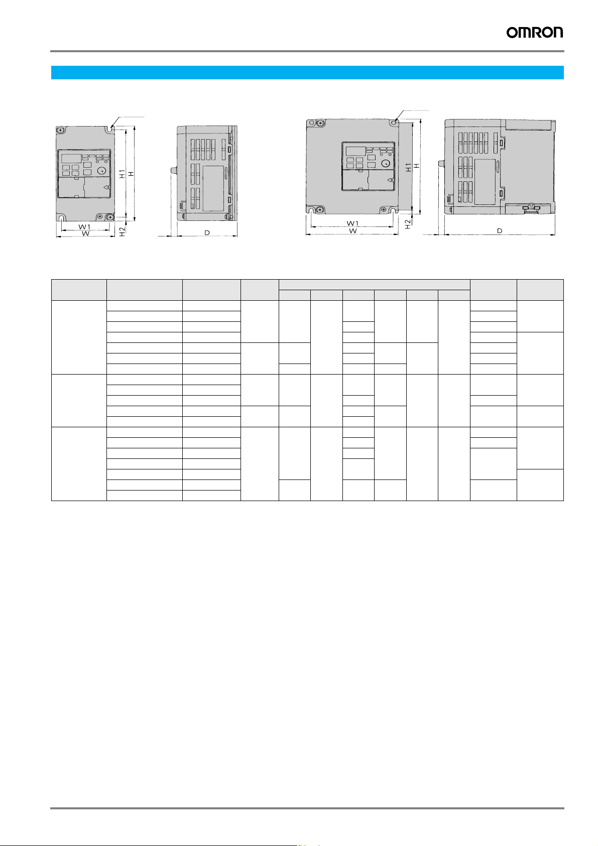
Dimensions
IP 20 type 0.1 to 4 kW
2 – M 4
4 – M 4
Voltage class
200 V
three-phase
200 V
single-phase
400 V
three-phase
8.5
(0.34)
Figure 1 Figure 2
Max. applicable
motor output kW
0.12
0.25
0.55
1.1
1.5
2.2
4.0
0.1
0.2
0.4
0.75
1.5
0.37
0.55
1.1
1.5
2.2
3.0
4.0
Inverter model
CIMR-J7AZ#
20P1
20P2
20P4
20P7
21P5
22P2
24P0
B0P1
B0P2
B0P4
B0P7
B1P5
40P2
40P4
40P7
41P5
42P2
43P0
44P0
Figure
1 68 128 70 56 118 5 0.5 Self cooled
2 108 129 96 118 1.3
1 68 128 70 56 118 5 0.5 Self cooled
2 108 129 96 1.5 Fan cooled
2 108 128 81 96 118 5 1.0 Self cooled
W H D W1 H1 H2
140 161 128 2.1
140 161 128 2.1
Dimensions in mm
102 0.8
122 0.9 Fan cooled
154 1.5
112 0.9
154
99 1.1
129 1.5
154
8.5
(0.34)
Weight kg
7.7
Cooling
method
Fan cooled
Varispeed J7 355
 Loading...