

Page 1
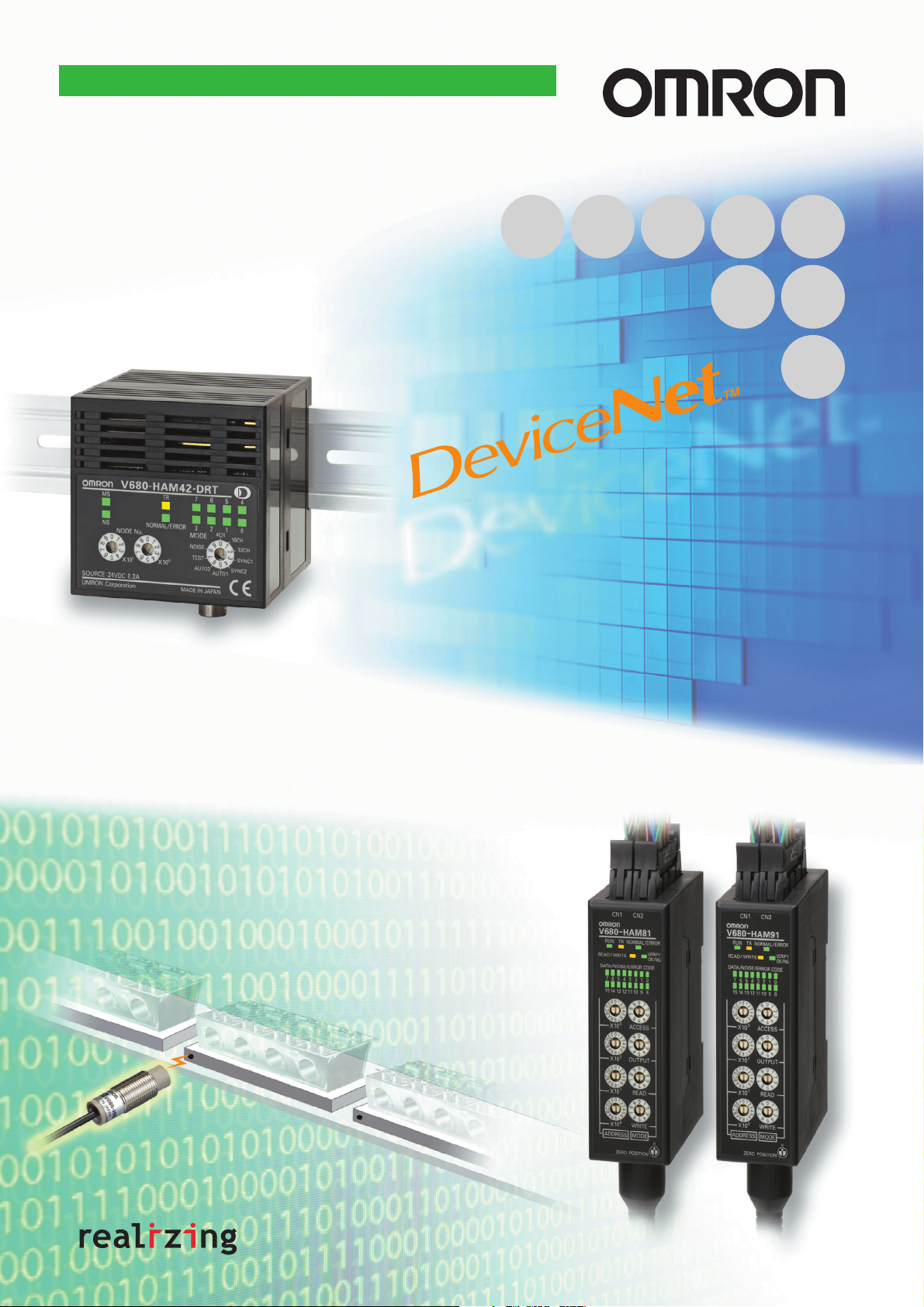
Conforms to International Standards ISO/IEC 18000-3 (ISO/IEC 15693)
V680 RFID
DeviceNet ID Slave
V680-HAM42-DRT
ID Flag Sensors
V680-HAM91/HAM81
RFID with Open Network Compatibility!
V680-HAM42-DRT
Read and write up to 58 bytes.
Use the DeviceNet open network for easier,
more-flexible information management on factory sites.
The RFID System Can Be Used
Just Like a Sensor.
V680-HAM91/HAM81
Read or write 16 bits at a time with one unit.
Useful in applications from simple line sorting or
product identification to managing work progress
or inspection data.
Page 2
V680 DeviceNet ID Slave
V680-HAM42-DRT
V680-series DeviceNet-compatible Slaves
for RFID Systems.
Read and Write Up To 58 Bytes.
• V680-series DeviceNet-compatible Slaves for RFID systems.
• Includes a built-in Amplifier, yet has a compact size of 65 × 65 ×
65 mm. Compatible with V680-series ID Tags and Antennas.
• Read and write 4, 26, or 58 bytes of data.
• Includes an Access Mode compatible with the V600-HAM42-DRT
to enable the use of existing programs.
• Complies with international standards, including CE, UL/CSA,
and radio wave regulations.
Radio wave regulation compliance is applicable to Japan, Europe,
the U.S.A., and Canada. Radio wave regulation compliance for
China and South Korea is pending. Approval for UL/CSA is
pending.
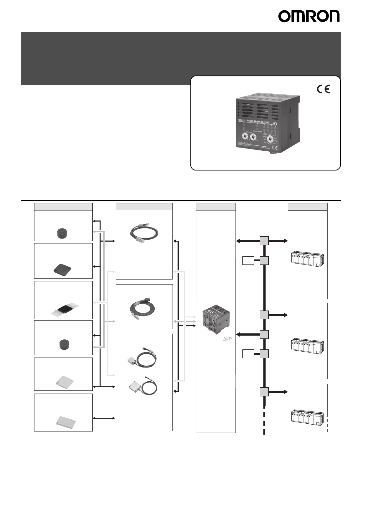
System Configuration
ID Tag Amplifier
1-Kbyte memory
V680-D1KP52MT (8 dia. × 5 mm)
For embedding in metallic or
non-metallic surface
1-Kbyte memory
V680-D1KP66MT/V680-D1KP66T
(34 × 34 × 3.5 mm)
For flush mounting on metallic
surface
1-Kbyte memory
V680-D1KP66T-SP (96 × 36.5 ×
6.5 mm)
For flush mounting on
non-metallic surface
2-Kbyte memory
V680-D2KF52M (8 dia. × 5 mm)
For embedding in metallic or
non-metallic surface
2-Kbyte memory
V680-D2KF67M/V680-D2KF67
(40 × 40 × 4.5 mm)
For flush mounting on non-metallic
surface
Wireless
communications
Read/Write Antenna
Cylinder type
V680-HS52
-W:
Standard cable,
waterproof connector
-R:
Flexible cable,
non-waterproof
connector
Cable length: 2 m or 12.5 m
Cylinder type
V680-HS51
Cable length: 2 m
Square type
V680-HS63
V680-HS65
V680-HAM42-DRT
DeviceNet ID Slave
I/O
I/O
Host
Programmable
Controller
Programmable
Controller
8-Kbyte/32-Kbyte memory
V680-D8KF68/-D32KF68
(86 × 54 × 10 mm)
For flush mounting on
non-metallic surface
-W:
Standard cable,
waterproof connector
Flexible cable,
-R:
non-waterproof
connector
Cable length: 2 m or 12.5 m
Programmable
Controller
Note 1. Attach an Antenna to the V680-HAM42-DRT DeviceNet ID Slave to read and write V680 ID Tag data.
2. The DeviceNet ID Slave can communicate with ID Tags that comply with ISO/IEC 18000-3 (ISO/IEC 15693) in addition to V680-series ID
Tags. Communications with ID Tags other than V680-series ID Tags, however, may not be stable. Always check compatibility completely
before using other ID Tags.
3. Use a V680-HS51/-HS52 Antenna if the V680-D1KP52MT or V680-D2KF52M is to be embedded in metal. Communications cannot be
performed if a V680-HS63 Antenna is used in combination with the V680-D1KP52MT or V680-D2KF52M.
The V680-HS65 Antenna cannot communicate with V680-D1KP52MT or V680-D2KF52M ID Tags if they are embedded in metal.
2 V680-HAM42-DRT, V680-HAM91/-HAM81
Page 3
V680 ID Flag Sensors
V680-HAM91/-HAM81
Easy Setup! The RFID System Can Be Used Just Like
a Sensor.
Read and Write 16 Bits of Data with 1 Unit.
Useful in Applications from Simple Product Identification to Managing Work Progress
• Read or write 16 bits of data (for up to 64,000 IDs) with one Unit
despite its compact size.
• Read or write up to 128 bits by using the address shift function.
• With NPN and PNP outputs
• Equipped with a V600-HAM/HAR-compatible Access Mode, allowing
use of existing programs.
• Complies with international standards, including CE, UL/CSA, and
radio wave regulations.
Radio wave regulation compliance is applicable to Japan, Europe,
the U.S.A., and Canada. Radio wave regulation compliance for China
and South Korea is pending.
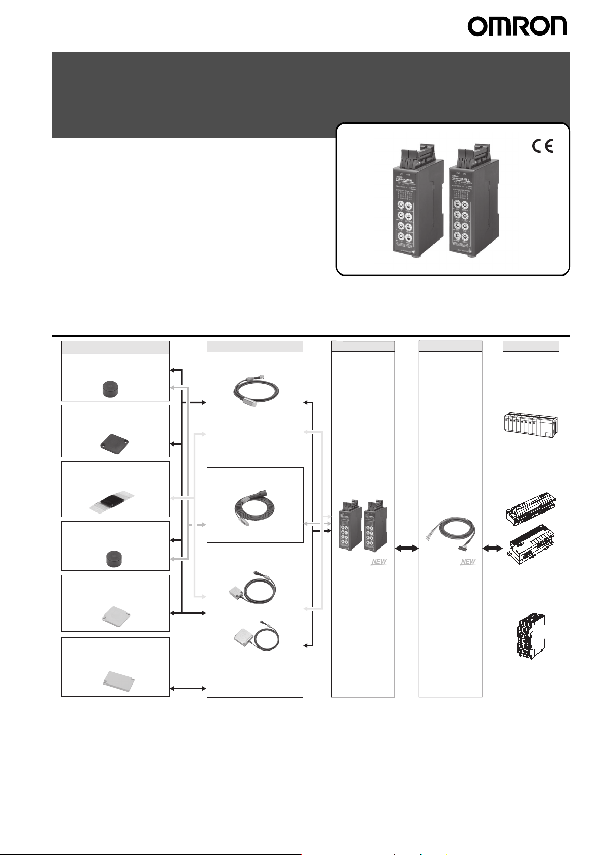
System Configuration
1-Kbyte memory
V680-D1KP52MT (8 dia. × 5 mm)
For embedding in metallic or
non-metallic surface
1-Kbyte memory
V680-D1KP66MT/V680-D1KP66T
(34 × 34 × 3.5 mm)
For flush mounting on metallic surface
1-Kbyte memory
V680-D1KP66T-SP
(96 × 36.5 × 6.5 mm)
For flush mounting on non-metallic
surface
2-Kbyte memory
V680-D2KF52M (8 dia. × 5 mm)
For embedding in metallic or
non-metallic surface
2-Kbyte memory
V680-D2KF67M/V680-D2KF67
(40 × 40 × 4.5 mm)
For flush mounting on non-metallic
surface
ID Tag Amplifier
Read/Write Antenna
Cylinder type
V680-HS52
-W:
Standard cable,
waterproof connector
-R:
Flexible cable,
non-waterproof connector
Cable length: 2 m or 12.5 m
Cylinder type
V680-HS51
Cable length: 2 m
Square type
V680-HS63
V680-HS65
V680-HAM91
(NPN output)
V680-HAM81
(PNP output)
Interface Cable
V680-A60 (2 m)
V680-A60 (5 m)
V680-A60 (10 m)
Connector pins:
26 pins
Host
Programmable
Controller
B7A-series Link
Terminal, I/O
Terminal, etc.
Sensor Controller
8-Kbyte/32-Kbyte memory
V680-D8KF68/-D32KF68
(86 × 54 × 10 mm)
For flush mounting on non-metallic
surface
Note 1. Attach an Antenna to the V680-HAM91/-HAM81 ID Flag Sensor to read and write V680 ID Tag data.
2. The DeviceNet ID Slave can communicate with ID Tags that comply with ISO/IEC 18000-3 (ISO/IEC 15693) in addition to V680-series ID Tags.
Communications with ID Tags other than V680-series ID Tags, however, may not be stable. Always check compatibility completely before using other
ID Tags.
-W:
Standard cable,
waterproof connector
-R:
Flexible cable,
non-waterproof connector
Cable length: 2 m or 12.5 m
3. Use a V680-HS51/-HS52 Antenna if the V680-D1KP52MT or V680-D2KF52M is to be embedded in metal. Communications cannot be
performed if a V680-HS63 Antenna is used in combination with the V680-D1KP52MT or V680-D2KF52M.
The V680-HS65 Antenna cannot communicate with V680-D1KP52MT or V680-D2KF52M ID Tags if they are embedded in metal.
V680-HAM42-DRT, V680-HAM91/-HAM81 3
Page 4
Ordering Information
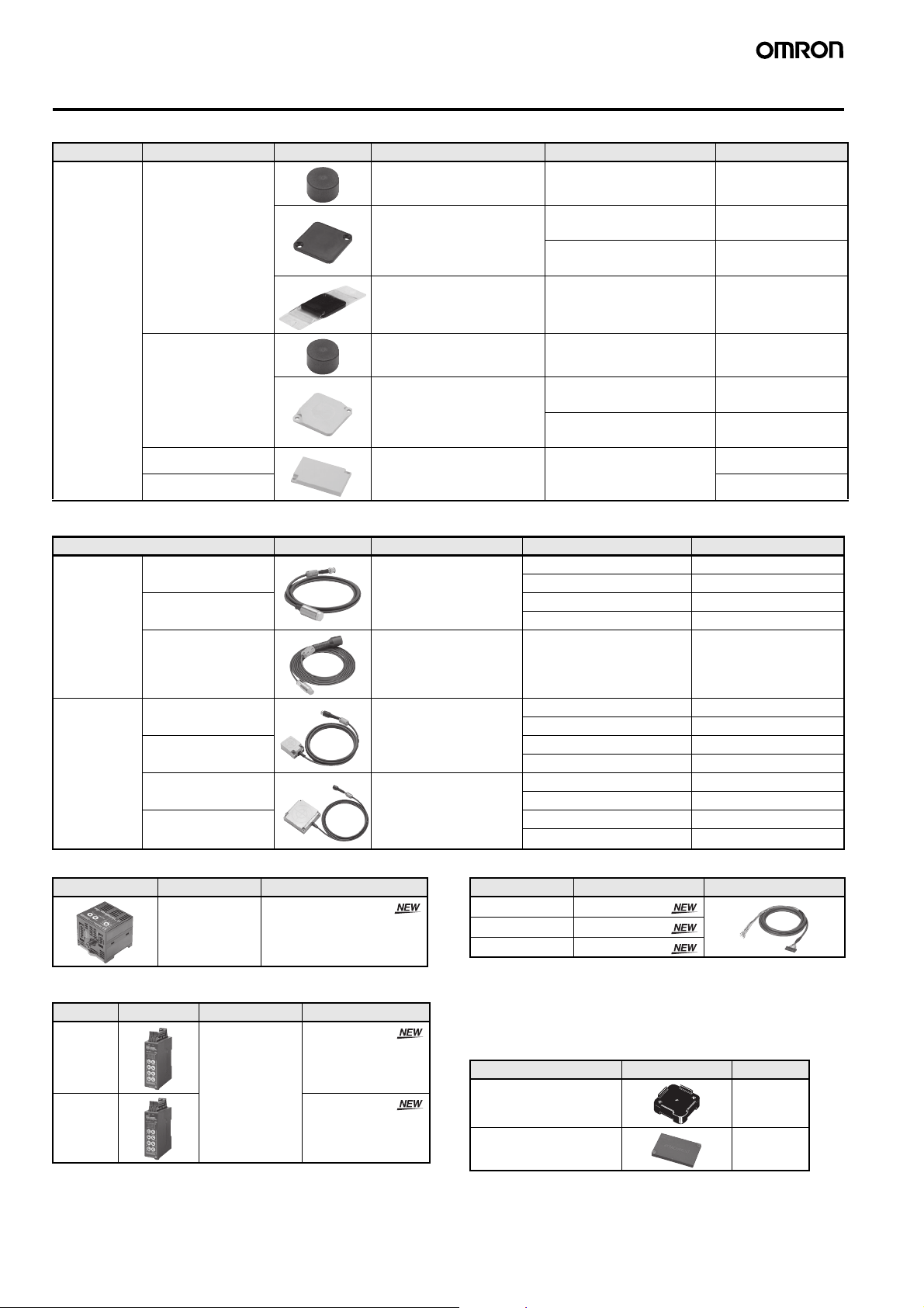
ID Tag
Typ e Memory capacity Appearance Size Metallic compatibility Model
Battery-less 1 Kbyte Cylindrical, ultra-compact
8 dia. × 5 mm
For embedding in metallic or
non-metallic surface
V680-D1KP52MT
Square
34 × 34 × 3.5 mm
Square PFA package
95 × 36.5 × 6.5 mm
2 Kbytes Cylindrical,
8 Kbytes 86 × 54 × 10 mm For flush mounting on non-
32 Kbytes V680-D32KF68
ultra-compact
8 dia. × 5 mm
Square
40 × 40 × 4.5 mm
Read/Write Antenna (Detachable Amplifier Unit Type)
Typ e Appearance Size Cable length Model
Cylindrical Standard cable,
waterproof connector
Flexible cable, nonwaterproof connector
Standard cable, nonwaterproof connector
M22 × 65 mm 2 m V680-HS52-W 2M
M12 × 35 mm 2 m V680-HS51 2M
For flush mounting on metallic
surface
For flush mounting on nonmetallic surface
For flush mounting on nonmetallic surface
For embedding in metallic or
non-metallic surface
For flush mounting on metallic
surface
For flush mounting on nonmetallic surface
metallic surface
12.5 m V680-HS52-W 12.5M
2 m V680-HS52-R 2M
12.5 m V680-HS52-R 12.5M
V680-D1KP66MT
V680-D1KP66T
V680-D1KP66T-SP
V680-D2KF52M
V680-D2KF67M
V680-D2KF67
V680-D8KF68
Square Standard cable,
waterproof connector
Flexible cable, nonwaterproof connector
Standard cable,
waterproof connector
Flexible cable, nonwaterproof connector
Amplifier: ID Slave for DeviceNet
Appearance Size Model
65 × 65 × 65 mm V680-HAM42-DRT
Amplifier: ID Flag Sensor
Typ e Appearance Size Model
NPN output
PNP output
90 × 30 × 65 mm V680-HAM91
V680-HAM81
40 × 53 × 23 mm 2 m V680-HS63-W 2M
12.5 m V680-HS63-W 12.5M
2 m V680-HS63-R 2M
12.5 m V680-HS63-R 12.5M
100 × 100 × 30 mm 2 m V680-HS65-W 2M
12.5 m V680-HS65-W 12.5M
2 m V680-HS65-R 2M
12.5 m V680-HS65-R 12.5M
Interface Cable (for V680-HAM91/81)
Cable length Model Appearance
2 m V680-A60 2M
5 m V680-A60 5M
10 m V680-A60 10M
Note 1. The connectors are not water resistant.
2. The cables can be extended to a maximum length of 10 m.
3. Normally two Interface Cables are required for 1 Unit. If you do not
need to write to ID Tags, or use the address shift or noise check
functions, then one Interface Cable is sufficient.
Accessories (Order Separately)
ID Tag Attachment
Typ e Appearance Model
For the V680-D1KP66T V600-A86
For the V680-D@KF68 V680-A81
4 V680-HAM42-DRT, V680-HAM91/-HAM81
Page 5
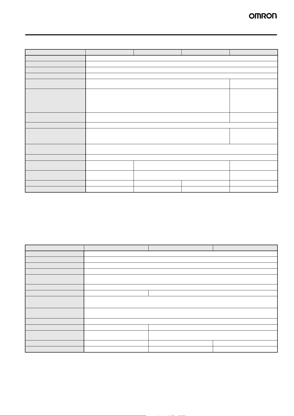
Ratings and Performance
ID Tag (1-Kbyte Memory)
Item Model V680-D1KP52MT V680-D1KP66T V680-D1KP66MT V680-D1KP66T-SP
Memory capacity 1,000 byte (user area)
Memory type EEPROM
Data backup time (See note 1.) 10 years after writing (85°C max.)
Memory longevity 100,000 times per block (at 25°C)
Ambient operating temperature
(during transmission)
Ambient operating temperature
(not during transmission)
Ambient storage temperature −40 to 125°C (with no icing) −40 to 110°C (with no
Ambient operating humidity 35 to 95%
Degree of protection IEC 60529, IP68
Vibration resistance
Shock resistance
Appearance 8 dia. × 5 mm 34 × 34 × 3.5 mm 95 × 36.5 × 6.5 mm
Materials Case: PPS resin
Weight Approx. 0.5 g Approx. 6 g Approx. 7.5 g Approx. 20 g
Metallic compatibility Yes No Yes No
Note 1. Refer to the User's Manual (Cat. No. Z278 or Z279) for data backup time for temperatures of 85°C or higher. If the V680 has been stored
at 125°C or higher, write the data again even if the data does not need to be changed.
2. 150°C heat resistance: The heat resistance has been checked at 150°C for up to 1,000 hours, and thermal shock has been checked
through testing 1,000 thermal cycles each of 30 minutes at −10/150°C. (Test samples: 22, defects: 0)
3. 180°C heat resistance: The heat resistance has been checked at 180°C for up to 200 hours, and thermal shock has been checked through
testing 200 thermal cycles each of 30 minutes at −10°C/180°C. (Test samples: 22, defects: 0)
4. This OMRON in-house standard confirms resistance to cutting and other oils. It is equivalent to the former JEM standard.
5. For details, refer to the User's Manual (Cat. No. Z278 or Z279).
−25 to 85°C (with no icing) −25 to 70°C (with no icing)
−40 to 125°C (with no icing)
Heat resistance: 1,000 thermal cycles each of 30 minutes at −10°C/150°C, High-
In-house standard for antenna oil resistance (former JEM standard equivalent to
IP67g) (See note 4.)
10 to 2,000 Hz, 1.5-mm double amplitude at 150 m/s
15 minutes each
2
500 m/s
Filling: Epoxy resin
temperature storage: 1,000 hours at 150°C (See note 2.)
200 thermal cycles each of 30 minutes at −10°C/180°C, High-
temperature storage: 200 hours at 180°C (See note 3.)
2
acceleration with 10 sweeps in X, Y, and Z directions for
in X, Y, and Z directions 3 times each (18 times in total)
Molding: PPS resin External resin: PFA
−40 to 110°C (with no
icing)
icing)
IP67
(excluding protrusions)
Tag body: PPS resin
ID Tag (2-Kbyte Memory)
Item Model V680-D2KF52M V680-D2KF67 V680-D1KF67M
Memory capacity 2,000 bytes (user area)
Memory type FRAM
Data backup time (See note 1.) 10 years after writing (55°C or less)
Memory longevity 10 billion times per block. Access frequency (See note 2.): 10 billion times
Ambient operating
temperature
Ambient storage temperature −40 to 85°C (with no icing)
Ambient operating humidity 35 to 95% 35 to 85%
Degree of protection IEC 60529, IP67
Vibration resistance
Shock resistance
Appearance 8 dia. × 5 mm 40 × 40 × 4.5 mm
Materials Case: PPS resin
Weight Approx. 0.5 g Approx. 6.5 g Approx. 7 g
Metallic compatibility Yes No Yes
Note 1. Refer to the User's Manual (Cat. No. Z278 or Z279) for data backup time for temperatures of 55°C or higher.
2. The total Read or Write communication frequency is called the access frequency.
3. This OMRON in-house standard confirms resistance to cutting and other oils. It is equivalent to the former JEM standard.
4. For details, refer to the User’s Manual (Cat. No. Z278 or Z279).
−25 to 85°C (with no icing)
In-house standard for antenna oil resistance (former JEM standard equivalent to IP67g) (See note 3.)
10 to 2,000 Hz, 1.5-mm double amplitude at 150 m/s
15 minutes each
2
500 m/s
Filling: Epoxy resin
in X, Y, and Z directions 3 times each (18 times in total)
Molding: ABS resin
Filling: Epoxy resin
2
acceleration with 10 sweeps in X, Y, and Z directions for
V680-HAM42-DRT, V680-HAM91/-HAM81 5
Page 6

ID Tag with 8-/32-Kbyte Memory
Item Model V680-D8KF68 V680-D32KF68
Memory capacity 8,192 bytes (user area) 32,744 bytes (user area)
Memory type FRAM
Data backup time
(See note 1.)
Memory longevity 10 billion times per block at 85°C max. Access frequency (See note): 10 billion times
Ambient operating
temperature
Ambient storage
temperature
Ambient operating
humidity
Degree of protection IEC 60529, IP67
Vibration resistance 10 to 500 Hz, 1.5-mm double amplitude at 100 m/s2 acceleration with 10 sweeps in X, Y, and Z directions for
Shock resistance
Dimensions 86 × 54 × 10 mm
Materials Case: PBT resin
Weight Approx. 50 g
Metallic compatibility No
Note 1. Refer to the User’s Manual (Cat. No. Z278 or Z279) for data backup time for temperatures of 70°C or higher.
2. The total Read or Write communication frequency is called the access frequency.
3. This OMRON in-house standard confirms resistance to cutting and other oils. It is equivalent to the former JEM standard.
4. For details, refer to the User’s Manual (Cat. No. Z278 or Z279).
10 years (at 70°C max.) after data is written
−20 to 85°C (with no icing)
−40 to 85°C (with no icing)
35 to 85%
In-house standard for antenna oil resistance (former JEM standard equivalent to IP67g) (See note 2.)
11 minutes each
2
500 m/s
in X, Y, and Z directions 3 times each (18 times in total)
Filling: Epoxy resin
Cylindrical Read/Write Antenna (Detachable Amplifier Unit Type)
Model
Item
Ambient operating temperature −10 to 60°C (with no icing)
Ambient storage temperature −25 to 75°C (with no icing)
Ambient operating humidity 35% to 95% (with no condensation)
Insulation resistance 20 MΩ min. (at 500 VDC) between the cable terminals and the case
Dielectric strength 1,000 VAC (50/60 Hz) for 1 minute between the cable terminals and the case with a current leakage of 5 mA max.
Degree of protection IP67 (IEC60529)
Vibration resistance
Shock resistance
Appearance M22 × 65 mm M12 × 35 mm
Materials ABS, brass, epoxy resin filling
Weight Approx. 850 g (with 12.5-m cable) Approx. 55 g (with 2-m cable)
Note 1. The degree of protection for the Connector is IP67/IP65. This OMRON in-house standard confirms resistance to cutting and other oils.
It is equivalent to the former JEM standard.
2. The Connector is not waterproof. This OMRON in-house standard confirms resistance to cutting and other oils. It is equivalent to the former
JEM standard.
In-house standard for antenna oil
resistance (former JEM standard
equivalent to IP67g) (Read/Write
Antenna portion) (See note 1.)
10 to 500 Hz variable vibration, 1.5-mm double amplitude at 100 m/s2
acceleration, with 10 sweeps in X, Y, and Z directions for 8 minutes each
500 m/s2 in X, Y, and Z directions 3 times each (18 times in total) 1,000 m/s2 in X, Y, and Z directions
3. For details, refer to the User’s Manual (Cat. No. Z278 or Z279).
V680-HS52-W
(Standard Cable, Waterproof
Connector)
(Flexible Cable, Non-waterproof
IP67 (IEC60529)
In-house standard for antenna oil resistance (former JEM standard equivalent
to IP67g) (Read/Write Antenna portion) (See note 2.)
V680-HS52-R
Connector)
(Standard Cable, Non-waterproof
10 to 2,000 Hz variable vibration,
1.5-mm double amplitude at 150 m/s2
acceleration, with 10 sweeps in X, Y,
and Z directions for 15 minutes each
3 times each (18 times in total)
V680-HS51
Connector)
6 V680-HAM42-DRT, V680-HAM91/-HAM81
Page 7
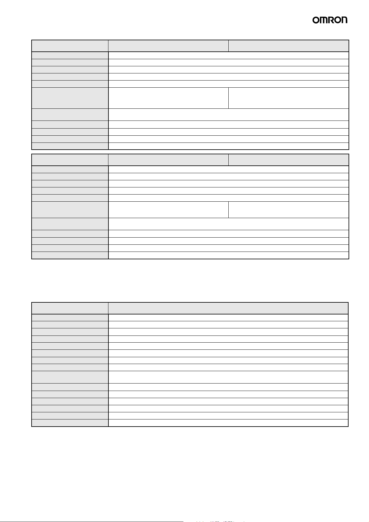
Square Read/Write Antenna (Detachable Amplifier Unit Type)
Item
Ambient operating temperature −10 to 60°C (with no icing)
Ambient storage temperature −25 to 75°C (with no icing)
Ambient operating humidity 35% to 95% (with no condensation)
Insulation resistance 20 MΩ min. (at 500 VDC) between the cable terminals and the case
Dielectric strength 1,000 VAC (50/60 Hz) for 1 minute between the cable terminals and the case with a current leakage of 5 mA max.
Degree of protection IP67 (IEC60529)
Vibration resistance
Shock resistance
Appearance 40 × 53 × 23 mm
Materials ABS, epoxy resin filling
Weight Approx. 850 g (with 12.5-m cable)
Model
(Standard Cable, Waterproof Connector)
In-house standard for antenna oil resistance (former JEM
standard equivalent to IP67g) (Read/Write Antenna
portion) (See note 1.)
10 to 500 Hz variable vibration, 1.5-mm double amplitude at 100 m/s2 acceleration, with 10 sweeps in X, Y, and Z
directions for 11 minutes each
500 m/s2 in X, Y, and Z directions 3 times each (18 times in total)
V680-HS63-W
(Flexible Cable, Non-waterproof Connector)
IP67 (IEC60529)
In-house standard for antenna oil resistance (former JEM
standard equivalent to IP67g) (Read/Write Antenna
portion) (See note 2.)
V680-HS63-R
Item
Ambient operating temperature −25 to 70°C (with no icing)
Ambient storage temperature −40 to 85°C (with no icing)
Ambient operating humidity 35% to 95% (with no condensation)
Insulation resistance 20 MΩ min. (at 500 VDC) between the cable terminals and the case
Dielectric strength 1,000 VAC (50/60 Hz) for 1 minute between the cable terminals and the case with a current leakage of 5 mA max.
Degree of protection In-house standard for antenna oil resistance (former JEM
Vibration resistance
Shock resistance
Appearance 100 × 100 × 30 mm
Materials ABS, epoxy resin filling
Weight Approx. 1,100 g (with 12.5-m cable)
Model
(Standard Cable, Waterproof Connector)
standard equivalent to IP67g) (Read/Write Antenna
portion) (See note 1.)
10 to 500 Hz variable vibration, 1.5-mm double amplitude at 100 m/s2 acceleration, with 10 sweeps in X, Y, and Z
directions for 11 minutes each
500 m/s2 in X, Y, and Z directions 3 times each (18 times in total)
V680-HS65-W
(Flexible Cable, Non-waterproof Connector)
In-house standard for antenna oil resistance (former JEM
standard equivalent to IP67g) (Read/Write Antenna
portion) (See note 2.)
V680-HS65-R
Note 1. The degree of protection for the Connector is IP67/IP65. This OMRON in-house standard confirms resistance to cutting and other oils.
It is equivalent to the former JEM standard.
2. The Connector is not waterproof. This OMRON in-house standard confirms resistance to cutting and other oils. It is equivalent to the former
JEM standard.
3. For details, refer to the User’s Manual (Cat. No. Z278 or Z279).
Amplifier (DeviceNet ID Slave)
Item
Connectable Antennas One channel (V680-HS@@)
Rated voltage 24 VDC (−15% to 10%) including 10% ripple (p-p)
Power consumption 4 W max. (Current consumption of 200 mA max. at power supply voltage of 24 VDC)
Ambient operating temperature −10 to 55°C (with no icing)
Ambient storage temperature −25 to 65°C (with no icing)
Ambient operating humidity 25% to 85% (with no condensation; ambient operating temperature is 40°C max. at humidity of 85%)
Insulation resistance 20 MΩ min. (at 500 VDC) between all terminals excluding the ground terminal and the case
Dielectric strength 1,000 VAC (50/60 Hz) for 1 minute between all terminals excluding the ground terminal and the case
Vibration resistance
Shock resistance
Appearance 65 × 65 × 65 mm (excluding protrusions)
Degree of protection IEC 60529, IP20
Materials Polycarbonate (PC) resin, ABS resin
Weight Approx. 150 g
Mounting DIN Track
Model
10 to 150 Hz, 0.2-mm double amplitude at 15 m/s2 acceleration with 10 sweeps in X, Y and Z directions for 8 minutes
each
150 m/s2 in X, Y, and Z directions 3 times each (18 times in total)
Note 1. For details, refer to the User's Manual (Cat. No. Z278).
2. The number of words allocated in the master depends on the Access Mode. Refer to page 9 for information on Part Names and Operating
Modes.
V680-HAM42-DRT
V680-HAM42-DRT, V680-HAM91/-HAM81 7
Page 8
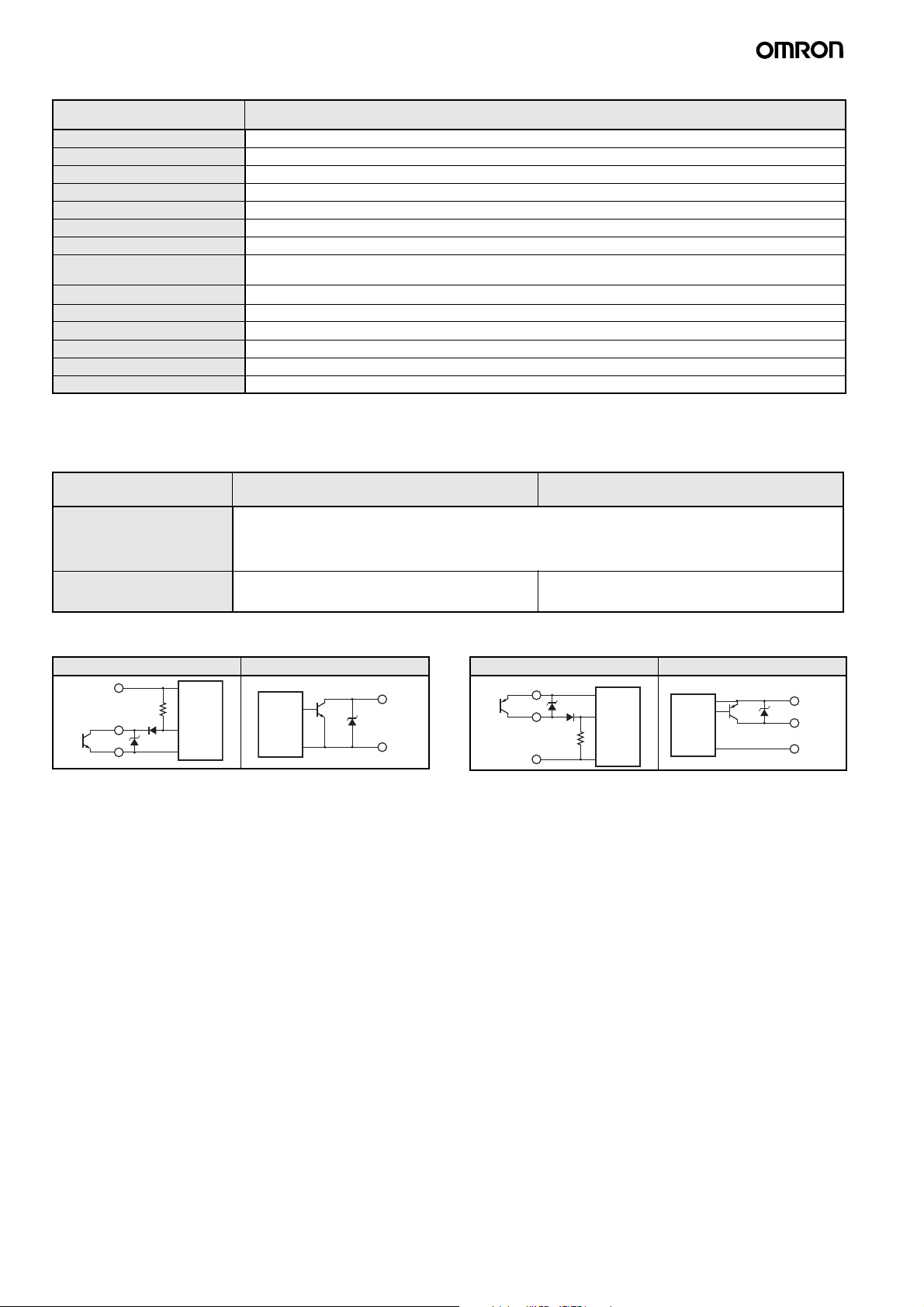
Amplifier: ID Flag Sensor
Item
Model
Rated voltage 24 VDC (−15% to +10%) including 10% ripple (p-p)
Power consumption 3.5 W (24 VDC, 150 mA max. except external I/O line current)
Ambient operating temperature −10 to 55°C (with no icing)
Ambient storage temperature −25 to 65°C (with no icing)
Ambient operating humidity 25% to 85% (with no condensation; ambient operating temperature is 40°C max. at humidity of 85%)
Insulation resistance 20 MΩ min. (at 500 VDC) between all terminals excluding the FG terminal and the case
Dielectric strength 1,000 VAC (50/60 Hz) applied for 1 minute between all terminals excluding the FG terminal and the case
Vibration resistance
Shock resistance
10 to 150 Hz, 0.2-mm double amplitude at 15 m/s2 acceleration with 10 sweeps in X, Y and Z directions for 8 minutes
each
150 m/s2 in X, Y, and Z directions 3 times each (18 times in total)
Appearance 90 × 30 × 65 mm (excluding protrusions)
Degree of protection IEC 60529, IP40
Materials Polycarbonate (PC) resin, ABS resin
Weight Approx. 130 g
Mounting DIN Track
Note 1. For details, refer to the User's Manual (Cat. No. Z278).
2. The connectors are not water resistant. If there is a possibility that water will be splashed onto the ID Sensor Unit, mount it inside of a
control box. Also, be sure to use the V680 as a set with the V680-A60 Interface Cable (sold separately).
V680-HAM91/V680-HAM81
I/O Specifications
Model
Item
Input specifications Transistor output
Output specifications NPN open-collector output
Short-circuit current: 3 mA (TYP) (input terminal and 0-V terminal shorted)
OFF voltage: 15 to 30 VDC, ON voltage: 0 to 5 VDC
Input impedance: 8.2 kΩ
Applied voltage: 30 VDC max.
30 VDC, 20 mA max
Residual voltage: 2 V max.
V680-HAM91 V680-HAM81
PNP open-collector output
30 VDC, 20 mA max
Residual voltage: 2 V max.
I/O Circuit Diagrams
V680-HAM91 V680-HAM81
Input circuit Output circuit
24 VDC
8.2 kΩ
IN
Tr
0 V
Main
circuit
Main
circuit
OUT
0 V
Input circuit Output circuit
24 VDC
Tr
IN
0 V
8.2 kΩ
Main
circuit
Main
circuit
24 VDC
OUT
0 V
8 V680-HAM42-DRT, V680-HAM91/-HAM81
Page 9
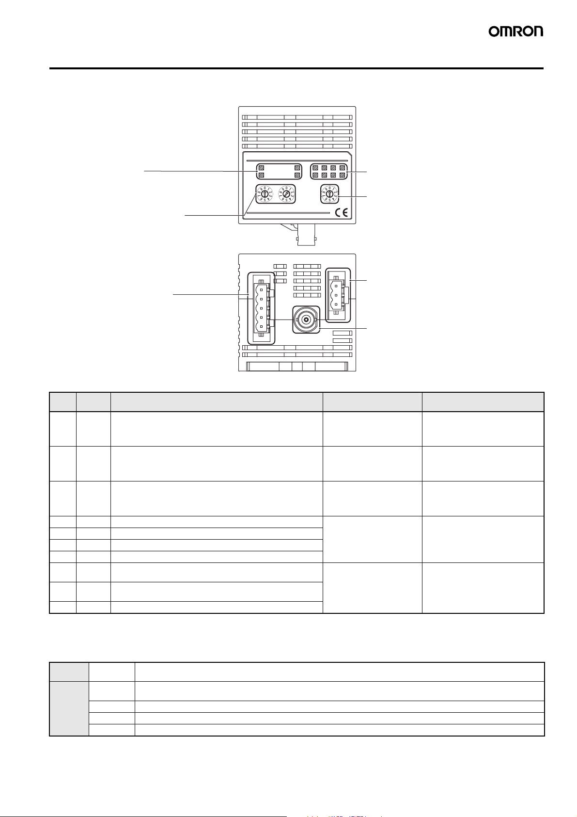
Part Names and Operating Modes
V680-HAM42-DRT
Part Names
OMRON
V680-HAM42-DRT
Operation indicators
MS: ID Slave status
NS: Network status
TR: ID Tag communications status
NORMAL/ERROR: Result of communications with ID Tag
Node Address Switches
Node address switches (setting range: 00 to 63)
DeviceNet Connector
Connects to DeviceNet Master Unit.
Enclosed connector model:
FKC2.5/5-ST-5.08-RFAUM (Phoenix Contact)
MS
NS
SOURCE : 24VDC 0.2A
OMRON Corporation
T/R
NORMAL/ERROR73625140
NODE No. MODE
X101X10
NOISE
0
OFF
FSM RFID
MADE IN JAPAN
TEST
AUTO2
4CH
AUTO1
16CH
SYNC2
32CH
SYNC1
Data/Error Code Indicators (Two-color LED)
Data (green)
Error code (red)
Mode Switch
Sets the operating mode of the ID Slave.
(Refer to the following table.)
Power Supply Terminals
Connect to 24-VDC power.
Recommended Power Supply: S8VS-03024
(Manufactured by OMRON)
Enclosed connector model:
FKC2.5/3-ST-5.08-RF (Phoenix Contact)
Antenna Connector
Connects to a V680-series Antenna (V680-HS@)
Operating Modes
Mode Symbol Description Maximum number of
0 4CH 4-byte Access Mode Read: 4 bytes
1 16CH 26-byte Access Mode Read: 26 bytes
2 32CH 58-byte Access Mode Read: 58 bytes
3 SYNC1 V600-compatible Trigger Mode, 100-ms output time Read: 3 bytes
4 SYNC2 V600-compatible Trigger Mode, 500-ms output time
bytes accessible in ID Tag
Write: 4 bytes
Write: 26 bytes
Write: 58 bytes
Write: 2 bytes
5 AUTO1 V600-compatible Auto Mode, 100-ms output time
6 AUTO2 V600-compatible Auto Mode, 500-ms output time
7 TEST ID Tag Communications Test Mode (Checks standalone op-
eration of ID Slave.)
--- ---
8 NOISE Noise Measurement Mode (Measures the noise around the
Antenna.)
9 --- Setting prohibited
Note 1. The V600-compatible Trigger and Auto Modes can be used with the same I/O settings and control methods that are used with the V600-
HAM42-DRT.
2. Communications with the host device will be offline while the Communications Test Mode or Noise Measurement Mode is being used.
Words allocated in Master Unit
IN: 4 words
OUT: 4 words
(PLC inputs: 64 points,
PLC outputs: 64 points)
IN: 16 words
OUT: 16 words
(PLC inputs: 256 points,
PLC outputs: 256 points)
IN: 32 words
OUT: 32 words
(PLC inputs: 512 points,
PLC outputs: 512 points)
IN: 2 words
OUT: 2 words
Commands (4-byte, 26-byte, 58-byte Access Mode)
Reading READ Data in the ID Tag memory is read by specifying the memory address and the number of bytes to process.
Writing WRITE Data is written to the ID Tag by specifying the memory address, number of bytes to process, and the data.
BIT SET Previously specified bits (i.e., bits that are turned ON) are turned ON in the ID Tag address specified for BIT SET.
BIT CLEAR Previously specified bits (i.e., bits that are turned ON) are turned OFF in the ID Tag address specified for BIT CLEAR.
DATA FILL The specified continuous memory addresses in the ID Tag are filled with the same data.
(The number of bytes can be specified using the Access Mode.)
(The number of bytes can be specified using the Access Mode.)
V680-HAM42-DRT, V680-HAM91/-HAM81 9
Page 10
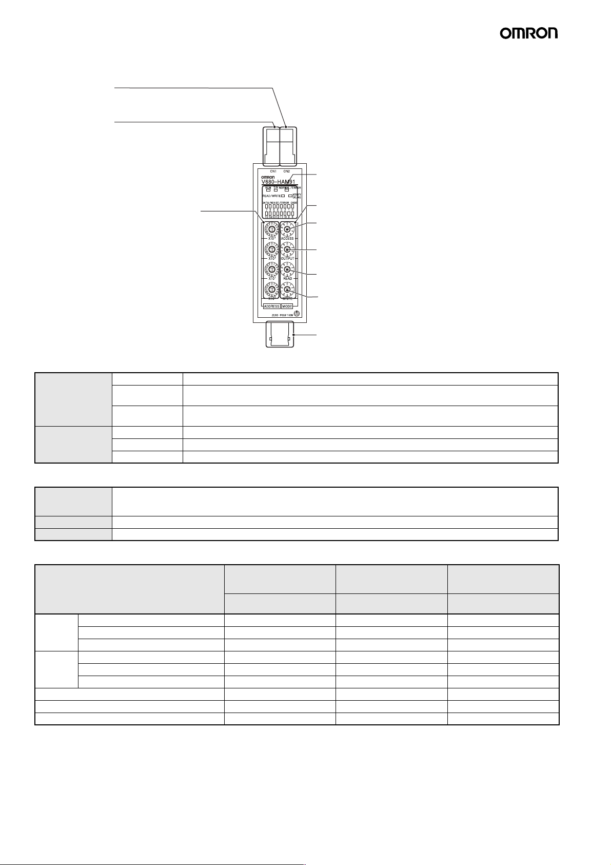
V680-HAM91/-HAM81
Parts Names
I/O connector CN2
Connects to a PLC or other host using an Interface Cable (V680-A60).
This connector is not required if data will not be written to ID Tags or the address
shift function and noise check function will not be used.
I/O connector CN1
Connects to a PLC or other host using an Interface Cable (V680-A60).
Indicators
Indicates the ID Flag Sensor status and ID Tag communications status.
Access Address Mode Setting Switch
Sets the memory address in the ID Tag that
will be accessed.
Mode Setting Switches
Access Mode Setting
Sets the operating mode (SYNC or AUTO) for communications with the ID Tag,
and sets the Noise Measurement Mode. (Refer to the following table.)
Output Mode Setting
Sets the Output Mode (10-ms, 50-ms, or 500-ms OFF-delay), and output
time setting (10-ms, 50-ms, 500-ms, or Continuous output).
Read Mode Setting
Sets the mode for reading from an ID Tag DATA READ, VERIFY,
or Wire-saving Mode.
Write Mode Setting
Sets the mode used when writing
(16-bit write/8-bit write, BIT SET/BIT CLEAR).
Antenna Connector
Connects to a V680-series Antenna (V680-HS@).
Main Functions
Reading Data Read Reads 16 bits of data from the set address in the ID Tag and outputs the data to the data output lines.
Verify Compares the code set in advance with the code read from the ID Tag and outputs the match/mismatch
result.
Wire-saving Mode The wire-saving mode enables reading and writing 16-bit data using one 16-point Input Unit for a PLC
or other host device.
Writing Data Write Writes the data specified in the data input lines. (The user can select to batch-write 16 bits or 8 bits.)
Bit Set Sets specified bits.
Bit Clear Clears specifies bits.
Other Functions
Address Shift When reading or writing more than 16 bits (2 bytes), an address shift can be specified to enable reading or writing up to
Noise Check Measures the noise around the Antenna.
Write Protection Prevents data stored in the ID Tag from being overwritten.
128 bits (16 addresses). The address shift can be set from the host, eliminating the need to change the address set on the
front panel.
Operating Modes
Mode Standard modes V600-HAR91/81 and
Function
AUTO MODE 1
TRIGGER MODE 1
HAM91/81-compatible
modes
AUTO MODE 2
TRIGGER MODE 2
Reading 16 bits ● (●) (See note 1.) ●
Verification Check ●●
Wire-saving Mode (See note 2.) ●●
Writing 8 bits (1 byte) ●●
16 bits (2 bytes) ●●
Individual bits (BIT SET or BIT CLEAR) ●●
Parity check output (See note 3.) ●●
Noise check function ●
Address shift function ●
Note 1. If an error occurs, the error code will not be output to the data output lines (OD0 to OD15).
2. If an error occurs, the data output lines will all turn ON.
3. The parity is also output when the error code is output.
4. The V600-compatible modes are for compatibility with the previous V600 Series. Not all functions are supported in these modes.
V600-HAR92-compatible
modes
AUTO MODE 3
TRIGGER MODE 3
10 V680-HAM42-DRT, V680-HAM91/-HAM81
Page 11
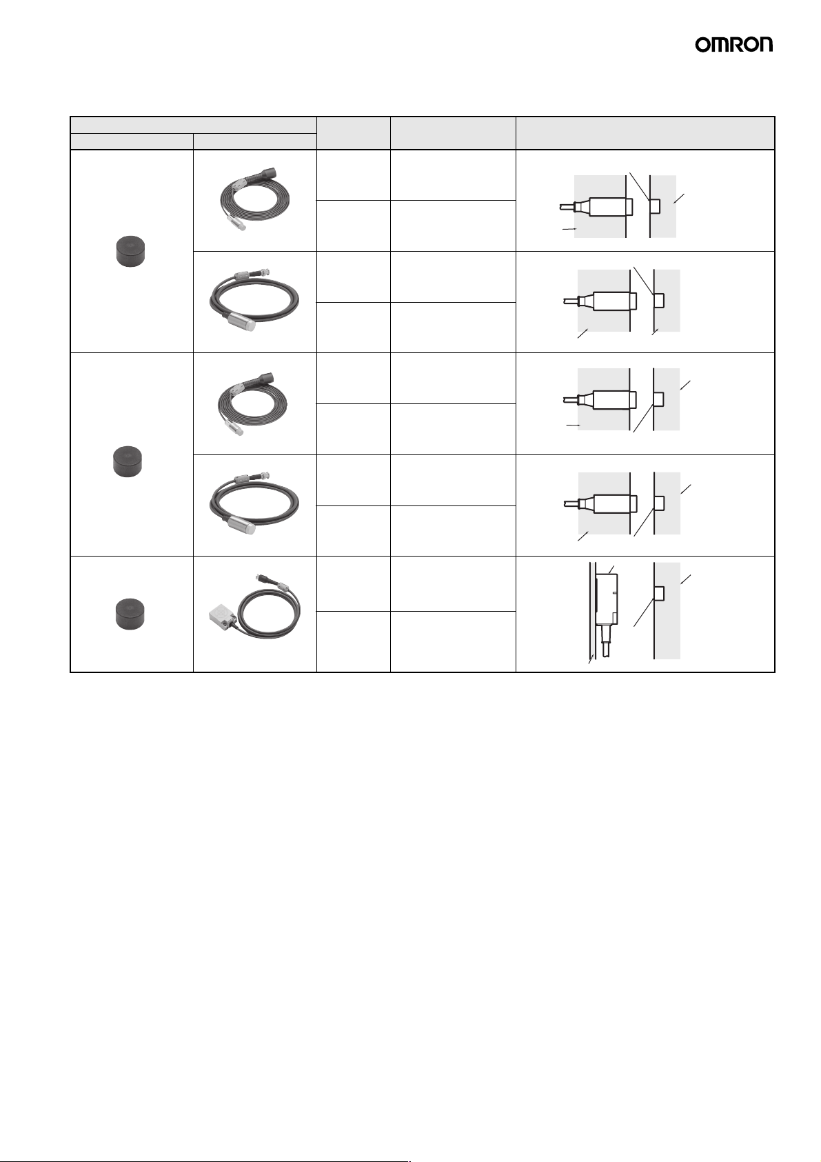
■ Performance Specifications
ID Tag (1-kbyte Memory) Transmission
Recommended combination Function Transmission distance
ID Tag Read/Write Antenna
V680-D1KP52MT V680-HS51 Read
distance
Write
distance
(unit: mm)
0.5 to 6.5 mm
(axial deviation ±2)
0.5 to 6.0 mm
(axial deviation ±2)
ID Tag and Read/Write Antenna mounting
Metallic
conditions
V680-D1KP52MT
V680HS51
Non-metallic
(Resin, plastic, wood, etc.)
V680-D1KP52MT
(embedded in metallic
V680-HS52 Read
V680-HS51 Read
distance
Write
distance
distance
surface: steel)
Write
distance
V680-HS52 Read
distance
Write
distance
V680-D1KP52MT V680-HS63 Read
distance
Write
distance
0.5 to 9.0 mm
(axial deviation ±2)
0.5 to 8.5 mm
(axial deviation ±2)
0.5 to 3.5 mm
(axial deviation ±2)
0.5 to 3.0 mm
(axial deviation ±2)
0.5 to 4.5 mm
(axial deviation ±2)
0.5 to 4.0 mm
(axial deviation ±2)
0.5 to 12.0 mm
(axial deviation ±2)
0.5 to 9.5 mm
(axial deviation ±2)
Metallic
Non-metallic
Non-metallic
V680-D1KP52MT
V680-HS52
V680-
HS51
V680-HS52
V680-HS63
V680D1KP52MT
Non-metallic
(Resin, plastic, wood, etc.)
V680-D1KP52MT
V680-D1KP52MT
Metallic
Metallic
Non-metallic
(Resin, plastic, wood, etc.)
Non-metallic
Note 1. When mounting the V680-HS65, be sure to attach the Mounting Brackets at the base of the Antenna.
The enclosed Mounting Brackets do not need to be used, however, if the mounting brackets on the Antenna are metal plates and their
dimensions are larger than the dimensions of the Antenna (100 × 100 mm).
For details, refer to the User's Manual (Cat. No. Z248 or Z262).
2. The transmission distance may be reduced if the V680-D1KP66T or V680-D1KP58HT is mounted onto a metallic surface. Refer to the
User's Manual (V680-D1KP@@: Cat. No. Z262, V680-D1KP58HT: Cat. No. Z221) for details.
V680-HAM42-DRT, V680-HAM91/-HAM81 11
Page 12
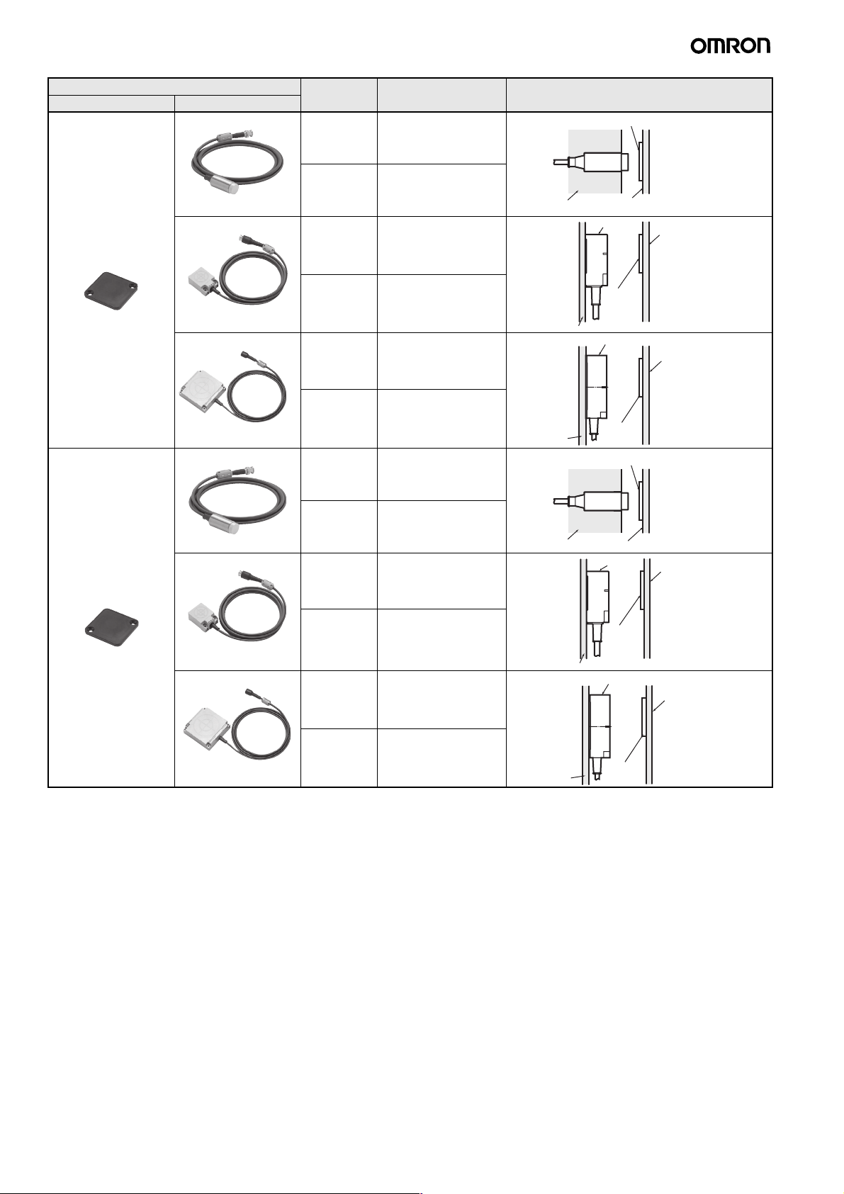
Recommended combination Function Transmission distance
ID Tag Read/Write Antenna
V680-D1KP66T V680-HS52 Read
distance
Write
distance
V680-HS63 Read
distance
(unit: mm)
1.0 to 17.0 mm
(axial deviation ±2)
(See note 2.)
1.0 to 17.0 mm
(axial deviation ±2)
(See note 2.)
5.0 to 30.0 mm
(axial deviation ±10)
(See note 2.)
ID Tag and Read/Write Antenna mounting
conditions
V680-D1KP66T
V680-HS52
Non-metallic
Non-metallic
(Resin, plastic, wood, etc.)
V680-HS63
Non-metallic
(Resin, plastic, wood, etc.)
V680-D1KP66MT
(flush-mounted on
metallic surface: steel)
Write
distance
V680-HS65 Read
distance
Write
distance
V680-HS52 Read
distance
Write
distance
V680-HS63 Read
distance
Write
distance
V680-HS65 Read
distance
5.0 to 25.0 mm
(axial deviation ±10)
(See note 2.)
5.0 to 47.0 mm
(axial deviation ±10)
(See note 2.)
5.0 to 42.0 mm
(axial deviation ±10)
(See note 2.)
1.0 to 16.0 mm
(axial deviation ±2)
1.0 to 14.0 mm
(axial deviation ±2)
5.0 to 25.0 mm
(axial deviation ±10)
5.0 to 20.0 mm
(axial deviation ±10)
5.0 to 25.0 mm
(axial deviation ±10)
Metallic
Non-metallic
Non-metallic
Non-metallic
V680D1KP66T
V680-HS65
V680-HS52
V680-HS63
V680D1KP66MT
V680-HS65
V680D1KP66T
V680-D1KP66MT
Metallic
Non-metallic
(Resin, plastic, wood, etc.)
Metallic
Metallic
Write
distance
5.0 to 20.0 mm
(axial deviation ±10)
12 V680-HAM42-DRT, V680-HAM91/-HAM81
Metallic
V680D1KP66MT
Page 13
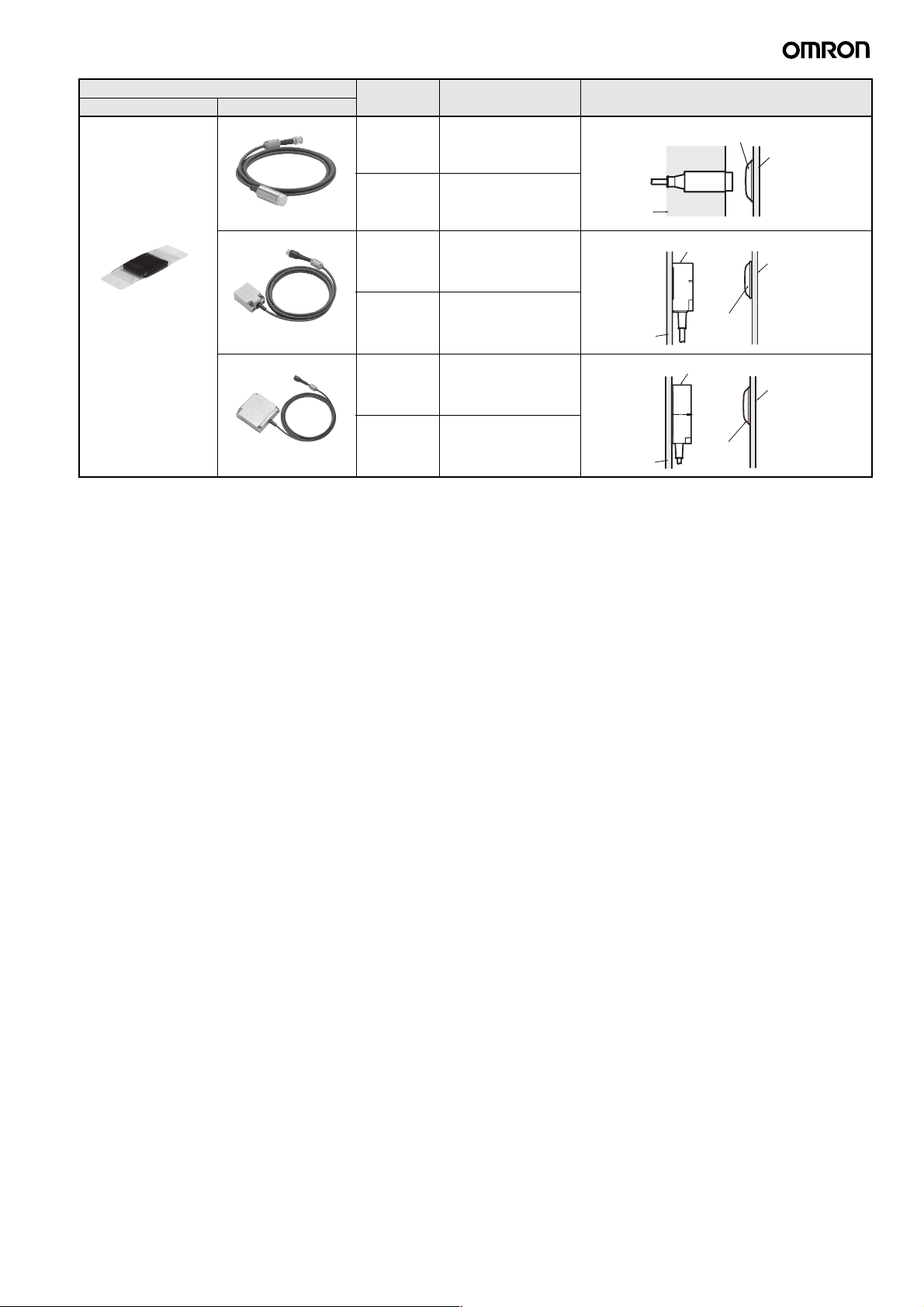
Recommended combination Function Transmission distance
ID Tag Read/Write Antenna
V680-D1KP66T-SP V680-HS52 Read
distance
Write
distance
(unit: mm)
1.0 to 15.0 mm
(axial deviation ±2)
1.0 to 15.0 mm
(axial deviation ±2)
ID Tag and Read/Write Antenna mounting
Non-metallic
conditions
V680-D1KP66T-SP
V680HS52
Non-metallic
(Resin, plastic, wood, etc.)
V680-HS63 Read
distance
Write
distance
V680-HS65 Read
distance
Write
distance
5.0 to 25.0 mm
(axial deviation ±10)
5.0 to 20.0 mm
(axial deviation ±10)
5.0 to 42.0 mm
(axial deviation ±10)
5.0 to 37.0 mm
(axial deviation ±10)
Non-metallic
Metallic
V680-HS63
V680-
D1KP66T-SP
V680-HS65
V680-
D1KP66T-SP
Note 1. When mounting the V680-HS65, be sure to attach the Mounting Brackets at the base of the Antenna.
The enclosed Mounting Brackets do not need to be used, however, if the mounting brackets on the Antenna are metal plates and their
dimensions are larger than the dimensions of the Antenna (100 × 100 mm).
For details, refer to the User's Manual (Cat. No. Z248 or Z262).
2. Refer to the User's Manual (V680-D1KP@@: Cat. No. Z262, V680-D1KP58HT: Cat. No. Z221) for details.
Non-metallic
(Resin, plastic, wood, etc.)
Non-metallic
(Resin, plastic, wood, etc.)
V680-HAM42-DRT, V680-HAM91/-HAM81 13
Page 14
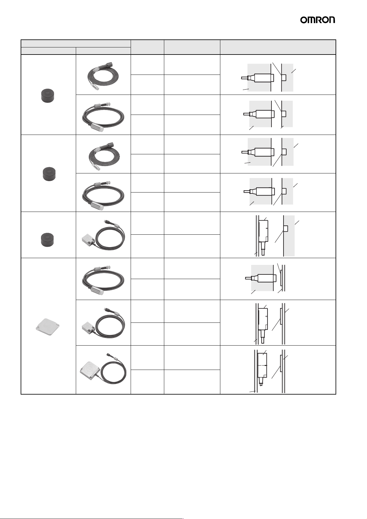
ID Tag (2-kbyte Memory) Transmission
Recommended combination Function Transmission distance
ID Tag Read/Write Antenna
V680-D2KF52M V680-HS51 Read
V680-HS52 Read
V680-D2KF52M
(embedded in metallic
V680-HS51 Read
surface: steel)
V680-HS52 Read
V680-D2KF52M V680-HS63 Read
distance
Write
distance
distance
Write
distance
distance
Write
distance
distance
Write
distance
distance
(unit: mm)
0.5 to 5.5 mm
(axial deviation ±2)
0.5 to 5.5 mm
(axial deviation ±2)
0.5 to 8.0 mm
(axial deviation ±2)
0.5 to 8.0 mm
(axial deviation ±2)
0.5 to 3.5 mm
(axial deviation ±2)
0.5 to 3.5 mm
(axial deviation ±2)
0.5 to 3.0 mm
(axial deviation ±2)
0.5 to 3.0 mm
(axial deviation ±2)
0.5 to 9.5 mm
(axial deviation ±2)
ID Tag and Read/Write Antenna mounting
Metallic
Non-metallic
Metallic
Non-metallic
conditions
V680-D2KF52M
V680-
HS51
V680-D2KF52M
V680-HS52
V680HS51
V680-HS52
V680-HS63
V680-D2KF52M
V680-D2KF52M
Non-metallic
(Resin, plastic, wood, etc.)
Non-metallic
(Resin, plastic, wood, etc.)
Metallic
Metallic
Non-metallic
(Resin, plastic, wood, etc.)
Write
distance
V680-D2KF67 V680-HS52 Read
V680-HS63 Read
V680-HS65 Read
distance
Write
distance
distance
Write
distance
distance
Write
distance
0.5 to 9.5 mm
(axial deviation ±2)
1.0 to 17.0 mm
(axial deviation ±2)
(See note.)
1.0 to 17.0 mm
(axial deviation ±2)
(See note.)
7.0 to 30.0 mm
(axial deviation ±10)
(See note.)
7.0 to 30.0 mm
(axial deviation ±10)
(See note.)
5.0 to 42.0 mm
(axial deviation ±10)
(See note.)
5.0 to 42.0 mm
(axial deviation ±10)
(See note.)
Non-metallic
Non-metallic
Non-metallic
Metallic
V680D2KF52M
V680-D2KF67
V680-HS52
Non-metallic
(Resin, plastic, wood, etc.)
V680-HS63
V680D2KF67
V680-HS65
V680D2KF67
Non-metallic
(Resin, plastic, wood, etc.)
Non-metallic
(Resin, plastic, wood, etc.)
14 V680-HAM42-DRT, V680-HAM91/-HAM81
Page 15
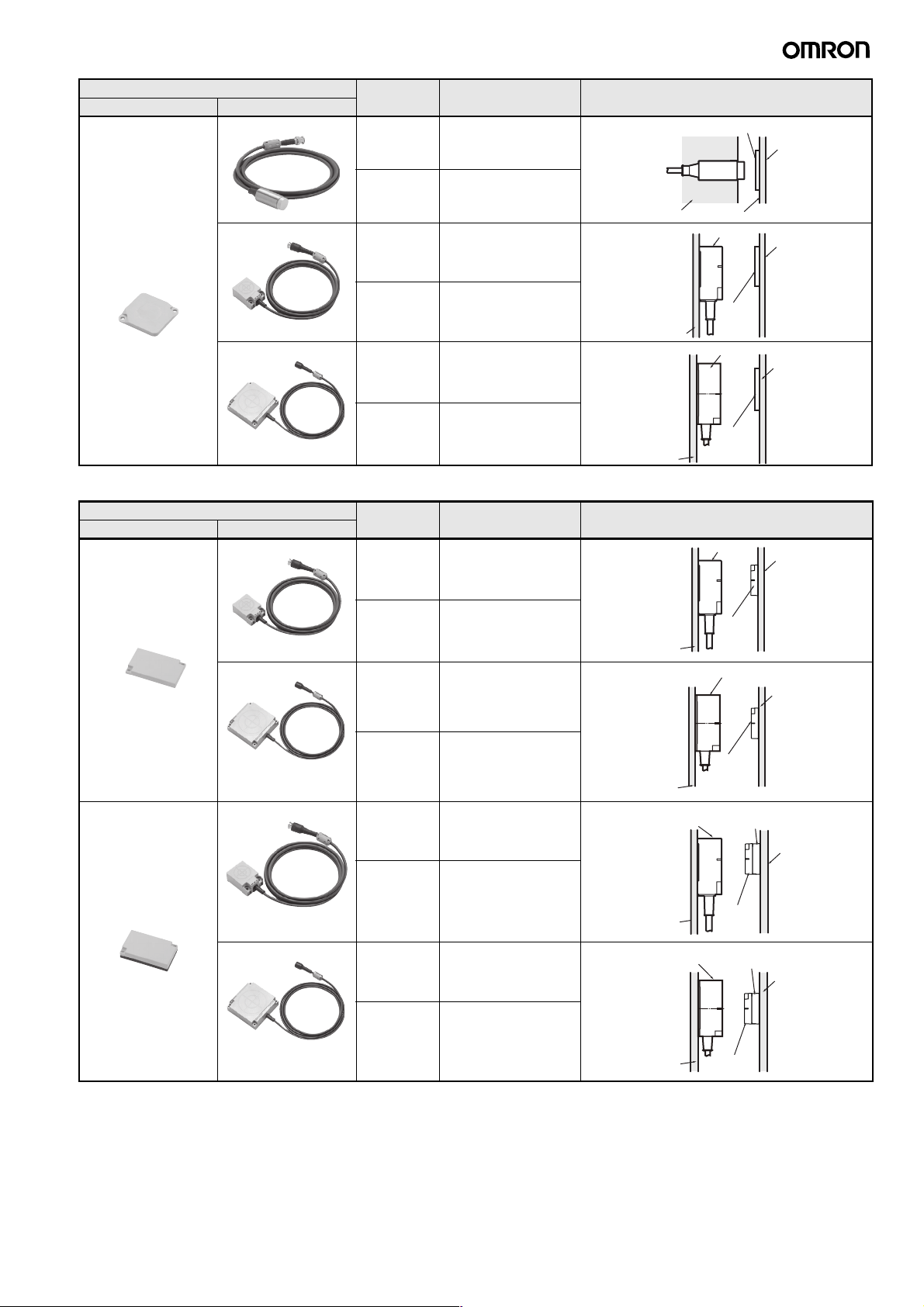
Recommended combination Function Transmission distance
ID Tag Read/Write Antenna
V680-D2KF67M (flushmounted on metallic
surface: steel)
V680-HS52 Read
distance
Write
distance
V680-HS63 Read
distance
(unit: mm)
1.0 to 16.0 mm
(axial deviation ±2)
1.0 to 16.0 mm
(axial deviation ±2)
6.0 to 25.0 mm
(axial deviation ±10)
ID Tag and Read/Write Antenna mounting
Non-metallic
conditions
V680-D2KF67M
V680-HS52
Iron
V680-HS63
Metallic
Metallic
Write
distance
V680-HS65 Read
distance
Write
distance
ID Tag (8-/32-Kbyte Memory) Transmission
Recommended combination Function Transmission distance
ID Tag Read/Write Antenna
V680-D8KF68/
-D32KF68
V680-D8KF68/
-D32KF68
(Special attachment
provided; flush-mounted
on metallic surface:
steel)
V680-HS63 Read
distance
Write
distance
V680-HS65 Read
distance
Write
distance
V680-HS63 Read
distance
Write
distance
6.0 to 25.0 mm
(axial deviation ±10)
5.0 to 25.0 mm
(axial deviation ±10)
5.0 to 25.0 mm
(axial deviation ±10)
(unit: mm)
5.0 to 45.0 mm
(axial deviation ±10)
(See note.)
5.0 to 45.0 mm
(axial deviation ±10)
(See note.)
5.0 to 75.0 mm
(axial deviation ±10)
(See note.)
5.0 to 75.0 mm
(axial deviation ±10)
(See note.)
5.0 to 35.0 mm
(axial deviation ±10)
5.0 to 35.0 mm
(axial deviation ±10)
V680D2KF67M
Non-metallic
V680-HS65
Metallic
V680D2KF67M
Metallic
ID Tag and Read/Write Antenna mounting
Metallic
Metallic
conditions
V680-HS63
V680-HS65
V680-HS63
V680-
@KF68
D
V680D@KF68
V680-A81
(ID Tag Attachment)
Non-metallic
(Resin, plastic, wood, etc.)
Non-metallic
(Resin, plastic, wood, etc.)
Metallic
V680-
Metallic
V680-HS65 Read
Note: When mounting the V680-HS65, be sure to attach the Mounting Brackets at the base of the Antenna.
The enclosed Mounting Brackets do not need to be used, however, if the mounting brackets on the Antenna are metal plates and their
dimensions are larger than the dimensions of the Antenna (100 × 100 mm).
For details, refer to the User's Manual (Cat. No. Z248 or Z262).
Note: The transmission distance may be reduced if the V680-D1KP66T or V680-D1KP58HT is mounted onto a metallic surface. Refer to the User's
Manual (V680-D1KP@@: Cat. No. Z262, V680-D1KP58HT: Cat. No. Z221) for details.
distance
Write
distance
5.0 to 55.0 mm
(axial deviation ±10)
5.0 to 55.0 mm
(axial deviation ±10)
V680-HS65
Metallic
D@KF68
V680-A81
(ID Tag Attachment)
V680D
@KF68
Metallic
V680-HAM42-DRT, V680-HAM91/-HAM81 15
Page 16
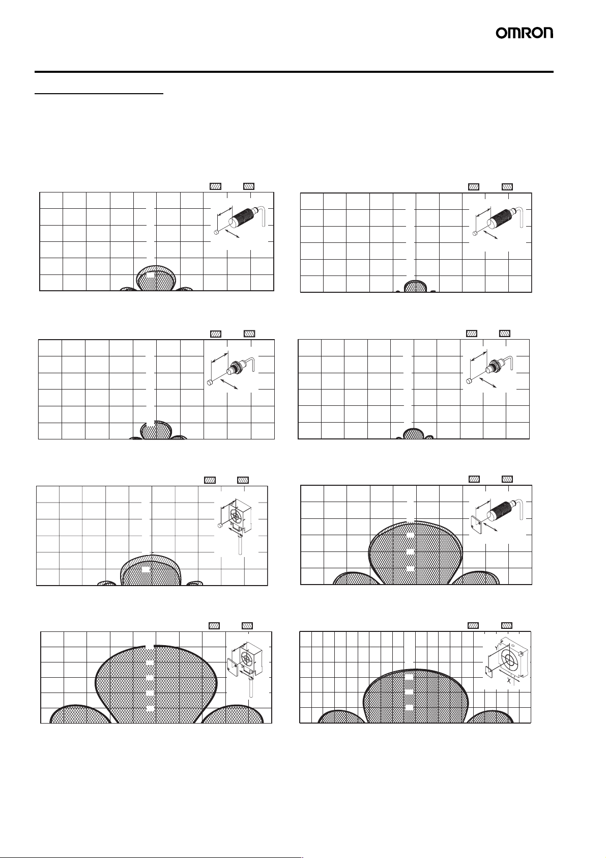
Characteristic Data (Typical)
Transmission Range (unit: mm)
1-kbyte Memory ID Tag
The values given for communications ranges are reference values. Refer to pages 11 to 13 for communications distance specifications.
The communications distance will depend on the ID Tags, ambient temperature, surrounding metal, noise, and other factors. Test operation
completely when installing a system.
V680-HS52 (embedded in non-metallic material) &
V680-D1KP52MT
Read
Y
50
40
30
20
10
010203040X−50 −40 −30 −20 −10
Y
X
V680-HS51 (embedded in metallic material) &
V680-D1KP52MT
Read
Y
50
40
30
20
10
010203040X−50 −40 −30 −20 −10
Y
X
V680-HS63 (mounted on non-metallic material) &
V680-D1KP52MT
Read
Y
50
40
30
20
10
Y
X
Write
Write
Write
V680-HS52 (embedded in non-metallic material) &
V680-D1KP52MT (embedded in metallic surface: steel)
Read
Y
50
40
30
20
10
010203040X−50 −40 −30 −20 −10
Y
Write
X
V680-HS51 (embedded in metallic material) &
V680-D1KP52MT (embedded in metallic surface: steel)
Read
Y
50
40
30
20
10
010203040X−50 −40 −30 −20 −10
Y
Write
X
V680-HS52 (embedded in non-metallic material) &
V680-D1KP66T
Read
Y
50
40
30
20
10
Y
Write
X
010203040X−50 −40 −30 −20 −10
V680-HS63 (mounted on non-metallic material) &
V680-D1KP66T
Y
50
40
30
20
10
010203040−50 −40 −30 −20 −10
Read
Y
X
Write
V680-HS65 (mounted on metallic material) &
V680-D1KP66T
X
−80−100 −20
16 V680-HAM42-DRT, V680-HAM91/-HAM81
0 10203040X−50 −40 −30 −20 −10
Y
100
80
60
40
20
−60 4020 X
−40
0
Read
60
Write
80
Page 17
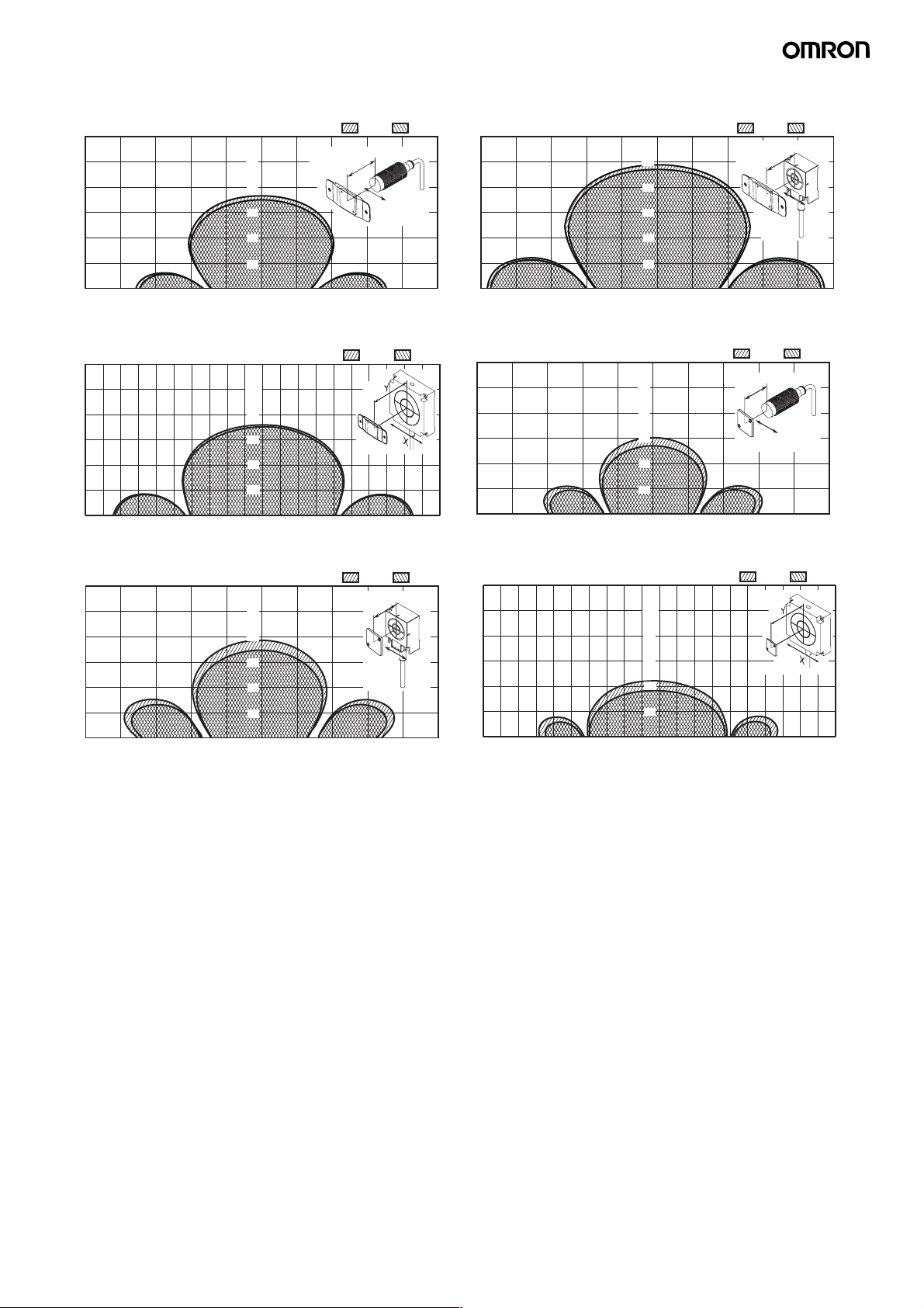
V680-HS52 (embedded in non-metallic material) &
V680-D1KP66T-SP
Read
Y
50
40
30
20
10
Y
X
Write
V680-HS63 (mounted on non-metallic material) &
V680-D1KP66T-SP
Read
Y
50
40
30
20
10
Y
X
Write
010203040X−50 −40 −30 −20 −10
V680-HS65 (mounted on metallic material) &
V680-D1KP66T-SP
Write
80
Y
100
80
60
40
20
−80−100 −20
−60 4020 X
−40
0
Read
60
V680-HS63 (mounted on non-metallic material) &
V680-D1KP66MT (flush-mounted on metallic surface: steel)
Read
Y
50
40
30
20
10
010203040X−50 −40 −30 −20 −10
Write
Y
X
010203040X−50 −40 −30 −20 −10
V680-HS52 (embedded in non-metallic material) &
V680-D1KP66MT (flush-mounted on metallic surface: steel)
Read
Y
50
40
30
20
10
010203040X−50 −40 −30 −20 −10
Y
Write
X
V680-HS65 (mounted on metallic material) &
V680-D1K66MT (flush-mounted on metallic surface: steel)
Y
100
80
60
40
20
−80−100 −20
−60 4020 X
−40
0
Read
60
Write
80
V680-HAM42-DRT, V680-HAM91/-HAM81 17
Page 18
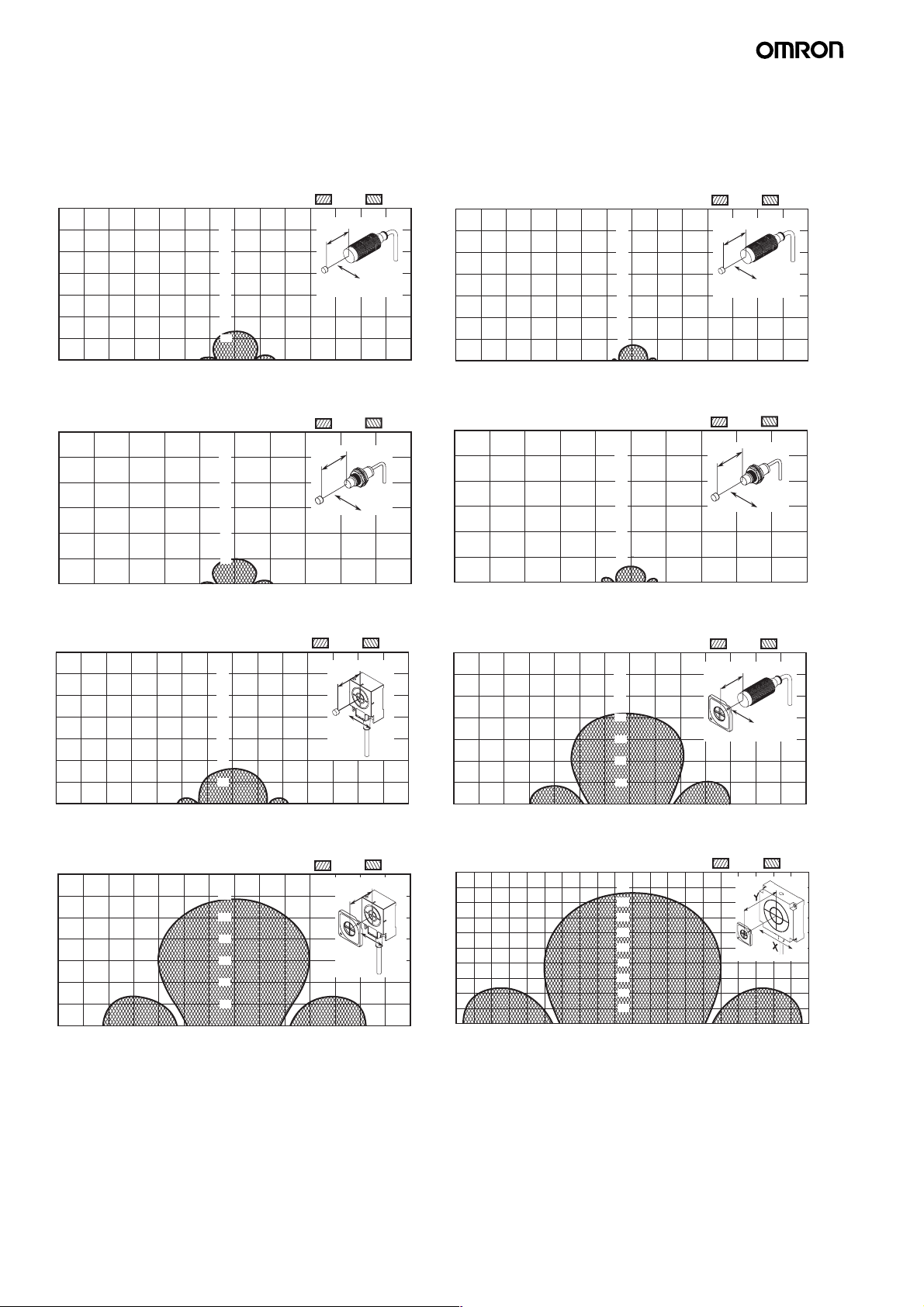
2-kbyte Memory ID Tag
The values given for communications ranges are reference values. Refer to pages 14 to 15 for communications distance specifications. The
communications distance will depend on the ID Tags, ambient temperature, surrounding metal, noise, and other factors. Test operation
completely when installing a system.
V680-HS52 (embedded in non-metallic material) &
V680-D2KF52M
Read
Y
60
50
40
30
20
10
0102030405060X−70 −60 −50 −40 −30 −20 −10
Y
X
V680-HS51 (embedded in metallic material) &
V680-D2KF52M
Read
Y
50
40
30
20
10
010203040X−50 −40 −30 −20 −10
Y
X
V680-HS63 (mounted on non-metallic material) &
V680-D2KF52M
Read
Y
60
50
40
30
20
10
Y
X
Write
Write
Write
V680-HS52 (embedded in non-metallic material) &
V680-D2KF52M (embedded in metallic surface: steel)
Read
Y
60
50
40
30
20
10
01020 30405060X−70 −60 −50 −40 −30 −20 −10
Y
Write
X
V680-HS51 (embedded in metallic material) &
V680-D2KF52M (embedded in metallic surface: steel)
Read
Y
Y
50
50
40
40
30
30
20
20
10
10
010203040X−50 −40 −30 −20 −10
Y
Write
X
V680-HS52 (embedded in metallic material) &
V680-D2KF67
Read
Y
60
50
40
30
20
10
Y
Write
X
010 2030405060X−70 −60 −50 −40 −30 −20 −10
V680-HS63 (mounted on non-metallic material) &
V680-D2KF67
Read
Y
60
50
40
30
20
10
0102030405060 X−70 −60 −50 −40 −30 −20 −10
Y
X
Write
V680-HS65 (mounted on metallic material) &
V680-D2KF67
−80−100 −20
18 V680-HAM42-DRT, V680-HAM91/-HAM81
0 1020 3040 50 60X−70 −60 −50 −40 −30 −20 −10
Y
90
80
70
60
50
40
30
20
10
−60 4020 X
−40
0
Read
60
Write
80
Page 19
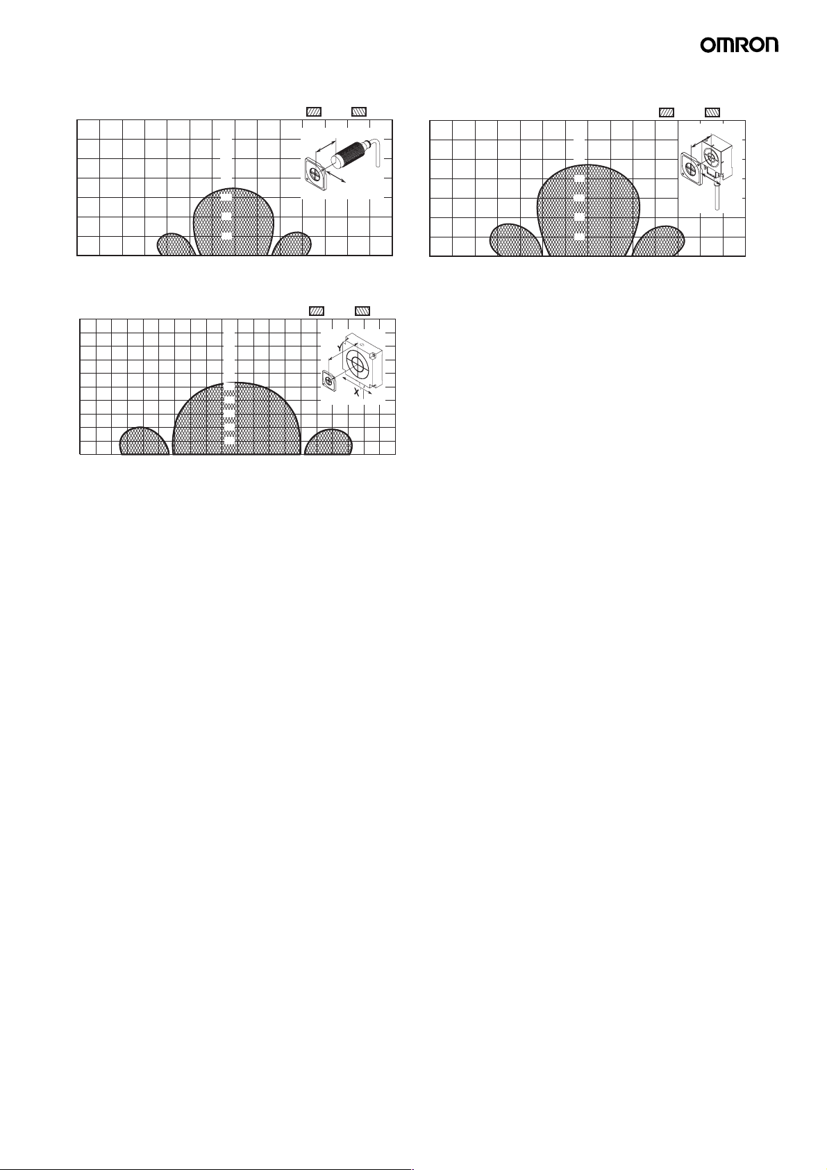
V680-HS52 (embedded in non-metallic material) &
V680-D2KF67M (flush-mounted on metallic surface: steel)
Read
Y
60
50
40
30
20
10
Y
Write
X
V680-HS63 (mounted on non-metallic material) &
V680-D2KF67M (flush-mounted on metallic surface: steel)
Read
Y
60
50
40
30
20
10
Write
Y
X
0102030405060X−70 −60 −50 −40 −30 −20 −10
V680-HS65 (mounted on metallic material) &
V680-D2KF67M (flush-mounted on metallic surface: steel)
Y
90
80
70
60
50
40
30
20
10
−80−100 −20
−60 4020 X
−40
0
Read
60
Write
80
0102030405060X−70 −60 −50 −40 −30 −20 −10
V680-HAM42-DRT, V680-HAM91/-HAM81 19
Page 20
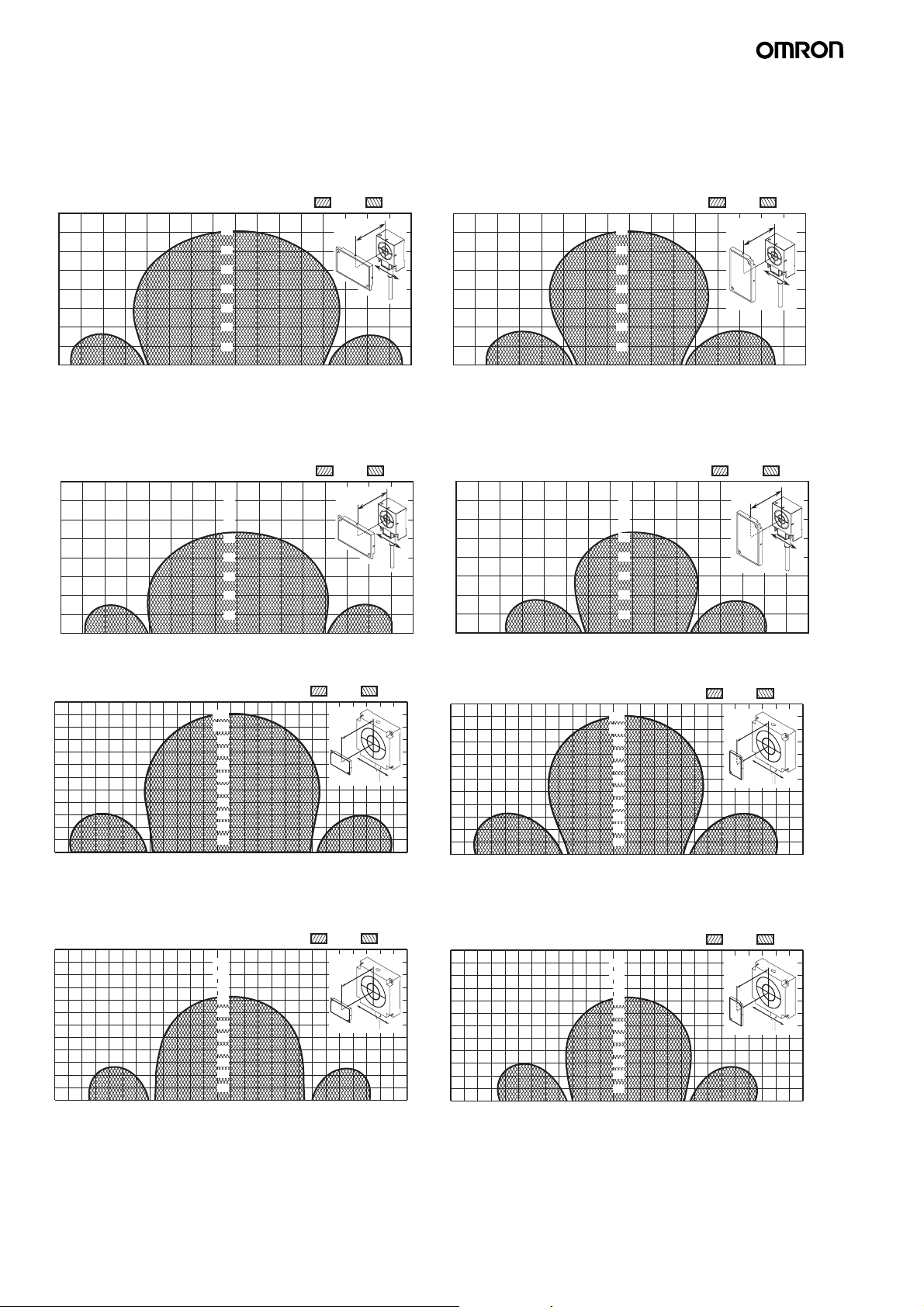
8-/32-Kbyte Memory ID Tag
The values given for communications ranges are reference values. Refer to pages 15 for communications distance specifications. The
communications distance will depend on the ID Tags, ambient temperature, surrounding metal, noise, and other factors. Test operation
completely when installing a system.
V680-HS63 (mounted on metallic material) &
V680-D8KF68/-D32KF68 (Horizontal-facing ID Tag)
Read
Y
70
60
50
40
30
20
10
0−80 −60 −50 −40 −30 −20 −10 10 20 30 40 50 60 70−70
Write
Y
X
X
V680-HS63 (mounted on metallic material) &
V680-D8KF68/-D32KF68
Flush-mounted on metallic surface: steel (Horizontalfacing ID Tag) When the V680-A81 ID Tag Attachment is
mounted.
Read
Y
70
60
50
40
30
20
10
Write
Y
X
X0−80 −60 −50 −40 −30 −20 −10 10 20 30 40 50 60 70−70
V680-HS65 (mounted on metallic material) &
V680-D8KF68/-D32KF68 (Horizontal-facing ID Tag)
Read
Y
110
100
90
80
70
60
50
40
30
20
10
0−120 −100 −80 −60 −40 −20 20 40 60 80 100 120 X
Write
Y
X
V680-HS65 (mounted on metallic material) &
V680-D8KF68/-D32KF68 Flush-mounted on metallic
surface: steel (Horizontal-facing ID Tag) When the
V680-A81 ID Tag Attachment is mounted.
Y
110
100
90
80
70
60
50
40
30
20
10
0−120 −100 −80 −60 −40 −20 20 40 60 80 100 120 X
Read
Write
Y
X
V680-HS63 (mounted on metallic material) &
V680-D8KF68/-D32KF68 (Vertical-facing ID Tag)
Read
Y
70
60
50
40
30
20
10
0−80 −60 −50 −40 −30 −20 −10 10 20 30 40 50 60 70−70 X
Write
Y
X
V680-HS63 (mounted on metallic material) &
V680-D8KF68/-D32KF68
Flush-mounted on metallic surface: steel (Vertical-facing
ID Tag) When the V680-A81 ID Tag Attachment is mounted.
Read
Y
70
60
50
40
30
20
10
Write
Y
X
X0−80 −60 −50 −40 −30 −20 −10 10 20 30 40 50 60 70−70
V680-HS65 (mounted on metallic material) &
V680-D8KF68/-D32KF68 (Vertical-facing ID Tag)
Read
Y
110
100
90
80
70
60
50
40
30
20
10
0−120 −100 −80 −60 −40 −20 20 40 60 80 100 120 X
Write
Y
X
V680-HS65 (mounted on metallic material) &
V680-D8KF68/-D32KF68 Flush-mounted on metallic
surface: steel (Vertical-facing ID Tag) When the
V680-A81 ID Tag Attachment is mounted.
Read
Y
110
100
90
80
70
60
50
40
30
20
10
0−120 −100 −80 −60 −40 −20 20 40 60 80 100 120 X
Write
Y
X
20 V680-HAM42-DRT, V680-HAM91/-HAM81
Page 21
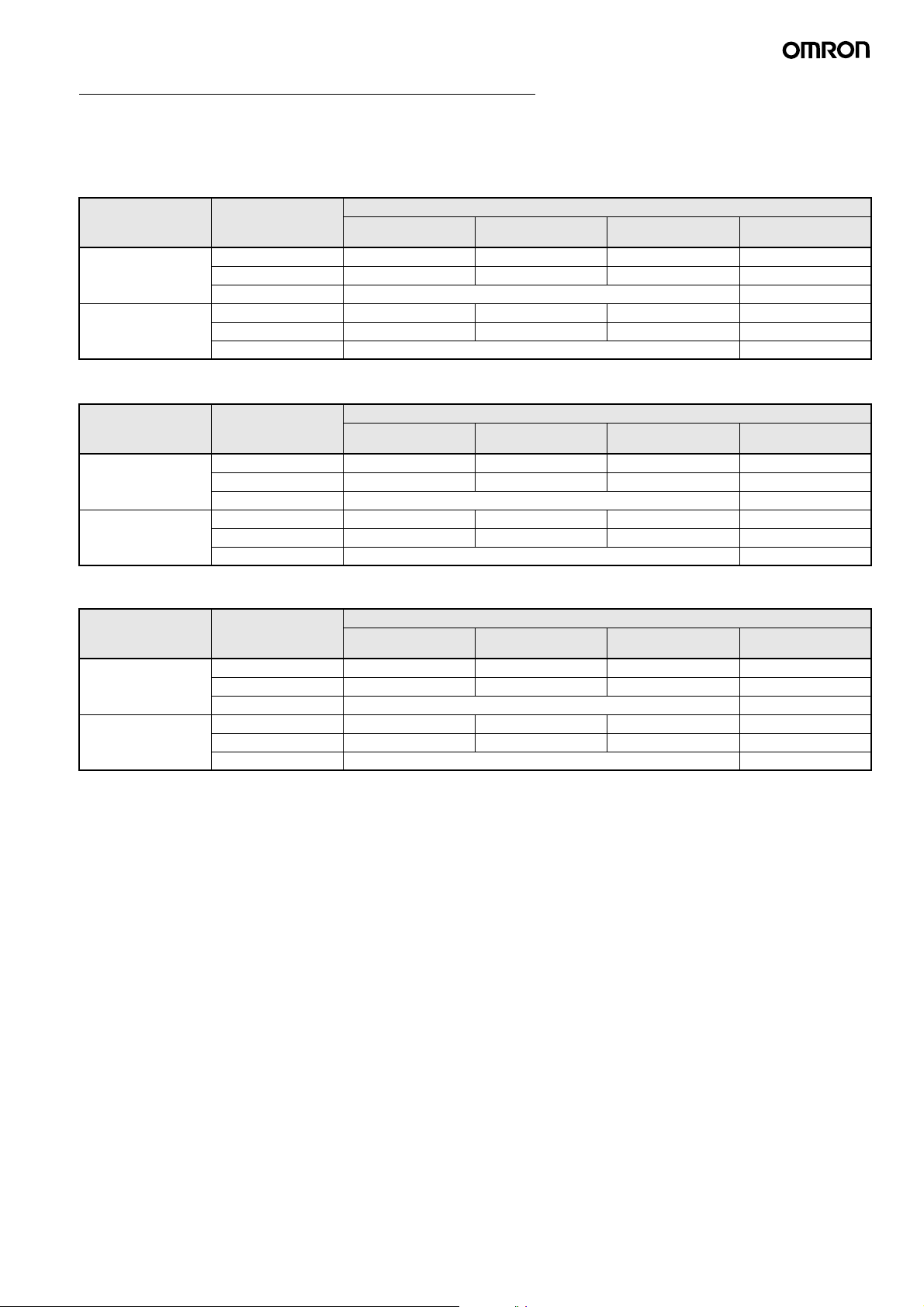
Processing Times (for reference purposes only)
Communications times between the Antenna and ID Tag, plus the processing time for the Amplifier.
V680-HAM42-DRT (DeviceNet ID Slave)
1-Kb Memory Tag
V680-D1KP@ (V680-HS@@ Antenna)
Communications
speed setting
Normal mode Read 67 95 137 67
High-speed mode Read 63 85 117 ---
2-Kb Memory Tag
V680-D2KF@ (V680-HS@@ Antenna)
Communications
speed setting
Normal mode Read 65 92 130 65
High-speed mode Read 61 81 110 ---
8 and 32-Kb Memory Tag
V680-D8KF68, V680-D32KF68 (V680-HS@@ Antenna)
Communications
speed setting
Normal mode Read 66 94 136 66
High-speed mode Read 59 76 102 ---
Command Communications time (ms)
4-byte Access Mode 26-byte Access Mode 58-byte Access Mode V600-compatible
Write (with verification) 105 143 210 105
Data Fill 17.5 × number of processed blocks + 89.2 ---
Write (with verification) 89 128 186 ---
Data Fill 14.8 × number of processed blocks + 71.7 ---
Command Communications time (ms)
4-byte Access Mode 26-byte Access Mode 58-byte Access Mode V600-compatible
Write (with verification) 105 142 219 105
Data Fill 17.5 × number of processed blocks + 89.2 ---
Write (with verification) 86 124 178 ---
Data Fill 14.8 × number of processed blocks + 71.7 ---
Command Communications time (ms)
4-byte Access Mode 26-byte Access Mode 58-byte Access Mode V600-compatible
Write (with verification) 96 131 182 96
Data Fill 17.5 × number of processed blocks + 89.2 ---
Write (with verification) 76 100 135 ---
Data Fill 14.8 × number of processed blocks + 71.7 ---
Mode
Mode
Mode
V680-HAM42-DRT, V680-HAM91/-HAM81 21
Page 22
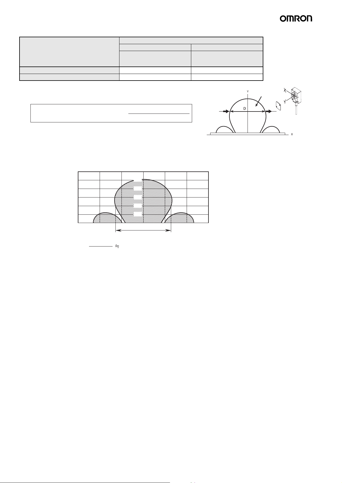
V680-HAM91/-HAM81 (ID Flag Sensor)
Model V680-HAM91/V680-HAM81
Read Write
Function (Mode)
1-Kb, 2-Kb Memory Tag 43 ms 87 ms
8-Kb, 32-Kb Memory Tag 50 ms 84 ms
ID Tag travel speed (i.e., conveyor speed) =
Data Read
Verify Read
Travel distance (D) in
communications area
Communications time (T)
BIT SET
BIT CLEAR
Direction
of travel
Calculation Example:
In this example, the V680-D1KP66T and V680-HS63 are combined and read together.
Y
50
40
30
20
10
Write
Communications
range
−30 −20 −10 0 20 40 X
50 mm
ID Tag travel speed (m/min.) =
Note 1. The travel speed depends on communications distance Y and axis offset. It is recommended to refer to the communications area diagram
and use the part with the widest area.
2. These values are guidelines. Perform testing with the actual device before operation.
3. Processing for communications errors is not included in this formula.
50 (mm)
43 (ms)
69 (m/min)
(Unit: mm)
22 V680-HAM42-DRT, V680-HAM91/-HAM81
Page 23
Safety Precautions
WARNING
Do not use this product as a detection device to protect
people.
Note: This catalog is intended only to help select the appropriate
product. Be sure to read the User's Manual for usage
precautions prior to using the product.
Precautions for Safe Use
To ensure safety, be sure to follow the following precautions:
1. Do not operate this product in any flammable, explosive, or corrosive gas environment.
2. Do not disassemble, repair, or remodel this product.
3. If any cable has a locking mechanism, be sure to check that it has
been locked before using it.
4. The DC power supply must be within the specified rating (24 VDC
+10%/−15%).
5. Do not reverse the power supply connection.
6. Do not insert water, wire, etc., into any of the gaps in the case.
Doing so may cause fire or electric shock.
7. Make sure that the Unit is provided with sufficient ventilation
space.
8. Do not install the Products near any equipment that generates a
large amount of heat (such as heaters, transformers, and largecapacity resistors).
9. Turn OFF the Controller or ID Sensor Unit power before attaching
or removing the Read/Write Antenna.
10.In the event that the product exhibits any abnormal condition,
immediately stop using the system, turn OFF the power, and contact your OMRON sales representative.
11.Dispose of this product as industrial waste.
12.Do not clean the Products with paint thinner, benzene, acetone,
or kerosene.
13.If multiple Antennas are mounted near each other, communications performance may decrease due to mutual interference.
Refer to the User's Manual (Cat. No. Z278 or Z279) and check to
make sure there is no mutual interference between the Antennas.
14.To remove the Unit, catch a tool on the hook and gently remove
the Unit.
15.Do not perform wiring incorrectly or short-circuit the load. Doing
so may result in rupture or damage from burning.
16.Do not use the product in environments subject to oil.
17.Do not use the product with an AC power supply.
Precautions for Correct Use
Please observe the following precautions to prevent failure to
operate, malfunctions, or undesirable effects on product
performance.
Installation Site
Install the product at a location where:
• It is not exposed to corrosive gases, dust, metal chips, or salt.
• The ambient operating temperature is within the range stipulated in
the specifications.
• There are no sudden variations in temperature (no condensation).
• The ambient operating humidity is within the range stipulated in the
specifications.
• No vibration or shock exceeding the values stipulated in the
specifications is transmitted directly to the body of the product.
• It is not subject to splashing water, oil, or chemical substances.
Installation
• The product uses the 13.56-MHz frequency band to communicate
with ID Tags. Some devices, such as some motors, inverters, and
switching power supplies, generate electromagnetic waves (i.e.,
noise) that can affect communications with ID Tags. If any of these
devices are nearby, communications with ID Tags may be affected
or ID Tags may be destroyed. If the product is to be used near such
devices, check the effects on communications before using the
product.
• To minimize the general influence of noise, observe the following
precautions:
1. Ground any metallic material located around this device to
100 Ω or less.
2. Keep the product away from high voltage and heavy current.
• Always bundle the cables connected to the power supply terminals
and the ground terminal and connect the enclosed ferrite core
(ZCAT2032-0930 manufactured by TDK) (V680-HAM42-DRT
only).
• Do not pull on the cables with excessive strength.
• Do not use products that are not waterproof in misty environments.
• Do not subject the products to chemicals that adversely affect
product materials.
• When installing the product, tighten screws to the following torque:
V680-HS51 Read/Write Antenna: 6 N·m
V680-HS52 Read/Write Antenna: 40 N·m
V680-HS63 Read/Write Antenna: 1.2 N·m
V680-HS65 Read/Write Antenna: 0.7 to 1.2 N·m
• When Read/Write Antennas are mounted side-by-side, mutual
interference may reduce the transmission performance. Refer to
the RFID System Amplifier and Antennas/ID Tags User's Manual to
mount them in a way that will prevent mutual interference.
Host Communications (V680-HAM91/-HAM81)
When the Product is started, unstable signals may be output from
the host interface.
Begin performing controls with the Product only after it has been
started for at least 1 second.
Storage
Store the product at a location where:
• It is not exposed to corrosive gases, dust, metal chips, or salt.
• The ambient storage temperature is within the range stipulated in
the specifications.
• There are no sudden variations in temperature (no condensation).
• The ambient storage humidity is within the range stipulated in the
specifications.
• No vibration or shock exceeding the values stipulated in the
specifications is transmitted directly to the body of the product.
• It is not subject to splashing water, oil, or chemical substances.
Cleaning
Do not use thinner, benzene, acetone, or kerosene for cleaning.
Using these substances may dissolve the resin material and the
case.
V680-HAM42-DRT, V680-HAM91/-HAM81 23
Page 24
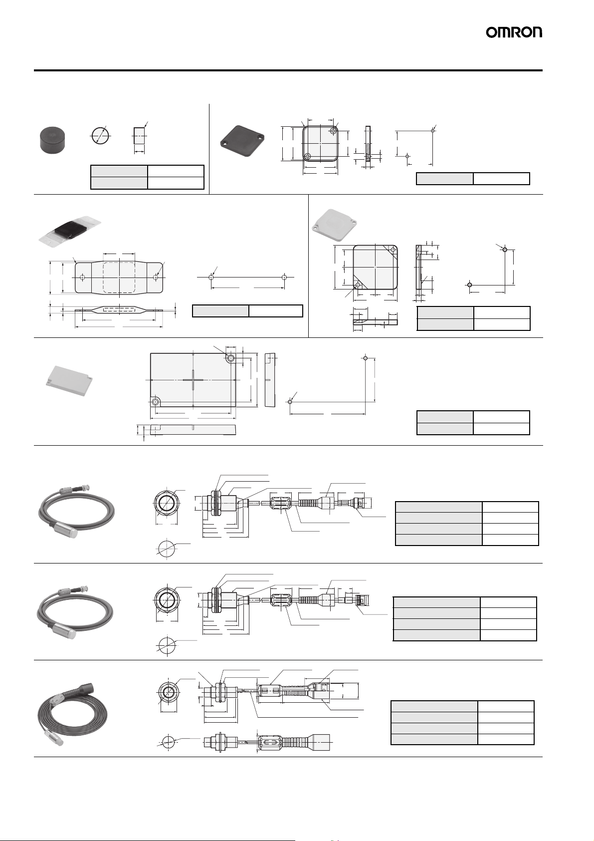
Dimensions
Note: All units are in millimeters unless otherwise indicated.
ID Tag
V680-D1KP52MT/-D2KF52M
0
dia.
8
−0.1
R0.2
0
5
−0.1
Case material PPS resin
Filling Epoxy resin
V680-D1KP66T/-D1KP66MT
34
Four, R4
32
25
Two ,
±0.2
25
32
34
Two ,
6 dia.
3.5 dia.
3.5
±0.2
25
±0.1
Two , M 3
±0.2
25
Case material PPS resin
±0.2
Mounting Hole Dimensions
Four, R3
V680-D1KP66T-SP
Four, R6
36.5
34
6.5
2.5 max.
34
80±0.2
95
V680-D8KF68/-D32KF68
10
Two, 5.5 dia.
(mounting holes)
1.3
Two, 4.5 dia. mounting holes
76
5
Mounting Hole Dimensions
Two , M 5
80±0.2
Case material PFA resin
10
10
54
±0.2
44
±0.2
86
Mounting Hole Dimensions
Two , M 4
Read/Write Antenna with Detachable Amplifier Unit
V680-HS52-W
35 dia.
19.8 dia.
Mounting Hole Dimensions
30
22.5 dia.
Two toothed washers
7
47.6
50
57
65
Two mounting nuts
M22 × 1
16.5 dia.
Operation indicator
30
5.5-dia. coaxial cable
Ferrite core
V680-D2KF67/-D2KF67M
16
+0.1
40
−0.5
16
16
Two, 3.5-dia.
mounting holes
76
Insulated cover
50
16.5 dia.
5.2
37
13.2
8
Connector
16
+0.1
40
−0.5
8
0.2
44
14.5 dia.
Case material Brass
Transmission surface PBT resin
Filling Epoxy resin
Cable PVC
Mounting Hole Dimensions
5.2
8
13.2
Mounting reference
surface
8
2
4.5
Two , M 3
32
±0.2
Case material ABS resin
Filling Epoxy resin
Case material PBT resin
Filling Epoxy resin
±0.2
32
V680-HS52-R
V680-HS51
35 dia.
19.8 dia.
Mounting Hole Dimensions
30
22.5 dia.
M12 × 1
21 dia.
9.6 dia.
17
Mounting Hole Dimensions
12.5 dia.
7
47.6
50
57
7
24
33
35
Two toothed washers
Two mounting nuts
M22 × 1
65
Toothed washer
Two mounting nuts
12
Coaxial cable, 2.9 dia., Standard length: 2 m
15
Operation indicator
30
16.5 dia.
25
5.3-dia. coaxial cable
Ferrite core
Ferrite core
50
50
26.2
24 V680-HAM42-DRT, V680-HAM91/-HAM81
Insulated cover
20
10
16.5 dia.
Connector
(14.5 dia.)
Insulated cover
14.5 dia.
Connector
(16.8 dia.)
Case material Brass
Transmission surface PBT resin
Filling Epoxy resin
Cable PVC
Case material Brass
Transmission surface ABS resin
Filling Epoxy resin
Cable PVC
Page 25
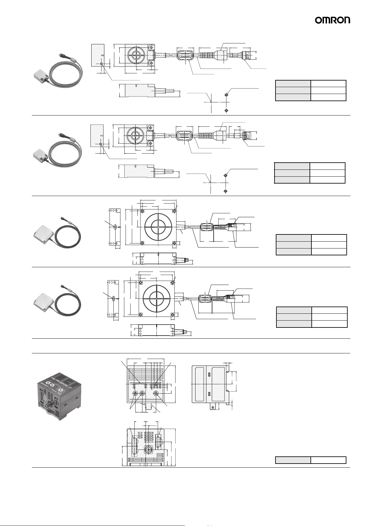
V680-HS63-W
5
40
±0.1
28
5
Operation indicator
23
Insulated cover
30
16.5 dia.
6
27
53
Mounting Hole Dimensions
Center of coil
11
50
16.5 dia.
5.5-dia. coaxial cable
Ferrite core
37
14.5 dia.
Connector
Two, M4 or 4.5 dia.
Case material ABS resin
Filling Epoxy resin
Cable PVC
V680-HS63-R
V680-HS65-W
V680-HS65-R
5
Operation
indicator
Operation
indicator
40
±0.1
28
5
Operation indicator
23
14
100
14
100
Insulated cover
30
16.5 dia.
6
27
53
50
16.5 dia.
5.3-dia. coaxial cable
Ferrite core
Mounting Hole Dimensions
Center of coil
11
20
10
14.5 dia.
Connector
Two, M4 or 4.5 dia.
Case material ABS resin
Filling Epoxy resin
Cable PVC
5
5
50
±0.2
90
30
20
5
5
50
±0.2
90
30
20
100
±0.2
90
50
100
±0.2
90
50
Four, 4.5-dia.
(Mounting holes)
25
Bushing
10
10
Four, 4.5-dia.
(Mounting holes)
25
Bushing
10
10
16.5 dia.
30
5.5-dia. coaxial cable
11
16.5 dia.
30
5.3-dia. coaxial cable
11
Ferrite core
Ferrite core
(39.5)
50
37
50
Connector
14.5 dia.
Insulated cover
Connector
14.5 dia.
16.8 dia.
Insulated cover
16.8 dia.
Case material ABS resin
Filling Epoxy resin
Cable PVC (gray)
Case material ABS resin
Filling Epoxy resin
Cable PVC (black)
Amplifier: DeviceNet ID Slave
V680-HAM42-DRT
Operation
indicators
Node address
switches
DeviceNet Connector
53
20
12
20.5
65
10
6
18
21.5
5.06
Data indicators
5
5
1.5
65
16
4
Mode switch
Antenna connector
Power supply terminals
5
6
1
84.
825
.
5
22.6
35.2
12
(3.7)
Case material PC+ABS resin
V680-HAM42-DRT, V680-HAM91/-HAM81 25
Page 26
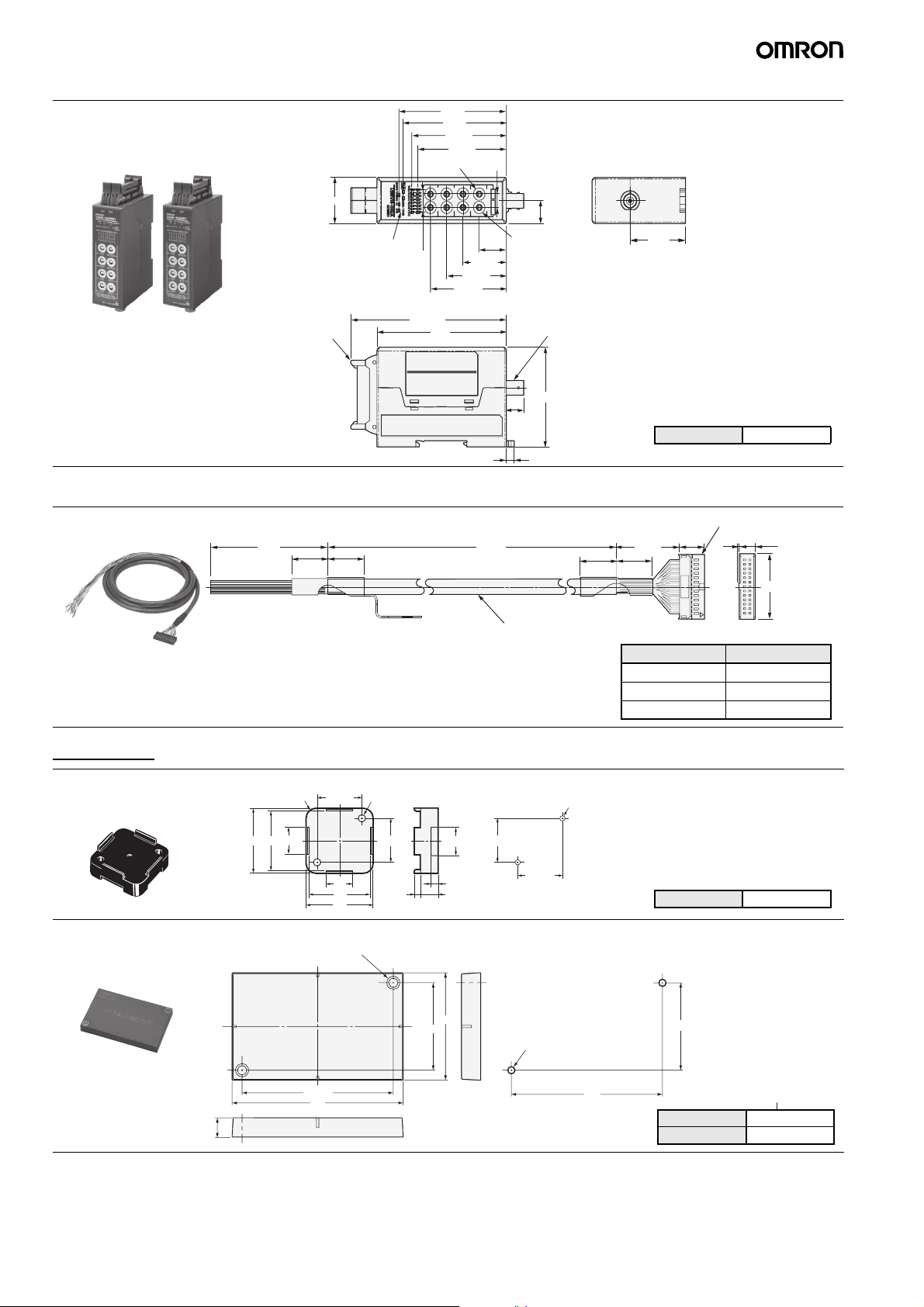
Amplifier: ID Flag Sensor
V680-HAM91/-HAM81
74. 8
71.8
65. 75
61.7 5
4 switches
7.
8
Connector
Interface Cable (Order Separately)
V680-A60 2M/5M/10M
320
±5
20
Note: The connectors are not water resistant.
03
21 operation indicators
20
.2x7
±5
7.41=1
108.26
47.41
4 switches
18. 95
30. 25
41.55
52. 85
90
Connector
56
12
38.5
Case material PC+ABS resin
(5.5)
Connector: XG5M-2632-N
+50
L1
0
9-dia. (0.2-dia per 7 conductors)
vinyl-insulated round cable with 23 conductors
±5
20
14.4
±5
35
±5
20
6.1
1
6.73
Model Length L1 (mm)
V680-A60 2M 2,000 mm
V680-A60 5M 5,000 mm
V680-A60 10M 10,000 mm
Accessory
V680-D1KP66T Attachments
V600-A86 Holder
37
Four, R5.5
15
34
±0.2
25
Two, 4-dia.
±0.2
25
15
34
37
3.5
V680-D8KF68/-D32KF68 Attachments
Mounting holes
V600-A81 Holder
10
Two, 4.5-dia.
±0.2
76
86
44
26 V680-HAM42-DRT, V680-HAM91/-HAM81
Mounting Hole Dimensions
25
16
4
10
54
±0.2
±0.2
Two , M 3
±0.2
25
Mounting Hole Dimensions
Two, M4
76
Case material PPS resin
44
Case material PBT resin
Filling Epoxy resin
Page 27

V680-HAM42-DRT, V680-HAM91/-HAM81 27
Page 28

READ AND UNDERSTAND THIS DOCUMENT
Please read and understand this document before using the products. Please consult your OMRON representative if you have any questions or comments.
WARRANTY
OMRON’s exclusive warranty is that the products are free from defects in materials and workmanship for a period of one year (or other period if specified) from date of sale by
OMRON.
OMRON MAKES NO WARRANTY OR REPRESENTATION, EXPRESS OR IMPLIED, REGARDING NON-INFRINGEMENT, MERCHANTABILITY, OR FITNESS FOR
PARTICULAR PURPOSE OF THE PRODUCTS. ANY BUYER OR USER ACKNOWLEDGES THAT THE BUYER OR USER ALONE HAS DETERMINED THAT THE PRODUCTS
WILL SUITABLY MEET THE REQUIREMENTS OF THEIR INTENDED USE. OMRON DISCLAIMS ALL OTHER WARRANTIES, EXPRESS OR IMPLIED.
LIMITATIONS OF LIABILITY
OMRON SHALL NOT BE RESPONSIBLE FOR SPECIAL, INDIRECT, OR CONSEQUENTIAL DAMAGES, LOSS OF PROFITS OR COMMERCIAL LOSS IN ANY WAY
CONNECTED WITH THE PRODUCTS, WHETHER SUCH CLAIM IS BASED ON CONTRACT, WARRANTY, NEGLIGENCE, OR STRICT LIABILITY.
In no event shall responsibility of OMRON for any act exceed the individual price of the product on which liability is asser ted.
IN NO EVENT SHALL OMRON BE RESPONSIBLE FOR WARRANTY, REPAIR, OR OTHER CLAIMS REGARDING THE PRODUCTS UNLESS OMRON’S ANALYSIS
CONFIRMS THAT THE PRODUCTS WERE PROPERLY HANDLED, STORED, INSTALLED, AND MAINTAINED AND NOT SUBJECT TO CONTAMINATION, ABUSE, MISUSE,
OR INAPPROPRIATE MODIFICATION OR REPAIR.
SUITABILITY FOR USE
THE PRODUCTS CONTAINED IN THIS DOCUMENT ARE NOT SAFETY RATED. THEY ARE NOT DESIGNED OR RATED FOR ENSURING SAFETY OF PERSONS, AND
SHOULD NOT BE RELIED UPON AS A SAFETY COMPONENT OR PROTECTIVE DEVICE FOR SUCH PURPOSES. Please refer to separate catalogs for OMRON's safety rated
products.
OMRON shall not be responsible for conformity with any standards, codes, or regulations that apply to the combination of products in the customer’s application or use of the
product.
At the customer’s request, OMRON will provide applicable third party certification documents identifying ratings and limitations of use that apply to the products. This information by
itself is not sufficient for a complete determination of the suitability of the products in combination with the end product, machine, system, or other application or use.
The following are some examples of applications for which particular attention must be given. This is not intended to be an exhaustive list of all possible uses of the products, nor is
it intended to imply that the uses listed may be suitable for the products:
• Outdoor use, uses involving potential chemical contamination or electrical interference, or conditions or uses not described in this document.
• Nuclear energy control systems, combustion systems, railroad systems, aviation systems, medical equipment, amusement machines, vehicles, safety equipment, and
installations subject to separate industry or government regulations.
• Systems, machines, and equipment that could present a risk to life or property.
Please know and observe all prohibitions of use applicable to the products.
NEVER USE THE PRODUCTS FOR AN APPLICATION INVOLVING SERIOUS RISK TO LIFE OR PROPERTY WITHOUT ENSURING THAT THE SYSTEM AS A WHOLE HAS
BEEN DESIGNED TO ADDRESS THE RISKS, AND THAT THE OMRON PRODUCT IS PROPERLY RATED AND INSTALLED FOR THE INTENDED USE WITHIN THE OVERALL
EQUIPMENT OR SYSTEM.
PERFORMANCE DATA
Performance data given in this document is provided as a guide for the user in determining suitability and does not constitute a warranty. It may represent the result of OMRON’s
test conditions, and the users must correlate it to actual application requirements. Actual performance is subject to the OMRON Warranty and Limitations of Liability.
CHANGE IN SPECIFICATIONS
Product specifications and accessories may be changed at any time based on improvements and other reasons.
It is our practice to change model numbers when published ratings or features are changed, or when significant construction changes are made. However, some specifications of
the product may be changed without any notice. When in doubt, special model numbers may be assigned to fix or establish key specifications for your application on your request.
Please consult with your OMRON representative at any time to confirm actual specifications of purchased products.
DIMENSIONS AND WEIGHTS
Dimensions and weights are nominal and are not to be used for manufacturing purposes, even when tolerances are shown.
ERRORS AND OMISSIONS
The information in this document has been carefully checked and is believed to be accurate; however, no responsibility is assumed for clerical, typographical, or proofreading
errors, or omissions.
PROGRAMMABLE PRODUCTS
OMRON shall not be responsible for the user’s programming of a programmable product, or any consequence thereof.
COPYRIGHT AND COPY PERMISSION
This document shall not be copied for sales or promotions without permission.
This document is protected by copyright and is intended solely for use in conjunction with the product. Please notify us before copying or reproducing this document in any manner,
for any other purpose. If copying or transmitting this document to another, please copy or transmit it in its entirety.
ALL DIMENSIONS SHOWN ARE IN MILLIMETERS.
To convert millimeters into inches, multiply by 0.03937. To convert grams into ounces, multiply by 0.03527.
OMRON Corporation
Industrial Automation Company
Sensing Devices Division H.Q.
Industrial Sensors Division
Shiokoji Horikawa, Shimogyo-ku,
Kyoto, 600-8530 Japan
Tel: (81)75-344-7022/Fax: (81)75-344-7107
Regional Headquarters
OMRON EUROPE B.V.
Sensor Business Unit
Carl-Benz-Str. 4, D-71154 Nufringen,
Germany
Tel: (49) 7032-811-0/Fax: (49) 7032-811-199
OMRON Industrial Automation Global: www.ia.omron.com
OMRON ELECTRONICS LLC
One Commerce Drive Schaumburg,
IL 60173-5302 U.S.A.
Tel: (1) 847-843-7900/Fax: (1) 847-843-7787
OMRON ASIA PACIFIC PTE. LTD.
No. 438A Alexandra Road # 05-05/08 (Lobby 2),
Alexandra Technopark, Singapore 119967
Tel: (65) 6835-3011/Fax: (65) 6835-2711
OMRON (CHINA) CO., LTD.
Room 2211, Bank of China Tower,
200 Yin Cheng Zhong Road,
PuDong New Area, Shanghai, 200120, China
Tel: (86) 21-5037-2222/Fax: (86) 21-5037-2200
Authorized Distributor:
In the interest of product improvement,
specifications are subject to change without notice.
Cat. No. Q160-E1-01
Printed in Japan
0308-0.3C (0308) (C)
 Loading...