


 Loading...
Omron V640-HAM11-V3, V640-HAM11-L, V700-L22, V640-HS62, V700-L11 User Manual
...CIDRW SYSTEM
V640 SERIES
USER'S MANUAL
AMPLIFIER UNITS
V640-HAM11-V3
V640-HAM11-L
CIDRW HEADS
V640-HS61
V640-HS62
CIDRW CONTROLLER
V700-L22
LINK UNIT
V700-L11
Cat. No. Z307-E1-02

Introduction
Thank you for purchasing the V640-series CIDRW System.
Please observe the following points when operating the V640-series CIDRW System:
•Allow the CIDRW System to be installed and operated only by qualified specialist with a sufficient knowledge of electrical systems.
•Please read and understand the contents of this manual before using the system.
•After reading this manual, store it in a convenient location for easy reference whenever necessary.

Introduction Table of Contents/Precautions in Using the Products
SECTION 1 Product Outline
SECTION 2 Installation and Connections/Wiring
SECTION 3 Preparing for Communications
SECTION 4 Reading from/Writing to ID Tags
SECTION 5 Troubleshooting
SECTION 6 Appendix
CIDRW System
V640-HAM11-V3 |
Amplifier Unit |
V640-HAM11-L |
Amplifier Unit |
V640-HS61 |
CIDRW Head |
V640-HS62 |
CIDRW Head |
V700-L22 |
CIDRW Controller |
V700-L11 |
Link Unit |
6 SECTION 5 SECTION 4 SECTION 3 SECTION 2 SECTION 1 SECTION INTRODUCTION
User's Manual

product the using in Precautions INTRODUCTION
INTRODUCTION
READ AND UNDERSTAND THIS DOCUMENT
Please read and understand this document before using the products. Please consult your OMRON representative if you have any questions or comments.
WARRANTY
OMRON’s exclusive warranty is that the products are free from defects in materials and workmanship for a period of one year (or other period if specified) from date of sale by OMRON.
OMRON MAKES NO WARRANTY OR REPRESENTATION, EXPRESS OR IMPLIED, REGARDING NONINFRINGEMENT, MERCHANTABILITY, OR FITNESS FOR PARTICULAR PURPOSE OF THE PRODUCTS. ANY BUYER OR USER ACKNOWLEDGES THAT THE BUYER OR USER ALONE HAS DETERMINED THAT THE PRODUCTS WILL SUITABLY MEET THE REQUIREMENTS OF THEIR INTENDED USE. OMRON DISCLAIMS ALL OTHER WARRANTIES, EXPRESS OR IMPLIED.
LIMITATIONS OF LIABILITY
OMRON SHALL NOT BE RESPONSIBLE FOR SPECIAL, INDIRECT, OR CONSEQUENTIAL DAMAGES, LOSS OF PROFITS OR COMMERCIAL LOSS IN ANY WAY CONNECTED WITH THE PRODUCTS, WHETHER SUCH CLAIM IS BASED ON CONTRACT, WARRANTY, NEGLIGENCE, OR STRICT LIABILITY.
In no event shall responsibility of OMRON for any act exceed the individual price of the product on which liability is asserted.
IN NO EVENT SHALL OMRON BE RESPONSIBLE FOR WARRANTY, REPAIR, OR OTHER CLAIMS REGARDING THE PRODUCTS UNLESS OMRON’S ANALYSIS CONFIRMS THAT THE PRODUCTS WERE PROPERLY HANDLED, STORED, INSTALLED, AND MAINTAINED AND NOT SUBJECT TO CONTAMINATION, ABUSE, MISUSE, OR INAPPROPRIATE MODIFICATION OR REPAIR.
SUITABILITY FOR USE
THE PRODUCTS CONTAINED IN THIS DOCUMENT ARE NOT SAFETY RATED. THEY ARE NOT DESIGNED OR RATED FOR ENSURING SAFETY OF PERSONS, AND SHOULD NOT BE RELIED UPON AS A SAFETY COMPONENT OR PROTECTIVE DEVICE FOR SUCH PURPOSES. Please refer to separate catalogs for OMRON's safety rated products.
OMRON shall not be responsible for conformity with any standards, codes, or regulations that apply to the combination of products in the customer’s application or use of the product.
At the customer’s request, OMRON will provide applicable third party certification documents identifying ratings and limitations of use that apply to the products. This information by itself is not sufficient for a complete determination of the suitability of the products in combination with the end product, machine, system, or other application or use.
The following are some examples of applications for which particular attention must be given. This is not intended to be an exhaustive list of all possible uses of the products, nor is it intended to imply that the uses listed may be suitable for the products:
•Outdoor use, uses involving potential chemical contamination or electrical interference, or conditions or uses not described in this document.
•Nuclear energy control systems, combustion systems, railroad systems, aviation systems, medical equipment, amusement machines, vehicles, safety equipment, and installations subject to separate industry or government regulations.
•Systems, machines, and equipment that could present a risk to life or property.
Please know and observe all prohibitions of use applicable to the products.
NEVER USE THE PRODUCTS FOR AN APPLICATION INVOLVING SERIOUS RISK TO LIFE OR PROPERTY WITHOUT ENSURING THAT THE SYSTEM AS A WHOLE HAS BEEN DESIGNED TO ADDRESS THE RISKS, AND THAT THE OMRON PRODUCT IS PROPERLY RATED AND INSTALLED FOR THE INTENDED USE WITHIN THE OVERALL EQUIPMENT OR SYSTEM.
2 |
|
CIDRW System |
|
||
|
User’s Manual |
|
|
|
|

INTRODUCTION
PERFORMANCE DATA
Performance data given in this document is provided as a guide for the user in determining suitability and does not constitute a warranty. It may represent the result of OMRON’s test conditions, and the users must correlate it to actual application requirements. Actual performance is subject to the OMRON Warranty and Limitations of Liability.
CHANGE IN SPECIFICATIONS
Product specifications and accessories may be changed at any time based on improvements and other reasons.
It is our practice to change model numbers when published ratings or features are changed, or when significant construction changes are made. However, some specifications of the product may be changed without any notice. When in doubt, special model numbers may be assigned to fix or establish key specifications for your application on your request. Please consult with your OMRON representative at any time to confirm actual specifications of purchased products.
DIMENSIONS AND WEIGHTS
Dimensions and weights are nominal and are not to be used for manufacturing purposes, even when tolerances are shown.
ERRORS AND OMISSIONS
The information in this document has been carefully checked and is believed to be accurate; however, no responsibility is assumed for clerical, typographical, or proofreading errors, or omissions.
PROGRAMMABLE PRODUCTS
OMRON shall not be responsible for the user’s programming of a programmable product, or any consequence thereof.
COPYRIGHT AND COPY PERMISSION
This document shall not be copied for sales or promotions without permission.
This document is protected by copyright and is intended solely for use in conjunction with the product. Please notify us before copying or reproducing this document in any manner, for any other purpose. If copying or transmitting this document to another, please copy or transmit it in its entirety.
product the using in Precautions INTRODUCTION
CIDRW System |
3 |
User’s Manual |

product the using in Precautions INTRODUCTION
INTRODUCTION
To Users of the V700-L21 CIDRW Controller
The V700-L22 CIDRW Controller complies with the 2003 edition of the SEMI E99 standard. The V700-
L21 CIDRW Controller cannot simply be replaced with the V700-L22. To replace the V700-L21 with the V700-L22, the control programming for the CIDRW Controller must be updated as described in this manual.
■ Main Differences from the V700-L21
• Added Attributes
The CIDRW attributes defined as CarrierIDOffset and CarrierIDlength in the 2003 edition of the SEMI E99 standard have been added. With the V700-L22, the user can now specify as attributes the position of the MID in the ID Tag, and the data length.
Refer to Support Attributes p.158.
• Changed Message Specifications
The 2003 edition of SEMI E99 adds a format definition for the data item MID in the message specifications. The specifications of the data item MID have changed in the V700-L22.
Refer to Message Specifications p.76.
• Added Data Area Access Function
A function for specifying ID Tag data area access destinations as offset addresses has been added to the V700-L22. The V700-L21 divides the data area into 8-byte units called segments, and reads and writes data to each segment. Besides this, the V700-L22 also allows you to specify offset addresses relative to the first address in the ID Tag data area, so that data can be read and written in units of one byte.
Refer to Message Specifications p.76.
• Replacing the V700-L21 with theV700-L22
The following settings are required to replace the V700-L21 with the V700-L22.
(1)Set the CarrierIDOffset and CarrierIDlength attributes.
Set CarrierIDOffset to 0 and set CarrierIDlength to the data length of the data item MID specified by the ID write request (S18F11). If there is a mismatch between the CarrierIDlength attribute and the MID length in the ID write request (S18F11), a CE (communications error) occurs, and no data is written.
(2)Change the MID to data consisting of displayable ASCII characters only.
With the V700-L22, data that includes undisplayable ASCII characters cannot be read with an ID read request (S18F9); an EE (execution error) occurs. Data including undisplayable ASCII characters in the MID cannot be specified with an ID write request (S18F11).
With the V700-L21, the MID to be read or written is assigned to an area fixed at 16 bytes. If the specified data length in the ID write request (S18F11) is less than 16 bytes, NUL characters are added in internal processing to make the total 16 bytes. In contrast, with the V700-L22, the accessible MID data occupies only the area specified by the CarrierIDOffset and CarrierIDlength attributes. Data can be read or written only in the area specified by the attributes.
4 |
|
CIDRW System |
|
||
|
User’s Manual |
|
|
|
|

INTRODUCTION
Applicable Standards
The CIDRW System complies with the following international regulations and standards.
1. USA
|
Amplifier Unit |
CIDRW Head |
FCC Part 15 Subpart C |
V640-HAM11-V3 |
V640-HS61 |
FCC ID: E4EV640HAM11 |
|
|
|
|
|
FCC Part 15 Subpart C |
V640-HAM11-L |
V640-HS62 |
FCC ID: E4EV640HAM11L |
|
|
|
|
|
FCC NOTICE
This device complies with part 15 of the FCC Rules. Operation is subject to the following two conditions:
(1)This device may not cause harmful interference.
(2)This device must accept any interference received, including interference that may cause undesired operation.
FCC WARNING
Changes or modifications not expressly approved by the party responsible for compliance could void the user's authority to operate the equipment.
Do not remove the ferrite core (TDK-EPC Type ZCAT2749-0430C:V640-HS62) installed on the cables to suppress RF interference.
FCC Part15 subpart B
NOTICE
This equipment has been tested and found to comply with the limits for a Class A digital device, pursuant to part15 of the FCC Rules. These limits are designed to provide reasonable protection against harmful interference when the equipment is operated in a commercial environment.
This equipment generates, uses and can radiate radio frequency energy and, if not installed and used in accordance with the instructions, may cause harmful interference to radio communications. Operation of this equipment in a residential area is likely to cause harmful interference in which case the user will be required to correct the interference at his own expense.
CAUTION
This device must be professionally installed.
product the using in Precautions INTRODUCTION
CIDRW System |
5 |
User’s Manual |

product the using in Precautions INTRODUCTION
INTRODUCTION
2. Europe
|
|
Amplifier Unit |
CIDRW Head |
|
(Radio and Telecommunications Terminal Equipment Directive 1999/5/EC) |
V640-HAM11-V3 |
V640-HS61 |
||
Radio: |
EN 300 330-2 |
|
|
|
EMC: |
EN 301 489-1 |
|
|
|
V640-HAM11-L |
V640-HS62 |
|||
|
EN 301 489-3 |
|||
|
|
|
||
Safety: |
EN 61010-1 |
|
|
|
|
|
|
|
|
English |
Hereby, Omron, declares that this V640-HAM11-V3 / V640-HAM11-L is in compliance with the essential requirements and other relevant |
|
provisions of |
|
Directive 1999/5/EC. |
|
|
Finnish |
Omron vakuuttaa täten että V640-HAM11-V3 / V640-HAM11-L tyyppinen laite on direktiivin 1999/5/EY oleellisten vaatimusten ja sitä kosk- |
|
evien direktiivin muiden ehtojen mukainen. |
|
|
Dutch |
Hierbij verklaart Omron dat het toestel V640-HAM11-V3 / V640-HAM11-L in overeenstemming is met de essentiële eisen en de andere rele- |
|
vante bepalingen van richtlijh 1999/5/EG. |
|
|
French |
Par la présente Omron déclare que lappareil V640-HAM11-V3 / V640-HAM11-L est conforme aux exigences essentielles et aux autres dispo- |
|
sitions pertinentes de la directive 1999/5/CE. |
|
|
Swedish |
Härmed intygar Omron att denna V640-HAM11-V3 / V640-HAM11-L stär l överensstämmelse med de väsentliga egenskapskrav och övriga |
|
relevanta bestämmelser som framgår av direktiv 1999/5/EG. |
|
|
Danish |
Undertegnede Omron erklærer herved, at følgende udstyr V640-HAM11-V3 / V640-HAM11-L overholder de væsentlige krav og øvrige rele- |
|
vante krav i direktiv 1999/5/EF. |
|
|
German |
Hiermit erklärt Omron, dass sich dieser/diese/dieses V640-HAM11-V3 / V640-HAM11-L in Übereinstimmung mit den grundlegenden |
|
Anforderungen und den anderen relevanten Vorschriften der Richtlinie 1999/5/EG befindet. (BMWi) |
|
|
Greek |
ΜΕ ΤΗΝ ΠΑΡΟΥΣΑ Omron ΔΗΛΩΝΕΙ ΟΤΙV640-HAM11-V3 / V640-HAM11-L ΣΥΜΜΟΡΦΩΝΕΤΑΙ |
|
ΠΡΟΣ ΤΙΣ ΟΥΣΙΩΔΕΙΣ ΑΠΑΙΤΗΣΕΙΣ ΚΑΙ ΤΙΣ ΛΟΙΠΕΣ ΣΧΕΤΙΚΕΣ |
|
ΔΙΑΤΑΞΕΙΣ ΤΗΣ ΟΔΗΓΙΑΣ 1999/5/ΕΚ |
|
|
Italian |
Con la presente Omron dichiara che questo V640-HAM11-V3 / V640-HAM11-L é conforme ai requisiti essenziali ed alle altre disposizioni |
|
pertinenti stabilite dalla direttiva 1999/5/CE. |
|
|
Spanish |
Por medio de la presente Omron declara que el V640-HAM11-V3 / V640-HAM11-L cumple con los requisitos esenciales y cualesquiera otras |
|
disposiciones aplicables o exigibles de la Directiva 1999/5/CE. |
|
|
Portuguese |
Omron declara que este V640-HAM11-V3 / V640-HAM11-L est conforme com os tequisitos essenciais e outras disposições da Directiva |
|
1999/5/CE. |
|
|
3. Canada
|
Amplifier Unit |
CIDRW Head |
IC ID: 850J-V64HAM11 |
V640-HAM11-V3 |
V640-HS61 |
|
|
|
IC ID: 850J-V64HM11L |
V640-HAM11-L |
V640-HS62 |
|
|
|
This device complies with RSS-Gen of IC (Industry Canada) Rules.
Operation is subject to the following two conditions: (1) this device may not cause harmful interference, and (2) this device must accept any interference received, including interference that may cause undesired operation.
ICES-003
This class A digital apparatus complies with Canadian ICES-003.
Cet appareil numerique de la classe A est conforme a la norme NMB-003 du Canada.
6 |
|
CIDRW System |
|
||
|
User’s Manual |
|
|
|
|

INTRODUCTION
4. China
|
|
|
|
|
|
|
Amplifier Unit |
CIDRW Head |
|
|
CMIIT ID: 2010DJ5612 |
V640-HAM11-V3 |
V640-HS61 |
||||
|
|
|
|
|
|
|
|
|
|
|
CMIIT ID: 2010DJ5614 |
V640-HAM11-L |
V640-HS62 |
||||
|
|
|
|
|
|
|
|
|
|
|
|
|
|
|
|
|
|
|
|
|
|
|
|
|
|
|
|
|
|
|
|
|
|
|
|
|
|
|
|
|
|
|
|
|
|
|
|
|
|
|
|
|
|
|
|
|
|
|
|
|
|
|
|
|
|
|
|
|
|
|
|
|
|
|
|
|
|
|
|
|
5. Korea
|
Amplifier Unit |
CIDRW Head |
OMR-V640-HAM11-V3 |
V640-HAM11-V3 |
V640-HS61 |
|
|
|
OMR-V640-HAM11-L |
V640-HAM11-L |
V640-HS62 |
|
|
|
6. Taiwan
|
Amplifier Unit |
CIDRW Head |
CCAB10LP4610T1 |
V640-HAM11-V3 |
V640-HS61 |
|
|
|
CCAB10LP4620T1 |
V640-HAM11-L |
V640-HS62 |
|
|
|
7. Singapore
|
Amplifier Unit |
CIDRW Head |
N2242-10 |
V640-HAM11-V3 |
V640-HS61 |
|
|
|
N2294-10 |
V640-HAM11-L |
V640-HS62 |
|
|
|
product the using in Precautions INTRODUCTION
CIDRW System |
7 |
User’s Manual |

product the using in Precautions INTRODUCTION
INTRODUCTION
Applicable SEMI Standards
This CIDRW system complies with the following standards.
•SEMI E99 THE CARRIER ID READER/WRITER FUNCTIONAL STANDARD
•SEMI E5 EQUIPMENT COMMUNICATION STANDARD 2 MESSAGE CONTENT (SECS II)
•SEMI E4 EQUIPMENT COMMUNICATION STANDARD 1 MESSAGE TRANSFER (SECS I)
SEMI is the acronym for Semiconductor Equipment and Materials International.
SECS is the acronym for SEMI Equipment Communication Standard.
8 |
|
CIDRW System |
|
||
|
User’s Manual |
|
|
|
|
INTRODUCTION
Safety Precautions
● Definition of Precautionary Information
The following notation and alert symbols are used in this User's Manual to provide precautions required to ensure safe usage of a V640-series CIDRW System. The safety precautions that are provided are extremely important to safety. Always read and heed the information provided in all safety precautions.
The following signal words are used in this manual.
Indicates a potentially hazardous situation which, if not avoided, will result in minor or  WARNING moderate injury, or may result in serious injury or death. Additionally there may be signif-
icant property damage.
● Meanings of Alert Symbols
Prohibition
Indicates general prohibitions for which there is no specific symbol.
● Alert Statements in this Manual
 WARNING
The product is not designed or rated for ensuring the safety of persons.
Do not use it for such purposes.
product the using in Precautions INTRODUCTION
CIDRW System |
9 |
User’s Manual |

product the using in Precautions INTRODUCTION
INTRODUCTION
Precautions for Safe Use
Please observe the following precautions for safe use of the products.
•Never use the product in an environment where combustible or explosivegas is present.
•Please separate from a high-pressure equipment and the power equipment to secure the safety of the operation and maintenance.
•In the installation, please tighten the screw surely. (Recommended 1.2N·m)
•Please do not insert foreign bodies such as water and the wires from the space of the case.
•Please do not dismantle, repair or modify this product.
•Please process as industrial waste when you abandon this product.
•When you work on wiring and put on and take off cables, CIDRW head, please perform it after switching off this product.
•Provide enough space around this product for ventilation.
•Please avoid installing this product near the machinery (a heater, a transformer, large-capacity resistance) that has high the calorific value. hen you felt abnormality to this product, and having switched it off.
Confirm the effects of radio waves on medical devices. The following guideline is from JAISA (Japan Automatic Identification Systems Association).
This product is a reader-writer that uses radio waves for RFID equipment. The application and location of this product may affect medical devices. The following precaution must be observed in the application of the product to minimize the effects on medical devices.
Any person with an implanted medical device must keep the area where the device is implanted at least 22 cm away from the antenna of a stationary or modular RFID device.
10 |
|
CIDRW System |
|
||
|
User’s Manual |
|
|
|
|

INTRODUCTION
Precautions for Correct Use
Please observe the following precautions to prevent failure to operate, malfunctions, or undesirable effects on product performance.
■ About installation Site
Do not install this product in the locations subject to the following conditions.
•Place where direct sunshine strikes.
•Place with corroded gas, dust, metallic powder, and salinity.
•Place with condensation due to rapid temperature fluctuations.
•Place with condensation due to high humidity.
•Place where vibration and impact more than being provided by specification are transmitted directly to main body.
•Place with spray of water, oil, and chemical medicine.
•The working temperature is within the range stipulated in the specifications.
■About depositoty Site
•Please follow the save ambient temperature / humidity, and keep this product.
■About wiring
•Use the power supply voltage specified in this cocument.
•Ensure correct polarity when connecting to the +/- power supply terminals.
•Do not run high-voltage lines and power lines though the same conduit.
•To avoid static-induced failure, wear a wrist band or equivalent means to release a static charge before touching a terminal or a signal line within a connector.
•When you put on and take off a CIDRW head, please do not add excessive power to a connector.
•Please connect the correct CIDRW head to the amplifier unit.
■About cleaning
•Use alcohol to clean this product.
•Never use an organic solvent such as thinner, benzene, acetone or kerosene, as it will attack resin components or case coating.
■Power and Graound Cables
•Use an appropriate ground. An insufficient ground can affect this product operation or result in damage to this product.
■About the communication range and time
•Do the communication test with Transponder in the installation environment because the metal, noise and ambient temperature around CIDRW head damage to the communication range and time.
•Install CIDRW head and ID tag in the appropriate distance because the communication range can change by the difference of ID tag specifications.
product the using in Precautions INTRODUCTION
CIDRW System |
11 |
User’s Manual |

|
|
INTRODUCTION |
|
|
|
|
|
motors, monitoring equipment, and power supplies (power supply ICs) generate electrical waves |
INTRODUCTION |
|
|
|
|
■ About mounting |
|
|
• This product communicates with ID Tags using the 134 kHZ frequency band. Some transceivers, |
|
|
exceeding 100 ohms. |
Precautions |
|
|
|
|
(noise) that interfere with communications with ID Tags, If you are using the product in the vicinity of |
|
|
any of these devices, check the effect on communications in advance. |
|
|
• In order to minimize the effects of noise, ground nearby metal bodies with a grounding resistance not |
in |
|
• When mounting CIDRW Heads, tighten the screws tightly.(Recommended 0.6N·m) |
using |
|
• When multiple CIDRW Heads are mounted next to each other, communications performance could |
|
|
|
the |
|
be impaired by mutual interference. Read and follow the information in this manual on mutual inter- |
|
ference when installing multiple heads. |
|
product |
|
Refer to page 128. |
|
|
|
|
|
■ Screw Locking Adhesive |
|
|
• Screw locking adhesive (screw lock) may cause deterioration and cracking of resin parts; do not use |
|
|
it for screws in resin parts or anywhere where resin washers are used. |
|
|
■ Communications with the Host Device |
Communicate with the host device only after confirming that the CIDRW Controller has started. Also, unstable signals may occur at the host interface when the CIDRW Controller is started. When initializing operation, clear the reception buffer at the host device or take other suitable methods to clear unwanted signals.
■ Startup Precaution
Never turn OFF the power supply while the CIDRW Controller is starting, including when power is turned ON, when the mode is changed, or when the CIDRW Controller is being reset. Doing so may damage the CIDRW Controller.
12 |
|
CIDRW System |
|
||
|
User’s Manual |
|
|
|
|

INTRODUCTION
Reading this Manual
Visual Aids
Indicates an explanation of a point that must be observed to ensure that the product is capable of its proper functions and performance. Read this information carefully and follow the cautions. If the product is used incorrectly, data or the equipment itself could be destroyed.
Indicates summaries of points of particular importance relating to product performance, e.g., points to note during operation and advice on how to use the product.
Indicates the number of a page where related information can be found.
Indicates information for reference when you encounter a problem.
product the using in Precautions INTRODUCTION
Indicator Status
The following symbols are used to show the status of the indicators on the CIDRW Controller and Amplifier Units.
OFF
Flashing
ON
CIDRW System |
13 |
User’s Manual |

product the using in Precautions INTRODUCTION
INTRODUCTION
MEMO
14 |
|
CIDRW System |
|
||
|
User’s Manual |
|
|
|
|

INTRODUCTION
Table of Contents
Table of Contents
|
|
|
|
|
|
SECTION 1 Introduction |
1 |
|
|
|
|
|
|
|
|
To Users of the V700-L21 CIDRW Controller |
4 |
|
|
|
|
Applicable Standards |
5 |
|
|
|
|
|
|
|
Applicable SEMI Standards |
8 |
|
|
|
|
Safety Precautions |
9 |
|
|
|
|
|
|
|
Precautions for Safe Use |
10 |
|
|
|
|
Precautions for Correct Use |
11 |
|
|
|
|
Reading this Manual |
13 |
|
|
|
|
Table of Contents |
15 |
|
|
|
SECTION 2 Product Outline |
17 |
|
|
|
|
|
|
|
|
What Is a CIDRW System |
18 |
|
|
|
|
Features |
19 |
|
|
|
|
|
|
|
System Configuration |
20 |
|
|
|
|
Component Names and Functions |
21 |
|
|
|
|
|
|
|
Flowchart for Getting Started |
26 |
|
|
|
SECTION 3 Installation and Connections/Wiring |
31 |
|
|
|
|
|
|
|
|
Installation |
32 |
|
|
|
|
Connections and Wiring |
37 |
|
|
|
SECTION 4 Preparing for Communications |
53 |
|
|
|
|
|
|
|
|
Setting the Communications Conditions for the CIDRW Controller |
54 |
|
|
|
|
Setting the Communications Conditions for Amplifier Units |
67 |
|
|
|
|
|
|
|
Setting the Communications Conditions for Link Units |
69 |
|
|
|
|
Communications Test |
70 |
|
|
|
|
|
|
SECTION 5 Reading from/Writing to ID Tags |
75 |
|
|
|
|
|
|
|
|
When SECS Is Used |
76 |
|
|
|
|
When SECS Is Not Used |
87 |
|
|
|
Contents of Table INTRODUCTION
CIDRW System |
15 |
User’s Manual |

Contents of Table INTRODUCTION
INTRODUCTION
Table of Contents
SECTION 6 Troubleshooting |
101 |
|
|
|
|
|
|
|
|
When SECS Is Used |
102 |
|
|
|
|
When SECS Is Not Used |
108 |
|
|
|
|
|
|
SECTION 7 Appendix |
115 |
|
|
|
|
|
|
|
|
Specifications and Dimensions |
116 |
|
|
|
|
System Configuration Examples |
121 |
|
|
|
|
Characteristic Data According to Conditions of Use |
123 |
|
|
|
|
ID Tag Memory Maps |
153 |
|
|
|
|
Regular Inspection |
154 |
|
|
|
|
SECS Protocol Specifications |
155 |
|
|
|
|
|
|
|
ASCII Code Table |
160 |
|
|
|
|
Protective Construction |
161 |
|
|
|
|
|
|
|
Revision History |
164 |
|
|
|
16 |
|
CIDRW System |
|
||
|
User’s Manual |
|
|
|
|

SECTION 1
Product Outline
|
|
What Is a CIDRW System |
18 |
|
|
||
|
|
|
|
|
|
Features |
19 |
|
|
||
|
|
|
|
|
|
System Configuration |
20 |
|
|
||
|
|
|
|
|
|
Component Names and Functions |
21 |
|
|
||
|
|
|
|
|
|
Flowchart for Getting Started |
26 |
|
|
||
|
|
|
|
Outline Product 1 SECTION
CIDRW System |
17 |
User’s Manual |
System CIDRW a Is What 1 SECTION
SECTION 1
Product Outline
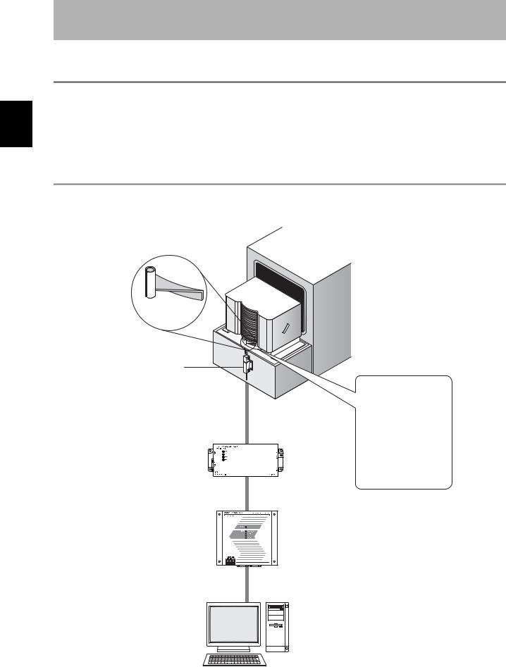
What Is a CIDRW System
The CIDRW system writes data to, and reads data from, the carrier IDs (ID Tags) mounted on the carriers (FOUP) in semiconductor manufacturing processes without contacting these ID Tags. CIDRW is the abbreviation of Carrier ID Reader/Writer and this abbreviation is used throughout this manual.
Reading and writing information such as models, process instructions, lots, and inspection results to and from ID Tags makes it possible to manage work instruction information from a host device.
Example: Management of information in semiconductor and wafer manufacturing processes
ID Tag (holder is separate)
CIDRW Head
Reading and writing information
• Model information
• Process instruction information
• Completion information
Amplifier Unit |
• Lot information |
• Inspection results Etc.
CIDRW Controller
Host
18 |
|
CIDRW System |
|
||
|
User’s Manual |
|
|
|
|
SECTION 1
Product Outline
Features
■CIDRW Systems That Conform to SEMI Standards (SEMI E99, E5, E4)
•V640-HAM11-V3
Host
SECS I/II
RS-232C
CIDRW System Conforming to SEMI Standards
CIDRW Controller
V700-L22
Amplifier Unit |
CIDRW Head |
V640-HAM11-V3 |
V640-HS61 |
RS-232C |
ID Tag
RI-TRP-DR2B(-30) RI-TRP-WR2B(-30) (Made by Texas Instruments)
The V640-HS61 CIDRW Head can be connected to V640-HAM11-V3 Amplifier Units to communicate with ID Tags.
• V640-HAM11-L
CIDRW System Conforming to SEMI Standards
|
CIDRW Controller |
Host |
V700-L22 |
Amplifier Unit |
CIDRW Head |
V640-HAM11-L |
V640-HS62 |
SECS I/II
RS-232C |
RS-232C |
ID Tag
RI-TRP-DR2B(-30) RI-TRP-WR2B(-30) (Made by Texas Instruments)
The V640-HS62 CIDRW Head can be connected to V640-HAM11-L Amplifier Units to communicate long-distance with ID Tags. The functions of the V640-HAM11-L Amplifier Unit are the same as the functions of the V640-HAM11-V3 Amplifier Unit.
List of Applicable Standards
•SEMI E99 THE CARRIER ID READER/WRITER FUNCTIONAL STANDARD
•SEMI E5 EQUIPMENT COMMUNICATION STANDARD 2 MESSAGE CONTENT (SECS II)
•SEMI E4 EQUIPMENT COMMUNICATION STANDARD 1 MESSAGE TRANSFER (SECS I)
SEMI is the acronym for Semiconductor Equipment and Materials International.
SECS is the acronym for SEMI Equipment Communications Standard.
The V640-HAM11-V3 or V640-HAM11-L will automatically detect the model and read/write data for RI-TRP- DR2B(-30) and RI-TRP--WR2B(-30) ID Tags manufacturer by Texas Instruments.
Features 1 SECTION
CIDRW System |
19 |
User’s Manual |
Configuration System 1 SECTION
SECTION 1
Product Outline
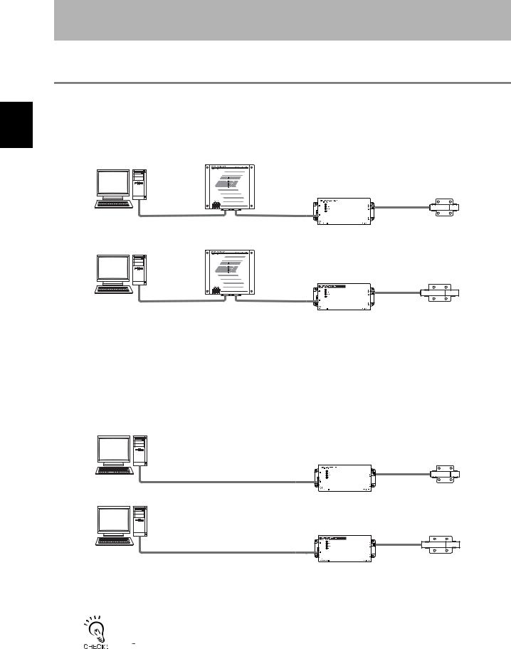
System Configuration
 When SECS Is Used
Communications with the host device is possible using the SECS protocol.
Host
RS-232C
SECS I/II
Host
RS-232C
SECS I/II
This is a host computer, equipment controller, etc.
CIDRW Controller
V700-L22
Amplifier Unit |
CIDRW Head |
|
V640-HAM11-V3 |
||
V640-HS61 |
||
|
RS-232C
CIDRW Controller
V700-L22
|
Amplifier Unit |
CIDRW Head |
|
V640-HAM11-L |
|
|
V640-HS62 |
|
|
|
|
RS-232C |
|
|
Multiple Amplifier Units |
The Amplifier Units con- |
The CIDRW Heads are the |
are controlled in |
trol the CIDRW Heads. |
antennas for reading the |
response to commands |
|
carrier IDs from the ID Tags |
(SECS) from the host |
|
and writing the carrier IDs. |
device. |
|
|
 When SECS Is Not Used
Communications with the host device follow the OMRON proprietary protocol.
The Amplifier Units are connected directly to the host device without using a CIDRW Controller.
Host
|
Amplifier Unit |
CIDRW Head |
|
V640-HAM11-V3 |
|
|
V640-HS61 |
|
RS-232C |
|
|
|
|
|
OMRON proprietary protocol |
|
|
Host |
|
|
|
Amplifier Unit |
CIDRW Head |
|
V640-HAM11-L |
|
|
V640-HS62 |
|
RS-232C |
|
|
|
|
|
OMRON proprietary protocol |
|
|
This is a host computer, |
The Amplifier Units con- |
The CIDRW Heads are the |
equipment controller, etc. |
trol the CIDRW Heads. |
antennas for reading the |
|
|
carrier IDs from the ID Tags |
|
|
and writing the carrier IDs. |
Refer to the following page for connection examples for more than one Amplifier Units or for connection examples for using the V700-L11 Link Unit.
 page 121
Using Link Units (V700-L11) to make connections makes it possible to remove and replace just the relevant Amplifier Unit while leaving the power to the CIDRW system on in the event of a failure or during maintenance.
20 |
|
CIDRW System |
|
||
|
User’s Manual |
|
|
|
|
SECTION 1
Product Outline
Component Names and Functions
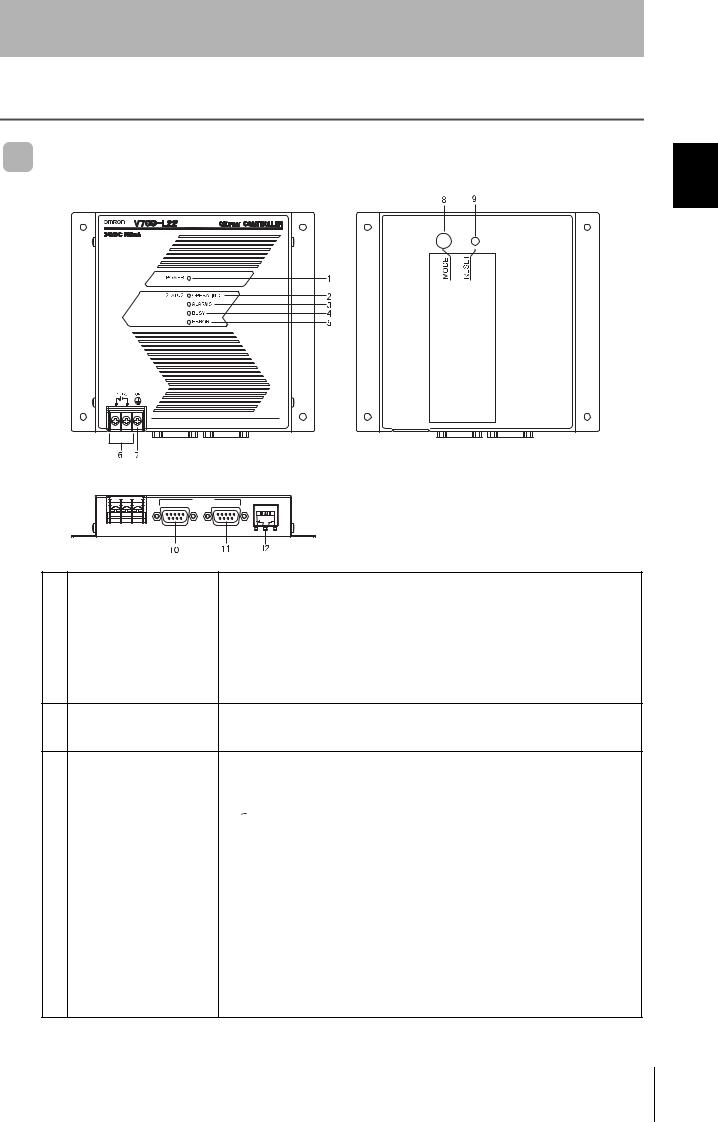
V700-L22 CIDRW Controller |
Functions and Names Component 1 SECTION
RS-232C |
ID |
MAINTENANNCE |
SECS |
|
No. |
Name |
Function |
1 |
Power indicator (green) |
An indicator that indicates whether the power is ON or OFF. Lit while the power is ON. |
|
|
|
2 |
OPERATING indicator (green) |
Lit while the CIDRW system status model is operating. |
|
|
|
3 |
ALARMS indicator (green) |
Lit when the status in "Alarm Status" of the CIDRW system is Alarm (1). |
|
|
|
4 |
BUSY indicator (green) |
Lit when the status in "Operational Status" of the CIDRW system is BUSY. |
|
|
|
5 |
ERROR indicator (red) |
When a processing error is detected (when SSACK is other than NO), this indicator is lit |
|
|
for 50 ms. |
624 VDC power supply termiConnect to the 24 VDC power supply. nals
(with cover)
7 |
Frame ground terminal |
The grounding wire is connected here. (Ground to 100 Ω or less) |
|
(with cover) |
|
|
|
|
8 |
MODE switch |
Used to select the mode of operation. |
 Refer to page 54.
0: Normal Operation mode. When mounting the Controller, set the switch to this position.
3:Setting mode, selected to set information such as the communications conditions. When the switch on the bottom face of the Controller cannot be accessed, the operation mode can be changed from the host device while the switch is left at the 0 setting.
|
|
1 to 2, 4 to 7: Setting prohibited |
|
|
|
9 |
RESET switch |
Restarts the CIDRW Controller. |
|
|
|
10 |
SECS port |
Port for connecting the host device. Conforms to SECS I/II. |
|
|
|
11 |
ID port |
An Amplifier Unit or Link Unit is connected here. |
|
|
|
12 |
Maintenance port (with cover) |
Not used. Do not remove the cover. |
CIDRW System |
21 |
User’s Manual |
SECTION 1
Product Outline
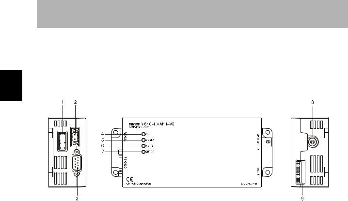
 V640-HAM11-V3 and V640-HAM11-L Amplifier Units
Functions and Names Component 1 SECTION
No. |
Name |
Function |
1 |
Dedicated power supply con- |
Connect to the 24 VDC power supply. |
|
nector |
|
|
|
|
2 |
RS-485 port |
When using multiple CIDRW Heads, connect this to the RS-485 port of another Amplifier |
|
|
Unit or to the multi-connection port of a Link Unit. |
|
|
|
3 |
RS-232C port |
Connected to a CIDRW Controller or a host device. |
|
|
Uses the OMRON proprietary communications protocol. |
|
|
|
4 |
RUN indicator (green) |
Turns ON when the Amplifier Unit is in normal operation. |
|
|
|
5 |
COMM indicator (yellow) |
Turns ON during communications with the host device or during communications with an |
|
|
ID Tag. |
|
|
|
6 |
NORM indicator (green) |
Turns ON when the communications finish with no error. |
|
|
|
7 |
ERROR indicator (red) |
Turns ON when an error occurs during communications with the host device, or during |
|
|
communications with an ID Tag. |
|
|
|
8 |
CIDRW Head connection port |
A CIDRW Head is connected here. |
|
|
|
9 |
Setting DIP switches |
Used to set the node number, the communications conditions, and the RS-485 terminal |
|
|
resistance. |
|
|
|
22 |
|
CIDRW System |
|
||
|
User’s Manual |
|
|
|
|

SECTION 1
Product Outline
■ Functions
• NOISE MEASUREMENT
The levels of noise in the vicinity of the CIDRW Head are measured and the noise level is expressed numerically in the range "00" to "99.
 Refer to page 100, page 152.
• Detecting for CIDRW Head status
You can confirm if the CIDRW Head is connected to the Amplifier Unit correctly.
 Refer to page 98.
• Test Mode
Test Mode can be used to check communications between the ID Tags and Amplifier Units without connecting a host device. Communications with ID Tags are automatically performed every second and the communications results are displayed on the OPERATING indicator.
 Refer to page 67.
Refer to V640-HAM11-V3 and V640-HAM11-L Amplifier Units for information on the OPERATING indicator for communications results.


 page 22
Always connect the CIDRW Head before operating the Amplifier Unit in Test Mode. If Test Mode is used without connecting a CIDRW Head, the ERROR indicator will light and Amplifier Unit operation will stop.
Commands from the host device are not accepted during operation in Test Mode. To end Test Mode, turn OFF the Test Mode pin on the DIP switch and restart the Amplifier Unit.
Functions and Names Component 1 SECTION
CIDRW System |
23 |
User’s Manual |
SECTION 1
Product Outline
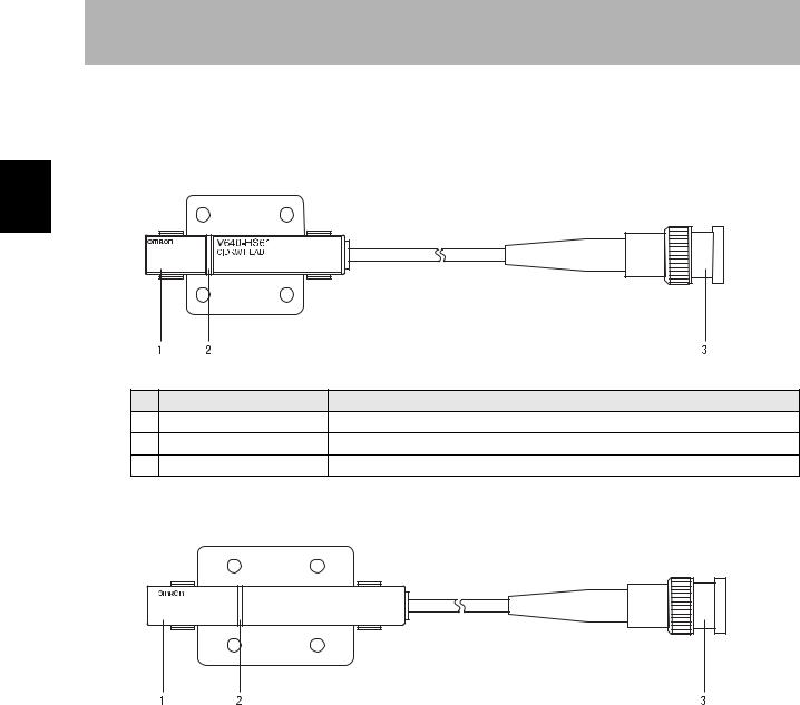
 V640-HS61 and V640-HS62 CIDRW Heads
■ V640-HS61
1 SECTION
and Names Component |
No. |
Name |
Function |
Functions |
1 |
Antenna |
Used to communicate with ID Tags. |
|
|||
|
2 |
Antenna center |
This is the center of the communications area. |
|
3 |
Connector |
Connect to an Amplifier Unit. |
■ V640-HS62
V640-HS62
CIDRW HEAD
MADE IN JAPAN
No. |
Name |
Function |
1 |
Antenna |
Used to communicate with ID Tags. |
|
|
|
2 |
Antenna center |
This is the center of the communications area. |
|
|
|
3 |
Connector |
Connect to an Amplifier Unit. |
|
|
|
24 |
|
CIDRW System |
|
||
|
User’s Manual |
|
|
|
|

|
|
|
|
|
|
|
|
|
|
|
|
|
|
|
|
|
|
|
|
|
|
|
|
|
|
|
|
|
|
|
|
|
|
SECTION 1 |
|
|
|
|
|
|
|
|
|
|
|
|
|
|
|
|
|
|
|
|
|
|
|
|
|
|
|
|
|
|
|
|
|
|
|
|
Product Outline |
|
|
|
|
|
|
|
|
|
|
|
|
|
|
|
|
|
|
|
|
|
|
|
|
|
|
|
|
|
|
|
|
|
|
|
|
|
|
|
|
V700-L11 Link Unit |
|
|
|
|
|
|
|
|
|
|
|
|
|
|
|
|
|
|
|
|
|
|
|
|
|
|
|
|
|||||||
|
|
|
|
|
|
|
|
|
|
|
|
|
|
|
|
|
|
|
|
|
|
|
|
|
|
|
|
|
|
|
|
|
|
|
|
|
|
|
|
|
|
|
|
|
|
|
|
|
|
|
|
|
|
|
|
|
|
|
|
|
|
|
|
|
|
|
|
|
|
|
|
|
1 SECTION |
|
|
|
|
|
|
|
|
|
|
|
|
|
|
|
|
|
|
|
|
|
|
|
|
|
|
|
|
|
|
|
|
|
|
|
|
|
|
|
|
|
|
|
|
|
|
|
|
|
|
|
|
|
|
|
|
|
|
|
|
|
|
|
|
|
|
|
|
|
|
|
|
|
|
|
|
|
|
|
|
|
|
|
|
|
|
|
|
|
|
|
|
|
|
|
|
|
|
|
|
|
|
|
|
|
|
|
|
|
|
|
|
|
|
|
|
|
|
|
|
|
|
|
|
|
|
|
|
|
|
|
|
|
|
|
|
|
|
|
|
|
|
|
|
|
|
|
Functions and Names Component |
|
|
|
|
|
|
|
|
|
|
|
|
|
|
|
|
|
|
|
|
|
|
|
|
|
|
|
|
|
|
|
|
|
|
|
|
|
|
|
|
|
|
|
|
|
|
|
|
|
|
|
|
|
|
|
|
|
|
|
|
|
|
|
|
|
|
|
|
|
|
|
|
|
|
|
|
|
|
|
|
|
|
|
|
|
|
|
|
|
|
|
|
|
|
|
|
|
|
|
|
|
|
|
|
|
|
|
|
|
|
|
|
|
|
|
|
|
|
|
|
|
|
|
|
|
|
|
|
|
|
|
|
|
|
|
|
|
|
|
|
|
|
|
|
|
|
|
|
|
|
|
|
|
|
|
|
|
|
|
|
|
|
|
|
|
|
|
|
|
|
|
|
|
|
|
|
|
|
|
|
|
|
|
|
|
|
|
|
|
|
|
|
|
|
|
|
|
|
|
|
|
|
|
|
|
|
|
|
|
|
|
|
|
|
|
|
|
|
|
|
|
|
|
|
|
|
|
|
|
|
|
|
|
|
|
|
|
|
|
|
|
|
|
|
|
|
|
|
|
|
|
|
|
|
|
|
|
|
|
|
|
|
|
|
|
|
|
|
|
|
|
|
|
|
|
|
|
|
|
|
|
|
|
|
|
|
|
|
|
|
|
|
|
|
|
|
|
|
|
|
|
|
|
|
|
|
|
|
|
|
|
|
|
|
|
|
|
|
|
|
|
|
|
|
|
|
|
|
|
|
|
|
|
|
|
|
|
|
|
|
|
|
|
|
|
|
|
|
|
|
|
|
|
|
|
|
|
|
|
|
|
|
|
|
|
|
|
|
|
|
|
|
|
|
|
|
|
|
|
|
|
|
|
|
|
|
|
|
|
|
|
|
|
|
|
|
|
|
|
|
|
|
|
|
|
|
|
|
|
|
|
|
|
|
|
|
|
|
|
|
|
|
|
|
|
|
|
|
|
|
|
|
|
|
|
|
|
|
|
|
|
|
|
|
|
|
|
|
|
|
|
|
|
|
|
|
|
|
|
|
|
|
|
|
|
|
|
|
|
|
|
|
|
|
|
|
|
|
|
|
|
|
|
|
|
|
|
|
|
|
|
|
|
|
|
|
|
|
|
|
|
|
|
|
|
|
|
|
|
|
|
|
|
|
|
|
|
|
|
|
|
|
|
|
|
|
|
|
|
|
|
|
|
|
|
|
|
|
|
|
|
|
|
|
|
|
|
|
|
|
|
|
|
|
|
|
|
|
|
|
|
|
|
|
|
|
|
|
|
|
|
|
|
|
|
|
|
|
|
|
|
|
|
|
|
|
|
|
|
|
|
|
|
|
|
|
|
|
|
|
|
|
|
|
|
|
|
|
|
|
|
|
|
|
|
|
|
|
|
|
|
|
|
|
|
|
|
|
|
|
|
|
|
|
|
|
|
|
|
|
|
|
|
|
|
|
|
|
|
|
|
|
|
|
|
|
|
|
|
|
|
|
|
|
|
|
|
No. |
Name |
|
|
|
|
|
|
|
|
|
|
|
|
|
|
|
|
|
|
|
|
|
|
Function |
|
||||||||||
|
|
|
|
|
|
|
|
|
|
|
|
|
|
|
|
|
|
|
|
|
|
|
|
|
||||||||||||
|
1 |
Multi-connection port |
|
This is the port that connects to the Amplifier Units when multiple CIDRW Heads are |
|
|
||||||||||||||||||||||||||||||
|
|
(RS-485) |
|
connected to a CIDRW Controller. The GR (frame ground) terminal is also at this port. |
|
|
||||||||||||||||||||||||||||||
|
|
|
|
|
|
|
|
|
|
|
|
|
|
|
|
|
|
|
|
|
|
|
|
|
|
|
|
|
|
|
|
|
|
|
|
|
|
2 |
RUN indicator (green) |
|
Turns ON while the Link Unit is in normal operation. |
|
|
||||||||||||||||||||||||||||||
|
|
|
|
|
|
|
|
|
|
|
|
|
|
|
|
|
|
|
|
|
|
|
|
|
|
|
|
|
|
|
|
|
|
|
|
|
|
3 |
ID indicator (green) |
|
Not used |
|
|
||||||||||||||||||||||||||||||
|
|
|
|
|
|
|
|
|
|
|
|
|
|
|
|
|
|
|
|
|
|
|
|
|
|
|
|
|
|
|
|
|
|
|
|
|
|
4 |
COMM indicator (green) |
|
Turns ON during data communications with the host device. |
|
|
||||||||||||||||||||||||||||||
|
|
|
|
|
|
|
|
|
|
|
|
|
|
|
|
|
|
|
|
|
|
|
|
|
|
|
|
|
|
|
|
|
|
|
|
|
|
5 |
ERR indicator (red) |
|
Turns ON when an error occurs during data communications with the host device or |
|
|
||||||||||||||||||||||||||||||
|
|
|
|
|
|
|
|
|
Head. |
|
|
|||||||||||||||||||||||||
|
|
|
|
|
|
|
|
|
|
|
|
|
|
|
|
|
|
|
|
|
|
|
|
|
|
|
|
|
|
|
|
|
|
|
|
|
|
6 |
Host device connection port |
|
This is a port for connecting to the CIDRW Controller via an RS-232C interface. A dust |
|
|
||||||||||||||||||||||||||||||
|
|
(RS-232C) |
|
cover is fitted on shipment from the factory. Remove this cover before using the port. |
|
|
||||||||||||||||||||||||||||||
|
|
|
|
|
|
|
|
|
|
|
|
|
|
|
|
|
|
|
|
|
|
|
|
|
|
|
|
|
|
|
|
|
|
|
|
|
|
7 |
ID connection port |
|
Not used |
|
|
||||||||||||||||||||||||||||||
|
|
|
|
|
|
|
|
|
|
|
|
|
|
|
|
|
|
|
|
|
|
|
|
|
|
|
|
|
|
|
|
|
|
|
|
|
|
8 |
24 V power supply terminals |
|
Connect to the 24 VDC power supply. |
|
|
||||||||||||||||||||||||||||||
|
|
(inside the cover) |
|
|
|
|
|
|
|
|
|
|
|
|
|
|
|
|
|
|
|
|
|
|
|
|
|
|
|
|
|
|||||
|
|
|
|
|
|
|
|
|
|
|
|
|
|
|
|
|
|
|
|
|
|
|
|
|
|
|
|
|
|
|
|
|
|
|
|
|
|
9 |
Setting DIP switches |
|
Used to set the equipment number, the communications conditions, and the RS-485 ter- |
|
|
||||||||||||||||||||||||||||||
|
|
(inside the cover) |
|
minal resistance. |
|
|
||||||||||||||||||||||||||||||
|
|
|
|
|
|
|
|
|
|
|
|
|
|
|
|
|
|
|
|
|
|
|
|
|
|
|
|
|
|
|
|
|
|
|
|
|
CIDRW System |
25 |
User’s Manual |
Started Getting for Flowchart 1 SECTION
SECTION 1
Product Outline
Flowchart for Getting Started
 When SECS Is Used
Connectionsand |
|
|
|
Installation |
|
||
|
|
|
|
|
|
Refer to page 32. |
|
Installation |
|
|
|
|
|
|
|
Connection and Wiring |
|
||
|
|
|
|
|
|
Refer to page 37. |
|
|
|
|
|
|
|
|
|
Communicationsfor |
|
|
Setting the Communications Conditions for the CIDRW Controller |
||
|
||
|
Refer to page 54. |
|
|
|
|
|
|
|
Preparation |
Setting the Communications Conditions for Amplifier Units |
|
Refer to page 67. |
||
|
||
|
|
Setting the Communications Conditions for Link Units
 Refer to page 69.
Operation |
|
|
Test for Communications with the Host Device |
||
|
||
Trial |
Refer to page 70. |
|
|
||
|
ID Tag <-> CIDRW System Communications Test
Refer to page 72.
Check the Surrounding Environment
 Refer to page 34.
26 |
|
CIDRW System |
|
||
|
User’s Manual |
|
|
|
|
Communications |
|
|
|
When SECS Is Used |
|||
|
|
||
|
|
Refer to page 76. |
|
|
|
|
|
|
|
|
When you Encounter a Problem...
When SECS Is Used
Refer to page 102. List of Error Messages
Refer to page 102. Controller Indicators
Refer to page 103. Operation Check Flowchart
SECTION 1
Product Outline
Started Getting for Flowchart 1 SECTION
CIDRW System |
27 |
User’s Manual |

Started Getting for Flowchart 1 SECTION
SECTION 1
Product Outline
 When SECS Is Not Used
Connectionsand |
|
|
|
Installation |
|
||
|
|
|
|
|
|
Refer to page 32. |
|
Installation |
|
|
|
|
|
|
|
Connection and Wiring |
|
||
|
|
|
|
|
|
Refer to page 37. |
|
|
|
|
|
|
|
|
|
Communicationsfor |
|
|
|
Setting the Communications Conditions for Amplifier Units |
|
||
|
|
|
|
|
|
Refer to page 67. |
|
Preparation |
|
|
|
|
|
||
|
Setting the Communications Conditions for Link Units |
|
|
|
Refer to page 69. |
|
|
|
|
|
|
|
|
|
|
|
|
|
|
Test for Communications with the Host Device
Refer to page 70.
Operation |
|
|
Communications Test between ID Tags and CIDRW System |
||
|
||
Trial |
Refer to page 72. |
|
|
||
|
|
|
|
Check the Surrounding Environment |
|
|
Refer to page 34. |
|
|
|
28 |
|
CIDRW System |
|
||
|
User’s Manual |
|
|
|
|
Loading...