

Omron NCF71, MECHATROLINK-II CS1W-NC271, MECHATROLINK-II CS1W-NC471, MECHATROLINK-II CS1W-NCF71 System Configuration Manual
Page 1

CS1W-NC271/471/F71 - MECHATROLINK-II
Position control unit
Multi-axis point-to-point positioning controller
over MECHATROLINK-II motion bus
• Position control units with 2, 4 or 16 axes.
• High-speed bus MECHATROLINK-II is specially
designed for motion control.
• Supports position, speed and torque control.
• Programming languages: ladder, function blocks.
Supports PLC Open Function Blocks.
• Smart active parts for OMRON HMIs terminals reduce
engineering time.
• Access to the complete system from one point. Network setup, servo drives configuring and monitoring,
and PLC programming.
System configuration
Motion controllers
Accurax G5 series
Servo motors
CS1 series
Position control unit
CS1W-NC_71
Accurax G5 series
Servo drive
MECHATROLINK-II
Input
Fast registration
inputs, home and
limits switches...
Personal computer
software: CX-One
2...16 axes max.
G- Series
Servo drive
AC SERVO DRIVER
ADR
1
1
0
0
9
2
2
8
3
3
7
4
6
5
X10
X1
COM
SP
IM
G
Terminator
G-Series
Servo motors
39Position control unit
Page 2
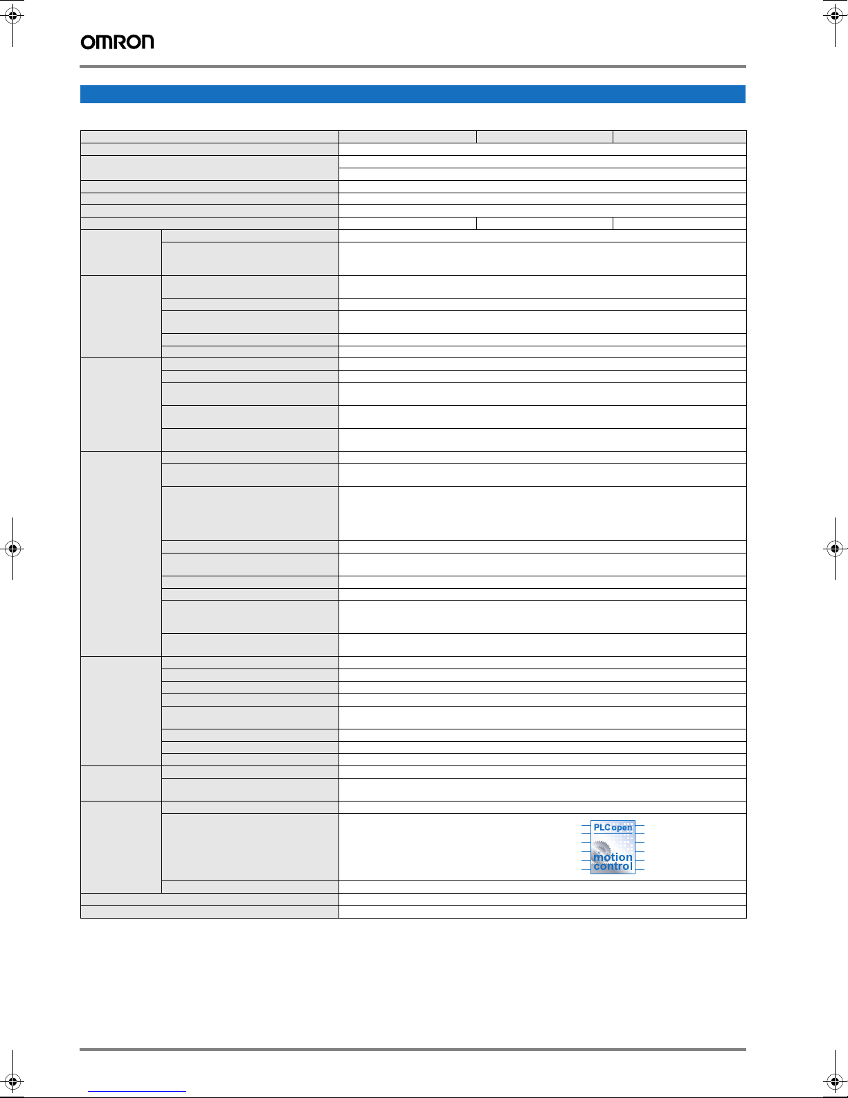
Specifications
Position control unit
Model CS1W-NC271 CS1W-NC471 CS1W-NCF71
Classification CS-series CPU bus unit
Applicable PLCs CS-series
Possible unit number settings 0 to F
Control method MECHATROLINK-II (position, speed and torque control )
Controlled devices Accurax G5 and G-Series servo drives with MECHATROLINK-II built-in
Controlled axes 2 maximum 4 maximum 16 maximum
I/O allocations Common operating memory area Words allocated in CPU bus unit area: 25 words (15 output words, 10 input words)
Control units Position command unit Command unit: Depends on the electronic gear setting in the servo parameters.
Control command
range
Control functions Servo lock/unlock Locks and unlocks the servo driver.
Auxiliary functions Acceleration/deceleration curves Sets either a trapezoidal (linear) curve, an exponential curve, or an S-curve (moving average).
External I/O Position control unit One MECHATROLINK-II interface port
Programming
methods
Axis operating memory area Allocated in one of the following areas (user-specified):
Speed command unit for position control Command units/s
Acceleration/deceleration speeds for
position control
Speed command unit for speed control 0.001% of the motor's maximum speed
Torque command unit for torque control 0.001% of the motor's maximum torque
Position command range -2,147,483,648 to 2,147,483,647 (command units)
Speed command range for position control 0 to 2,147,483,647 (command units/s)
Acceleration/deceleration speeds for
position control
Speed command range for speed control -199.999% to 199.999%
Torque command range for torque control -199.999% to 199.999%
Position control Positions to an absolute position or relative p ositi on acco rding to the specified target posit ion and tar-
Origin determination • Origin search: Establishes the origin using the specified search method.
Jogging Outputs a fixed speed in the CW or CCW direction.
Interrupt feeding Performs positioning by moving the axis a fixed amount when an external interrupt input is received
Speed control Performs speed control by sending a command to the servo drive speed loop.
Torque control Performs torque control by sending a command to the servo drive current loop.
Stop functions • Deceleration stop: Decelerates the moving axis to a stop.
Linear interpolation Up to 8 axes can be interpolated by using two interpolators (4 axes per interpolator)
Torque limit Restricts the torque upper limit during position control.
Override Multiplies the axis command speed by a specified ratio. Override : 0.01% to 327.67%
Servo parameter transfer Reads and writes the servo drive parameters from the ladder program in the CPU unit.
Monitoring function Monitors the control status of the servo drive's command coordinate positions, feedback position,
Software limits Limits software operation for controlling positioning.
Backlash compensation Compensates for the amount of play in the mechanical system according to a set value.
Deviation counter reset The position deviation in the servo drive’s deviation counter can be reset to 0 (unit version 1.3 or later).
Servo driver I/O CW/CCW limit inputs, origin proximity inputs, external interrupt inputs 1 to 3
Standard ladder Directly over NCF unit memory area
Function blocks Using standard PLC open function blocks
CS-series (V. 3.0 or later if use of function blocks is needed)
CIO, Work, Auxiliary, Holding, DM, or EM Area.
Number of words allocated: 50 words (25 output words, 25 input words) × highest axis No. used
Default setting: Pulses
10,000 command units/s
1 to 65,535 (10,000 command units/s2)
The upper limit is restricted by the maximum speed of the servo motor.
The upper limit is restricted by the maximum torque of the servo motor.
get speed specified from the ladder program.
• Present position preset: Changes the present position to a specified position to establish the origin.
• Origin return: Returns the axis from any position to the established origin.
Absolute encoder origin: Establishes the origin using a Servomotor that has an absolute encoder,
without having to use an origin search.
while the axis is moving.
• Emergency stop: Positions the moving axis for the number of pulses remaining in the deviation
counter and then stops the axis.
Available in unit version 1.1 or higher
current speed, torque, etc.
(can be used as external origin inputs)
2
Internal current consumption 360 mA or less at 5 VDC
Weight 188 g
Smart active parts Use of OMRON HMIs smart active parts optimizes CPU usage and engineering time
40 Motion controllers
Page 3

Nomenclature
CS1W-NC271/471/F71 - Position control unit
Dimensions
CS1W-NC271/471/F71 - Position control unit
34.5
NCF71
RUN
ERH
ERC
ERM
MLK
UNIT
No.
LED indicators
MLK - MECHATROLINK-II network status
RUN - Controller in RUN
ERC - Position control unit error
ERH - PLC CPU unit error
ERM - MECHATROLINK-II slave unit error
UNIT No. setting switch
MECHATROLINK-II communications connectors:
Connects to MECHATROLINK-II nodes
100.5 6.2
Motion controllers
130
MLK
Position control unit 41
Page 4

Ordering information
Position controller unit
Name Model
MECHATROLINK-II position controller unit - 16 axes CS1W-NCF71
MECHATROLINK-II position controller unit - 4 axes CS1W-NC471
MECHATROLINK-II position controller unit - 2 axes CS1W-NC271
MECHATROLINK-II related devices
Servo system
Name Model
Accurax G5 servo drive ML-II built-in R88D-KN@@@-ML2
G-Series servo drive ML-II built-in R88D-GN@@H-ML2
Note: Refer to servo systems section for detailed specs and ordering information
MECHATROLINK-II cables
Name Remarks Model
MECHATROLINK-II
terminator
MECHATROLINK-II
cables
Computer software
Specifications Model
CX-One version 1.1 or higher CX-One
Terminating resistor JEPMC-W6022
0.5 meter JEPMC-W6003-A5
1 meter JEPMC-W6003-01
3 meters JEPMC-W6003-03
5 meters JEPMC-W6003-05
10 meters JEPMC-W6003-10
20 meters JEPMC-W6003-20
30 meters JEPMC-W6003-30
ALL DIMENSIONS SHOWN ARE IN MILLIMETERS.
To convert millimeters into inches, multiply by 0.03937. To convert grams into ounces, multiply by 0.03527.
Cat. No. I10E-EN-02A
In the interest of product improvement, specifications are subject to change without notice.
42 Motion controllers
 Loading...