

Page 1
MP2100 - MECHATROLINK-II
PC motion controller
PC based solution for advanced
motion control
• Up to 32 axes controlled with minimum wiring
• Motion APIs are available for customised control
aplications. Motion commands can be input from either
the PC application or the MP2100 program
• Self configuration of nodes for an easy setup
• Supports position, speed and torque control
• Electronic CAM profiles and axes synchronization
• The high-speed bus MECHATROLINK-II is specially
designed for motion control
• Support for I/Os locally and over the network
• Access to the complete system from one point
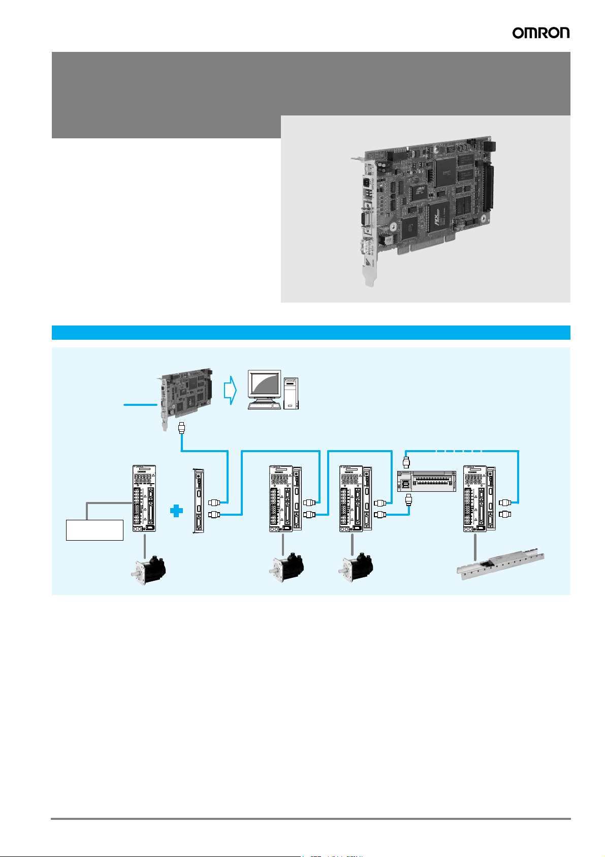
System configuration
Motion controller MP2100
(The MP2100M can
handle up to 2
Mechatrolink-II network)
Local I/Os
Sigma-II series
Servo Drive
Input
Limit switches
contact sensors
SGDH-
Ver.
CHARGE POWER
CN3
CN1
CN2
SERVOPACK
200V
NS115
S
W
1
A
R
S
W
2
C
N
6
A
C
N
6
B
C
N
4
JUSP-NS115
Mechatrolink-II
unit
Sigma-II series
Servo Motor
MECHATROLINK-II
SERVOPACK
NS115
SGDH-
S
200V
Ver.
W
1
A
R
S
W
2
CHARGE POWER
CN3
C
N
6
A
CN1
C
N
6
B
C
N
4
CN2
Personal computer
Software: MPE720 tool
Motion API
SERVOPACK
NS115
SGDH-
S
200V
Ver.
W
1
A
R
S
W
2
CHARGE POWER
CN3
C
N
6
A
CN1
C
N
6
B
C
N
4
CN2
21 nodes max.
16 servo axes max. + I/O stations
Totel length: 50 m
I/O module
RUNTX 1 2 3 4 5 6 7 8 120DDI 343 30
C
N
1
C
N
2
SERVOPACK
SGDH-
Ver.
CHARGE POWER
CN3
CN1
CN2
NS115
S
200V
W
1
A
R
S
W
2
C
N
6
A
C
N
6
B
C
N
4
Terminator
Sigma-II series
Linear Motor
77PC motion controller
Page 2
Specifications
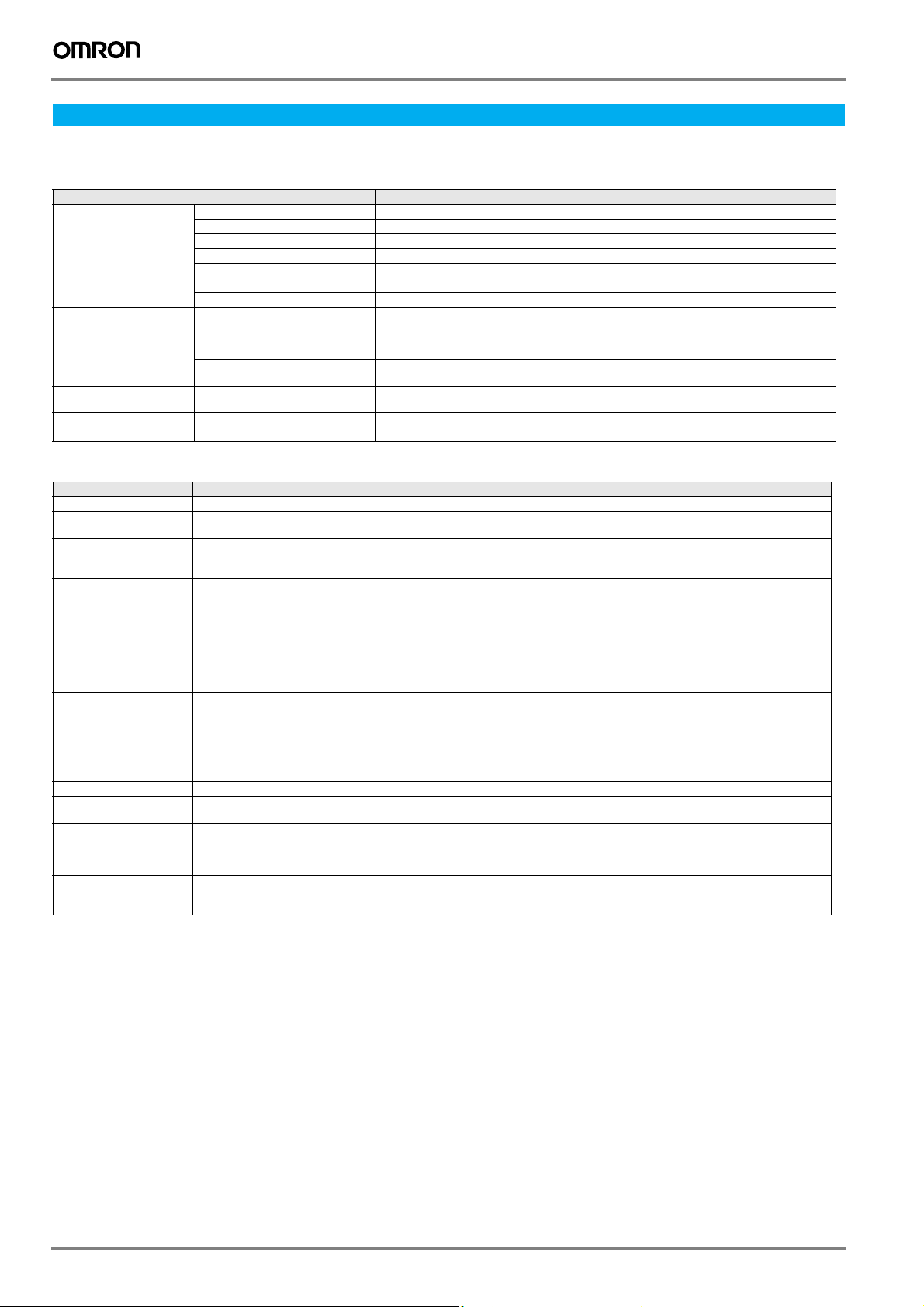
General specifications
Hardware specifications
Items Specifications
Environmental
conditions
Mechanical operating
conditions
Electrical operating
conditions
Installation
requirements
Sequential function specifications
Items Specifications
Control method Sequence: High-speed and low-speed scan methods
Programming language Ladder diagram: Relay circuit
Scanning Two scan levels: High-speed scan and low-speed scan
User drawings, functions
and motion programs
Data memory Common data (M) registers:
Trace memory Data trace: 128 Kwords (32 Kwords / 4 groups), 16 points defined
Memory backup Program memory: Flash memory: 8 MBytes (User area: 5.5 MBytes) definition files, ladder programs, motion programs, etc.
Data types Bit (relay): ON/OFF
Register designation
method
Ambient operating temperature 0 to 55 °C
Ambient storage temperature -25 to 85 °C
Ambient operating humidity 30% to 95% (with no condensation)
Ambient storage humidity 5% to 95% (with no condensation)
Pollution level Pollution level 1 (conforming to JIS B 3501)
Corrosive gas There must be no combustible or corrosive gas.
Operating altitude 2,000 m above sea level or lower
Vibration resistance Conforming to JIS B 3502:
Shock resistance Conforming to JIS B 3502:
Noise resistance Conforming to EN 61000-6-2, EN 55011 (Group 1, Class A)
Ground Ground to 100 Ω max.
Cooling method Natural cooling
Text-type language: Numeric operations, logic operations, etc.
High-speed scan time setting: 1 to 32 ms (Integral multiple of MECHATROLINK communication cycle)
Low-speed scan time setting: 2 to 300 ms (Integral multiple of MECHATROLINK communication cycle)
Startup drawings (DWG.A):
Interrupt processing drawings (DWG.I):
High-speed scan process drawings (DWG.H):
Low-speed scan process drawings (DWG.L):
Number of steps:
User functions:
Motion programs:
Revision history of drawings and motion programs
Security function for drawings and motion programs
System (S) registers:
Drawing local (D) registers:
Drawing constant (#) registers:
Input (I) registers:
Output (O) registers:
Constant (C) registers:
Data memory: Battery backup: 256 Kbytes, M registers, S registers, alarm history, trace data
Integer: -32768 to +32767
Double-length integer: -2147483648 to +2147483647
Real number: ± (1.175E-38 to 3.402E+38)
Register number: Direct designation of register number
Symbolic designation: Up to 8 alphanumeric characters (up to 200 symbols per drawing)
With automatic number or symbol assignment
10 to 57 Hz with single-amplitude of 0.075 mm
57 to 150 Hz with fixed acceleration of 1 G
10 sweeps each in X, Y, and Z directions (sweep time: 1 octave/min)
2
Peak acceleration of 147 m/s
(15 G) twice for 11 ms each in the X, Y, and Z directions
64 drawings max. up to three hierarchical drawing levels
64 drawings max. up to three hierarchical drawing levels
200 drawings max. up to three hierarchical drawing levels
500 drawings max. up to three hierarchical drawing levels
Up to 1,000 steps per drawing
Up to 500 functions
Up to 256
64 Kwords
8 Kwords
Up to 16 Kwords per drawing
Up to 16 Kwords per drawing
5 Kwords (including internal input registers)
5 Kwords (including internal output registers)
16 Kwords
78 Motion controllers
Page 3
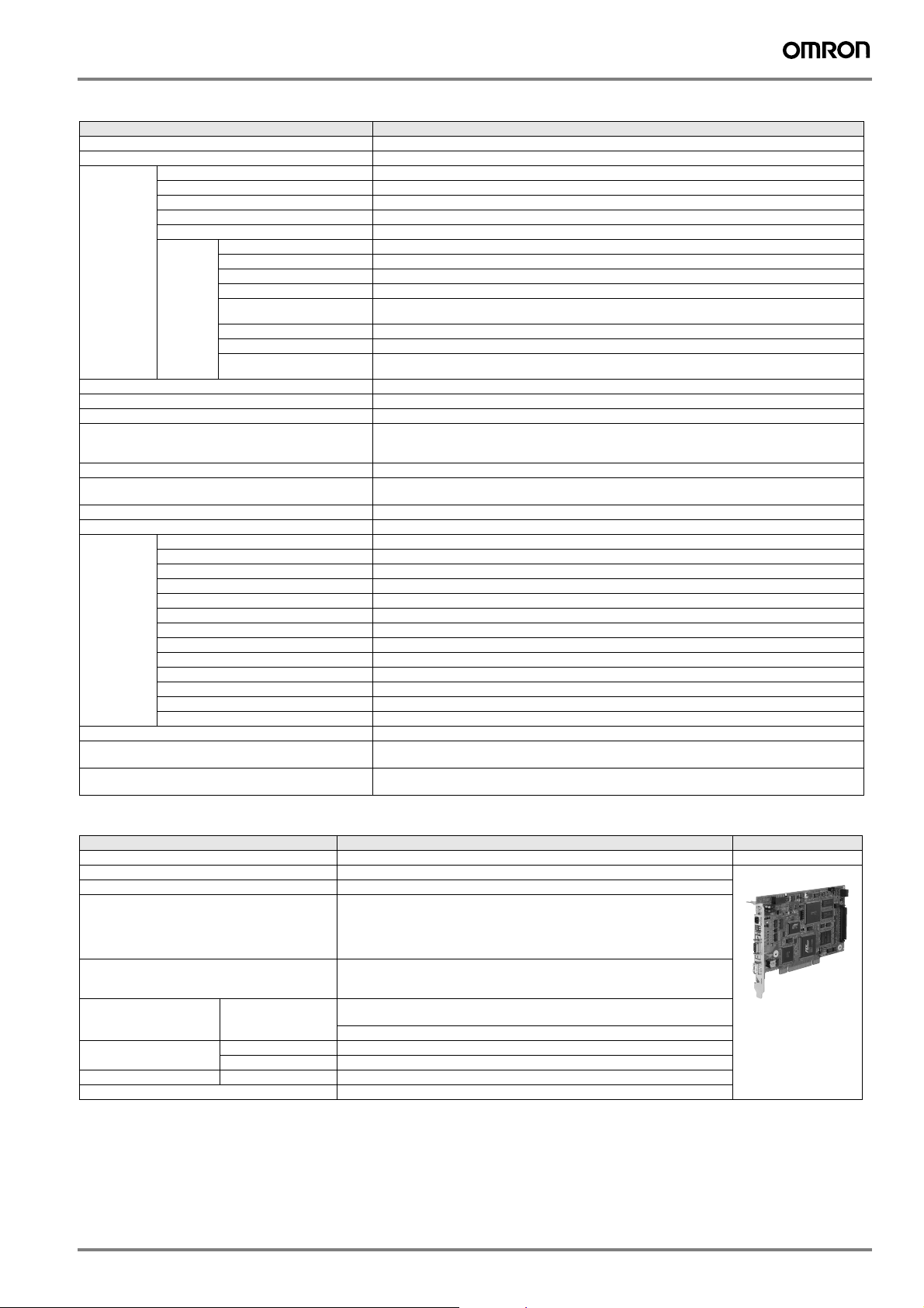
Motion control function specifications
Item Specifications
Interface MECHATROLINK-I, MECHATROLINK-II
Number of controlled axes/module Up to 16 axes
Control
specifications
Reference unit mm, inch, deg, or pulse
Reference unit minimum setting 1, 0.1, 0.01, 0.001, 0.0001, 0.00001
Maximum programmable value -2147483648 to +2147483647 (signed 32-bit value)
Speed reference unit Reference unit/s designation: mm/s, inch/s, deg/s, pulse/s
Acceleration/deceleration type Linear, asymmetric, S-curve, exponent
Acceleration/deceleration reference unit Reference unit/s
Override function Positioning: 0.01% to 327.67% by axis
Coordinate system Rectangular coordinates
Zero point re-
turn
Applicable servo drives SGDH-@@@E-OY + NS115
Applicable frequency inverters Varispeed V7, F7, G7 with MECHATROLINK-II Interface
Encoders Incremental encoder
PTP control Linear, rotary, and infinite-length
Interpolation Up to 16 linear axes, 2 circular axes, and 3 helical axes
Speed reference output Yes
Torque reference output Yes
Phase control Yes
Position
control
DEC1+ phase-C pulse Yes
ZERO signal Yes
DEC1+ ZERO signal Yes
Phase-C pulse Yes
Only phase-C pulse Yes
POT and
POT Yes
Home limit switch and
HOME Yes
NOT and
NOT Yes
INPUT and
INPUT Yes
Positioning Yes
External positioning Yes
Zero point return Yes
Interpolation Yes
Interpolation with position
detection function
JOG operation Yes
STEP operation Yes
Parameter changes during
motion command execution
phase-C pulse
phase-C pulse
phase-C pulse
phase-C pulse
.
Yes
Yes
Reference unit/min. designation: mm/min, inch/ min, deg/min, pulse/min
Percentage designation: Percentage of rated speed
2
Acceleration/deceleration time constant: Time from 0 to rated speed (ms)
(for inverter’s version supported contact your OMRON sales office)
Yaskawa absolute encoder
designation: mm/s2, inch/s2, deg/s2, pulse/s
Yes
Yes
Yes
Yes
2
MP2100, MP2100M boards
Items Specifications Appearance
Model JAPMC-MC2100, JAPMC-MC2140
Power supply Input supply voltage: 5 VDC±5%
Dimensions 106.68x174.63 mm half the size of a standard PCI
Motion network MECHATROLINK-II: One channel with MP2100, two channels with MP2100M
I/O signals Digital input: 5 points (one point can be used for interrupts),
Electrical
operating
conditions
Mechanical operating
conditions
Installation requirements Ground Follows the personal computer’s requirements
Environmental conditions Same as the general specifications
Noise
resistance
Vibration resistance Not specified
Shock resistance Not specified
Twenty-one stations, including servo drives, inverters and I/O equipment, can be
connected. (16 axes for servo drives and inverters)
Transmission speed: 10Mbps (MECHATROLINK-II)
Transmission distance: See “MECHATROLINK-II repeater”
Digital output: 4 points, 24 VDC, 100 mA, open collector, and sink mode output
Radiation noise (FT noise): 1 kV or more for 1 min.
Static noise (contact discharging method): 6 kV or more for 10 times
Other noise: Not specified
24 VDC, 4 mA, and source mode or sink mode input
PC motion controller 79
Page 4
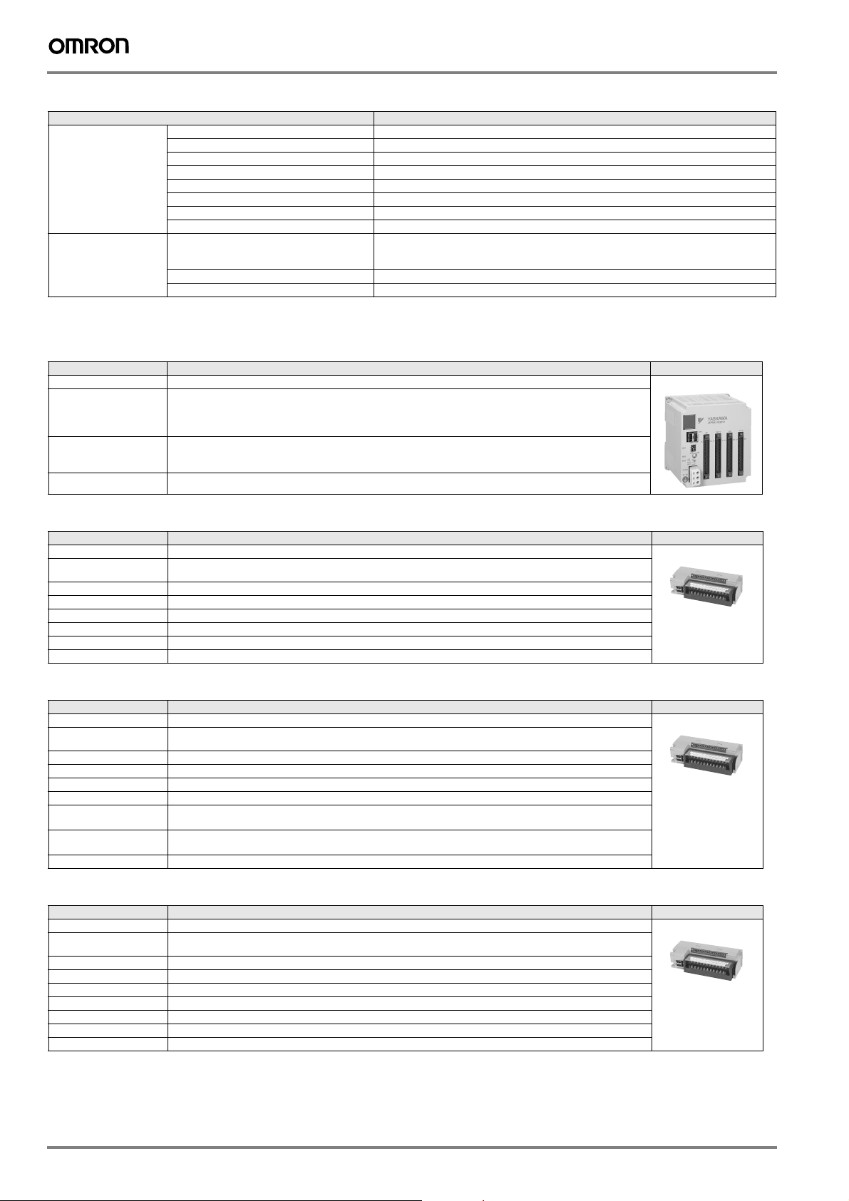
Host computer specifications
Items Specifications
Hardware Model PC/AT compatible
Software OS Windows NT 4.0 Workstation SP5 or later
1. These specifications are applicable if using one MP2100s board. If using two or more boards in the same host personal computer, expanasion slots, interrupts and I/O memory resources needs to be increased per each board.
MECHATROLINK-II, 64 point I/O module (IO2310)
Items Specifications Appearance
Model JEPMC-IO2310
I/O signals Input: 64 points, 24 VDC, 5 mA, sink/source mode input
Module power
supply
Weight 590 g
CPU Pentium 200 MHz or more (Pentium 400 MHz or more recommended)
Memory capacity 64 MB or more
Hard disk drive capacity Free space 500 MB or more
Display resolution 800x600 or more (1024x768 recommended)
Expansion slot
Interrupts
I/O memory
Web browser Microsoft IE 5.5 SP2 or later
Language Microsoft Visual C/C++ 6.0 SP5 or later
Output: 64 points, 24 VDC, 50 mA when all points ON,
Signal connection method: Connector (FCN360 series)
24 VDC (20.4 V to 28.8 V)
Rated current: 0.5 A
Inrush current: 1 A
1
1
1
(The max. rating is 100 mA per point) sink mode output (NPN)
Half the size of a standard PCI slot
First-level use (IRQ sharing is possible)
32 kB shared memory used
Windows 2000 Professional SP1 or later
Windows XP
MECHATROLINK-II, counter module (PL2900)
Items Specifications Appearance
Model JEPMC-PL2900
Number of input
channels
Functions Pulse counter, notch output, registration input
Pulse input method Sign (1/2 multipliers), A/B (1/2/4 multipliers), UP/DOWN (1/2 multipliers)
Max. counter speed 1200 kpps (4 multipliers)
Pulse input voltage 3/5/12/24 VDC
External power supply For input signal: 24 VDC, for dividing load: 24 VDC, for module: 24 VDC (20.4 V to 26.4 V), 120 mA or less
Weight 300 g
2
MECHATROLINK-II, pulse output module (PL2910)
Items Specifications Appearance
Model JEPMC-PL2910
Number of output
channels
Functions Pulse positioning, JOG run, zero-point return
Pulse output method CW, CCW pulse, sign
Max. output speed 500 kpps
Pulse output voltage 5VDC
Pulse interface circuit Open collector output
External control signal Digital input: 8 points/module, 5 VDC x 4 points, 24 VDC x 4 points
Weight 300 g
2
5 VDC, 10 mA/circuit
Digital output: 6 points/module, 5 VDC x 4 points, 24 VDC x 2 points
MECHATROLINK-II, analog input module (AN2900)
Items Specifications Appearance
Model JEPMC-AN2900
Number of input
channels
Input voltage range -10 V to +10 V
Input impedance 1MΩ min.
Data format Binary, -32000 to +32000
Input delay time 4ms max.
Error ± 0.5% F.S. (at 25 °C), ± 1.0% F.S. (at 0 °C to 60 °C)
External power supply 24 VDC (20.4 VDC to 26.4 VDC), 120 mA max.
Weight 300 g
4
80 Motion controllers
Page 5
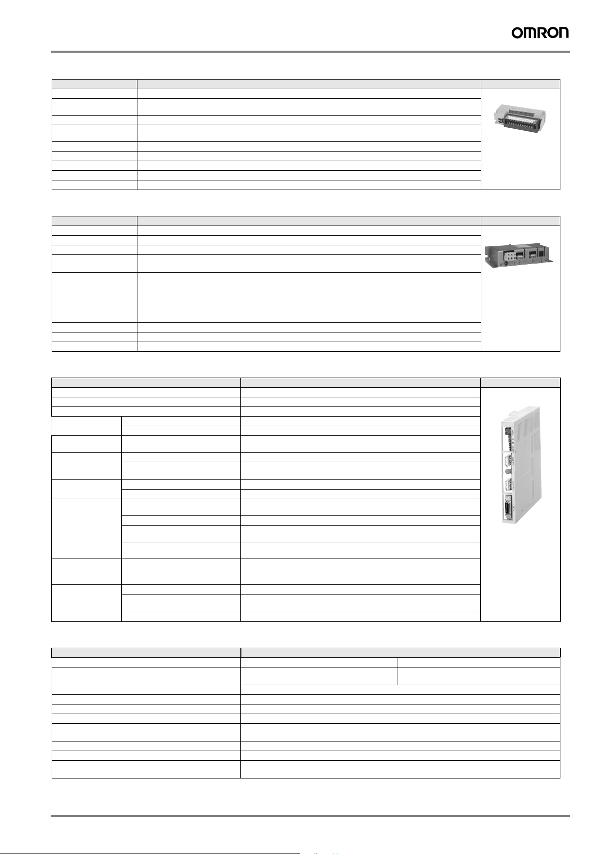
MECHATROLINK-II, analog output module (AN2910)
Items Specifications Appearance
Model JEPMC-AN2910
Number of output
channels
Output voltage range -10V to +10V
Max. allowable
load current
Data format Binary, -32000 to +32000
Output delay time 1ms
Error ± 0.2% F.S. (at 25 °C), ± 0.5% F.S. (at 0 °C to 60 °C)
External power supply 24 VDC (20.4 VDC to 26.4 VDC), 120 mA max.
Weight 300 g
2
± 5 mA (2 kΩ)
MECHATROLINK-II repeater
Items Specifications Appearance
Model JEPMC-REP2000
Communication type MECHATROLINK-II
Cable length Between controller and repeater: 50 m, after repeater: 50 m
Max. connected
stations
Restrictions Between controller and repeater
Power supply 24 VDC, 100 mA
Weight 340 g
Dimensions (mm) 30x160x77 (HxWxD)
Total stations on both sides of repeater: 30
(limited to the max. number of connectable stations of the controller (e.g., 21 stations for the MP2300 series)
- Total cable length
- 30 m < total cable length
After repeater:
- Total cable length
- 30 m < total cable length
≤ 30 m: 15 stations max. including I/O and servo, etc.
≤ 50 m: 14 stations max. including I/O and servo, etc.
≤ 30 m: 16 stations max. including I/O and servo, etc.
≤ 50 m: 15 stations max. including I/O and servo, etc.
MECHATROLINK-II servo drive interface unit
Item Details
Type JUSP-NS115
Applicable servo drive SGDH-@@@E models (version 38 or later)
Installation method Mounted on the SGDH servo drive side: CN10.
Basic
specifications
MECHATROLINK -II
communications
Command format Operation specification Positioning using MECHATROLINK-I/II communications.
Position control
functions
Fully closed
system
specifications
Input signals in the
servo drive
Internal functions Position data latch function Position data latching is possible using phase C, and external signals 1, 2, 3
Power supply method Supplied from the servo drive control power supply.
Power consumption 2 W
Baud rate/transmission cycle 10 Mbps / 1 ms or more. MECHATROLINK-II communications
Reference input MECHATROLINK-I/II communications
Acceleration/deceleration method Linear first/second-step, asymmetric, exponential, S-curve
Fully closed control Position control with fully closed feedback is possible.
Encoder pulse output in the
servo drive
Fully closed encoder pulse signal A quad B line-driver
Maximum receivable frequency
for servo drive
Power supply for fully closed
encoder
Signal allocation
changes possible
Protection Parameters damage, parameter setting errors, communications errors,
LED indicators A: Alarm, R: MECHATROLINK-I/II communicating
Commands: position, speed, torque, parameter read/write, monitor output
5 V differential line-driver output (complies with EIA Standard RS-422A)
1 Mpps
To be prepared by customer.
Forward/reverse run prohibited, zero point return deceleration LS
External latch signals 1, 2, 3
Forward/reverse torque control
WDT errors, fully closed encoder detecting disconnection
NS115
MECHATROLINK-II, frequency inverter interface units
Item Details
Type SI-T/V7 SI-T
Applicable inverter CIMR-V7 / 3G3-MV
Installation method Mounted on the inverter
Power supply Supplied from the inverter
MECHATROLINK-II communications 10 MHz, 0.5 ms to 8 ms for MECHATROLINK-II
Operation Read and write registers, read monitors, inverter operation, speed reference, torque reference
Inputs and outputs The inputs and outputs in the inverter can be read and set by the MLII master
Connectors ML-II bus connector. DPRAM connector for the inverter
Switches Rotary switch for ML-II address (low byte)
(firmware 5740 or newer)
Contact your OMRON sales office for information about firmware compatibility
(G7/F7 only).
Dip switch for: ML-II address (high bit). ML-II/ML-I selection. 17 byte/32 byte data length selection.
CIMR-G7 / CIMR-F7
(firmware 656x/for G7 / 4011 or newer for F7)
PC motion controller 81
Page 6
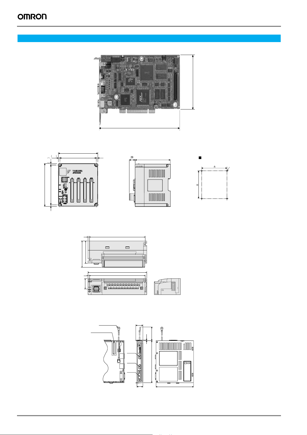
Dimensions
MP2100, MP2100M boards
IO2310 I/O module
4.5 4.5
4.5
121
130
120
111
174.63
108
106.68
Mounting hole diagram
111 0.2
121 0.2
4-tapped holes M4
4.5
I/O modules PL2900, PL2910, AN2900, AN2910
89.8
4.5
79
4.5
44
C
N
1
C
N
2
152
RUNTX 1 2 3 4 5 6 7 8 120 DDI 343 30
161
152
RUN TX 1 2 3 4 5 6 7 8 120 DDI 343 30
MECHATROLINK-II servo drive interface unit
Units: mm Approx. weight: 0.2 kg
FG terminal
M4
Connector
to SERVOPACK
CN6A
CN6B
CN4
24
100
2
NS115
S
W
1
A
R
S
W
2
C
N
6
A
C
N
6
B
C
N
4
20
142
Name
plate
128
82 Motion controllers
Page 7
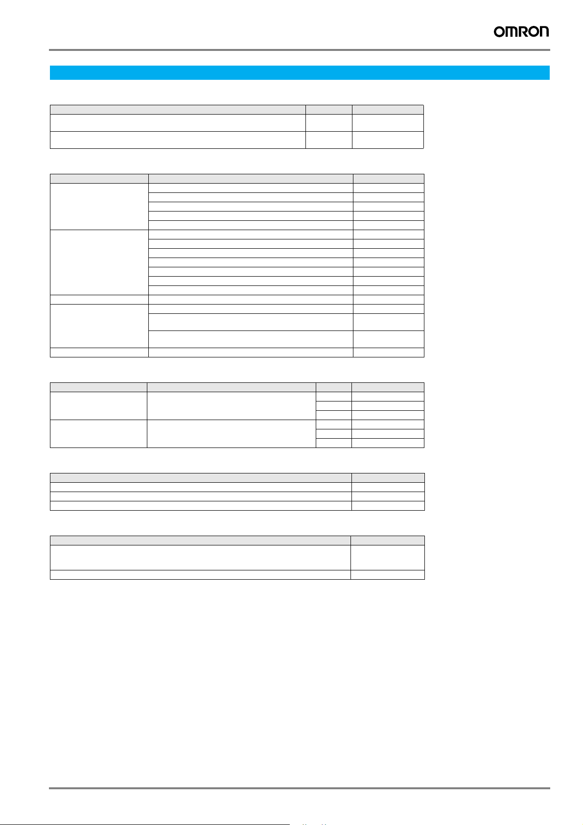
Ordering information
MP2100 - motion controller main units
Name Model name Model
MP2100 board, 1 channel for MECHATROLINK-II communication,
5-point input and 4-point output
MP2100M board, 2 channels for MECHATROLINK-II communication,
5-point input and 4-point output
MECHATROLINK-II - related devices
Name Remarks Model
Distributed I/O modules 64-point input and 64-point output JEPMC-IO2310
MECHATROLINK-II cables 0.5 meter JEPMC-W6003-A5
MECHATROLINK-II terminator Terminating resistor JEPMC-W6022
MECHATROLINK-II
interface unit
MECHATROLINK-II repeater MECHATROLINK-II repeater JEPMC-REP2000
Reversible counter: 2 channels JEPMC-PL2900
Pulse output: 2 channels JEPMC-PL2910
Analog input: -10 V to +10 V, 4 channels JEPMC-AN2900
Analog output: -10 V to +10 V, 2 channels JEPMC-AN2910
1 meter JEPMC-W6003-01
3 meters JEPMC-W6003-03
5 meters JEPMC-W6003-05
10 meters JEPMC-W6003-10
20 meters JEPMC-W6003-20
30 meters JEPMC-W6003-30
For Sigma-II series servo drives. (Firmware version 38 or later) JUSP-NS115
For Varispeed V7 inverter
(for inverter version support contact your OMRON sales office)
For Varispeed F7, G7 inverter
(for inverter version support contact your OMRON sales office)
MP2100 JAPMC-MC2100
MP2100M JAPMC-MC2140
SI-T/V7
SI-T
I/O cables
Name Remarks Lenght m Model
I/O cable for MP2100 With connector on the MP2100 side 0.5 JEPMC-W2062-A5
I/O cable for IO2310 With connector on the IO2310 side 0.5 JEPMC-W5410-05
1.0 JEPMC-W2062-01
3.0 JEPMC-W2062-03
1.0 JEPMC-W5410-10
3.0 JEPMC-W5410-30
Accessories
Name Model
Battery ER3V 3.6V JZSP-BA01
Extended cable for battery with connectors on both sides JEPMC-W2090-01
Brackets for DIN rail JEPMC-OP300
Computer software
Specifications Model
Programming software to support from system design to maintenance.
Intuitive ladder programming and editing functions. CAM data generation
Windows-based (Windows 95/98/NT4.0/2000/XP)
Motion API. Header file, library, DLL, driver, and manual CPMC-MPA70
CPMC-MPE720
Servo system
Note: Refer to servo systems section for detailed information
Frequency inverters
Note: Refer to frequency inverters section for detailed information
PC motion controller 83
Page 8

ALL DIMENSIONS SHOWN ARE IN MILLIMETERS.
To convert millimeters into inches, multiply by 0.03937. To convert grams into ounces, multiply by 0.03527.
Cat. No. I35E-EN-01
In the interest of product improvement, specifications are subject to change without notice.
84 Motion controllers
 Loading...