

Omron MECHATROLINK-II CS1W-MCH71 Datasheet
CS1W-MCH71 - MECHATROLINK-II
Motion control unit
Multi-axes motion control via high-speed
MECHATROLINK-II
• Up to 30 axes controlled with minimum wiring
• High-speed bus MECHATROLINK-II is specially
designed for motion control
• Supports position, speed and torque control
• Electronic CAM profiles and axes synchronization
• Hardware registration input for every axis
• Program control commands, like multi-task, parallel
programming and various arithmetic operations for
maximum program efficiency
• Smart active parts for OMRON HMIs
• Access to the complete system from one point
Function
Multi-axes control is made easy by freely combining control axes. Up to 32 axes can be used, including 30 physical axes and two virtual axes, and
each axis can be set individually. Position control, synchronized control (electronic gear, electronic cam, follow-up), speed control, and torque control are all supported, enabling a wide range of applications. By using the high-speed servo communications MECHATROLINK-II, motion programs, system parameters, system data, and servo drive parameters can be set and read from the software tool.
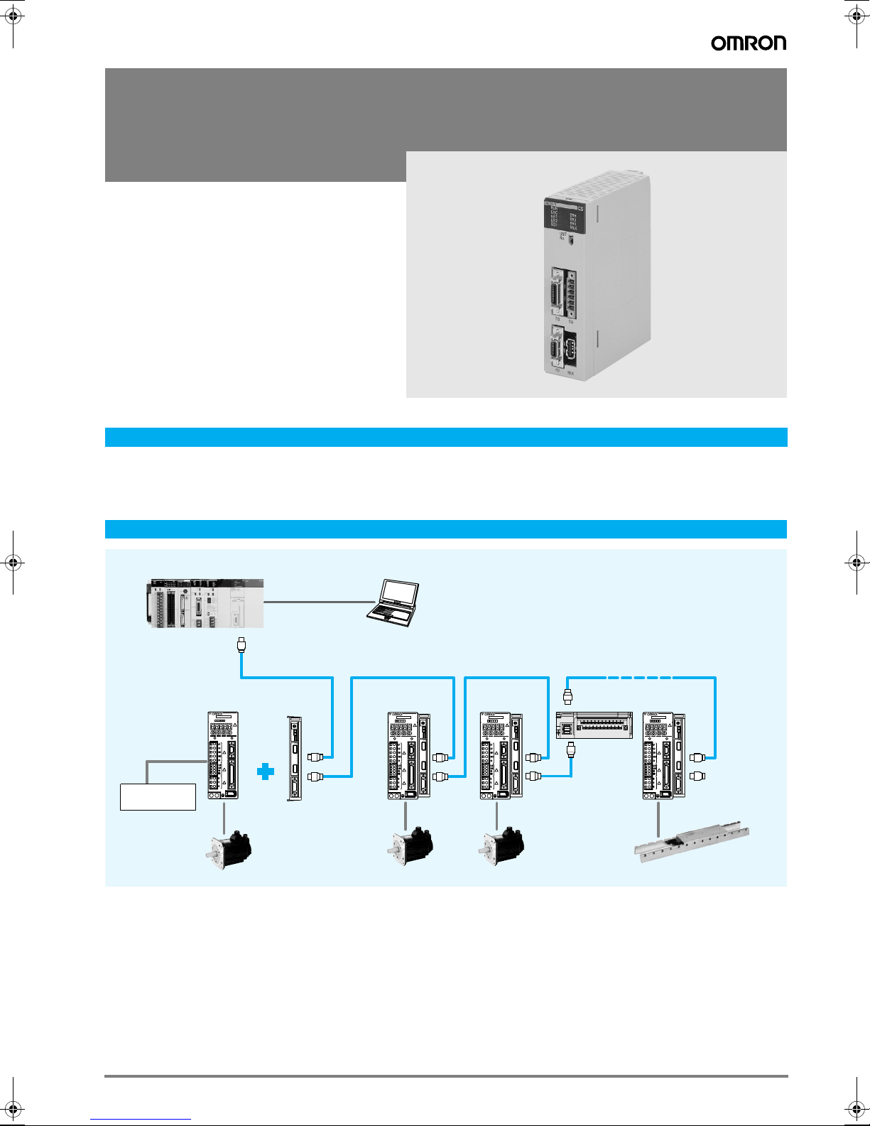
System configuration
CS1 series
Motion control unit
CS1W-MCH71
Sigma-II series
Servo Drive
SERVOPACK
SGDH-
200V
Ver.
CHARGE POWER
Input
Limit switches
contact sensors
CN3
CN1
CN2
NS115
S
W
1
A
R
S
W
2
C
N
6
A
C
N
6
B
C
N
4
JUSP-NS115
Mechatrolink-II
unit
Sigma-II series
Servo Motor
MECHATROLINK-II
SERVOPACK
NS115
SGDH-
200V
Ver.
CHARGE POWER
CN3
CN1
CN2
Personal computer
Software: CX-One
S
W
1
A
R
S
W
2
C
N
6
A
C
N
6
B
C
N
4
SGDH-
Ver.
CHARGE POWER
CN3
CN1
CN2
30 axes max.
Totel length: 50 m
I/O module
SERVOPACK
NS115
S
200V
W
1
A
R
S
W
2
C
N
6
A
C
N
6
B
C
N
4
RUNTX 1 2 3 4 5 6 7 8 120DDI 34330
C
N
1
C
N
2
SERVOPACK
NS115
SGDH-
S
200V
Ver.
W
1
A
R
S
W
2
CHARGE POWER
CN3
C
N
6
A
CN1
C
N
6
B
Terminator
C
N
4
CN2
Sigma-II series
Linear Motor
49Motion control unit
Specifications
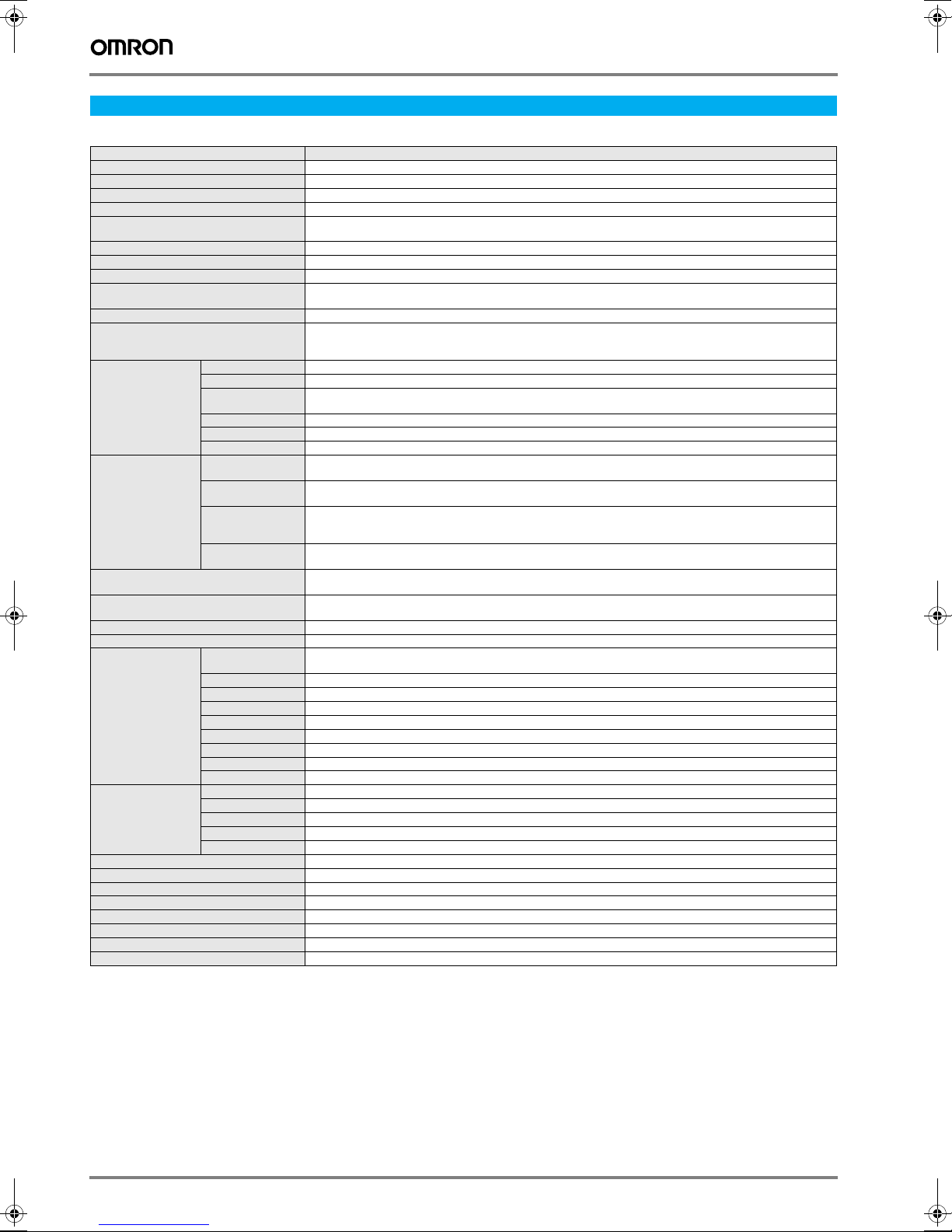
Motion control unit
Model CS1W-MCH71
Classification CS-series CPU bus unit
Applicable PLCs CS-series, (CS1@-CPU@@H)
Backplanes on which MC unit can be mounted CPU backplane or CS-series expansion I/O backplane
Control method MECHATROLINK-II (position, speed and torque control)
Controlled devices Sigma-II series servo drives (ver. 38 or later) with MECHATROLINK-II Interface, various I/O units and inverters V7, F7,
Programming language BASIC type motion control language
Controlled axes 32 max, including 30 physical or virtual axes and 2 virtual axes
Operating modes RUN mode, CPU mode, Tool mode/system (depending on tool)
Automatic/manual mode Automatic mode: mode for executing programs in the unit
Minimum setting unit 1, 0.1, 0.01, 0.001, 0.0001 (unit: mm, inch, degree, pulse)
Maximum command value -2,147,483,648 to 2,147,483,647 pulses (32 bits with sign); infinite axis feed mode supported.
Control functions
by command from
CPU unit
Control functions by
motion program
Acceleration/deceleration curve,
acceleration/deceleration time
External I/O One port for MECHATROLINK-II servo communications, one deceleration stop input, two general inputs,
Feed rate Rapid, interpolation feed rate: 1 to 2,147,483,647 (command units/min)
Override 0.00% to 327.67% (setting unit: 0.01%; can be set for each axis or task.)
Motion
programs
Data exchange
with CPU unit
Saving programs and data Memory card backup (in CPU unit, 100,000 times max.)
Self-diagnostic functions Watchdog, RAM check, etc.
Error detection functions Deceleration stop inputs, unit number errors, CPU errors, software limit errors, etc.
Error log function Read by IORD instruction from CPU unit.
Support software Microsoft Windows 2000 or NT 4.0 (Processor: Pentium, 100 MHz min., with at least 64 MB of memory)
External power supply voltage 24 VDC (21.6 to 26.4 VDC)
Internal current consumption 0.8 A or less for 5 VDC; 0.3 A or less for 24 VDC
Weight (not including connectors) 300 g max.
Servo lock/unlock Locks and unlocks the servo driver.
Jogging Executes continuous feeding for each axis independently at selectable speed.
Origin search Determines the machine origin in the direction set in the system parameters.
Absolute origin setting Sets the origin for when an absolute encoder is used. (Offset value: 32 bits [pulses] with sign)
Machine lock Stops the output of move commands to axes.
Single block Executes motion programs one block at a time.
Positioning (PTP) Executes positioning independently for each axis at a specified speed or the speed system parameter.
Linear interpolation Executes linear interpolation for up to eight axes at a time at the specified interpolation feed speed.
Circular interpolation Executes circular interpolation for two axes in either clockwise or counterclockwise at the specified interpolation
Other functions Origin searches, interrupt feeding, timed positioning, traverse positioning, independent electronic CAM, synchronized
Number of tasks,
number of programs
Program numbers 0000 to 0499 for main program; 0500 to 0999 for subroutine
Program capacity In motion program conversion, 8,000 blocks/unit max. (2 Mbytes); number of blocks: 800 per program
Data capacity Position data: 10,240 points/unit; cam data: 32 max.; 16,000 points/unit
Subroutine nesting Five levels max.
Start Programs in other tasks can be started from a program or from the PLC
Deceleration stop Decelerates to a stop regardless of the block.
Block stop Decelerates to a stop after the block being executed is ended.
Single block Executes the program one block at a time.
Unit BIT area Uses one unit number (25 words). Used for unit and tasks: 11 to 25 words (depending on the number of tasks)
Unit data area Uses one unit number (100 words). Used for unit and tasks: 32 to 74 words (depending on the number of tasks)
Axes BIT area Axes: 0 to 64 words (depending on the maximum axis number used). User configurable.
Axes data area Axes: 0 to 128 words (depending on the maximum axis number used). User configurable.
General purpose General I/O: 0 to 1,280 words (depending on the settings). User configurable.
G7 with MECHATROLINK-II interface (for inverter version support contact your OMRON sales office)
Manual mode: mode for executing commands from the CPU unit (via allocated words)
Example: 16,384 pulses/rev after multiplication, a minimum setting unit of 0.001 mm and 1 mm/rev would result
in -1,310,720,000 to 1,310,719,999 command units.
Can be executed with an absolute encoder.
(Simultaneous specification: up to eight axes/block, simultaneous execution: up to 32 blocks/unit)
(Simultaneous specification: up to eight axes/block, simultaneous execution: up to 32 blocks/system)
feed speed. Helical circular interpolation is also possible with single-axis linear interpolation added.
(Simultaneous specification: two or three axes/block, simultaneous execution: up to 16 blocks/system)
electronic CAM, link operation, electronic gear, follow-up synchronization, speed reference, torque reference
Trapezoidal or S-curve, 60,000 ms max. (S-curve: constant 30,000 ms max.)
two general outputs
Up to 8 tasks and 256 programs/unit (8 parallel branches per task max.)
50 Motion controllers
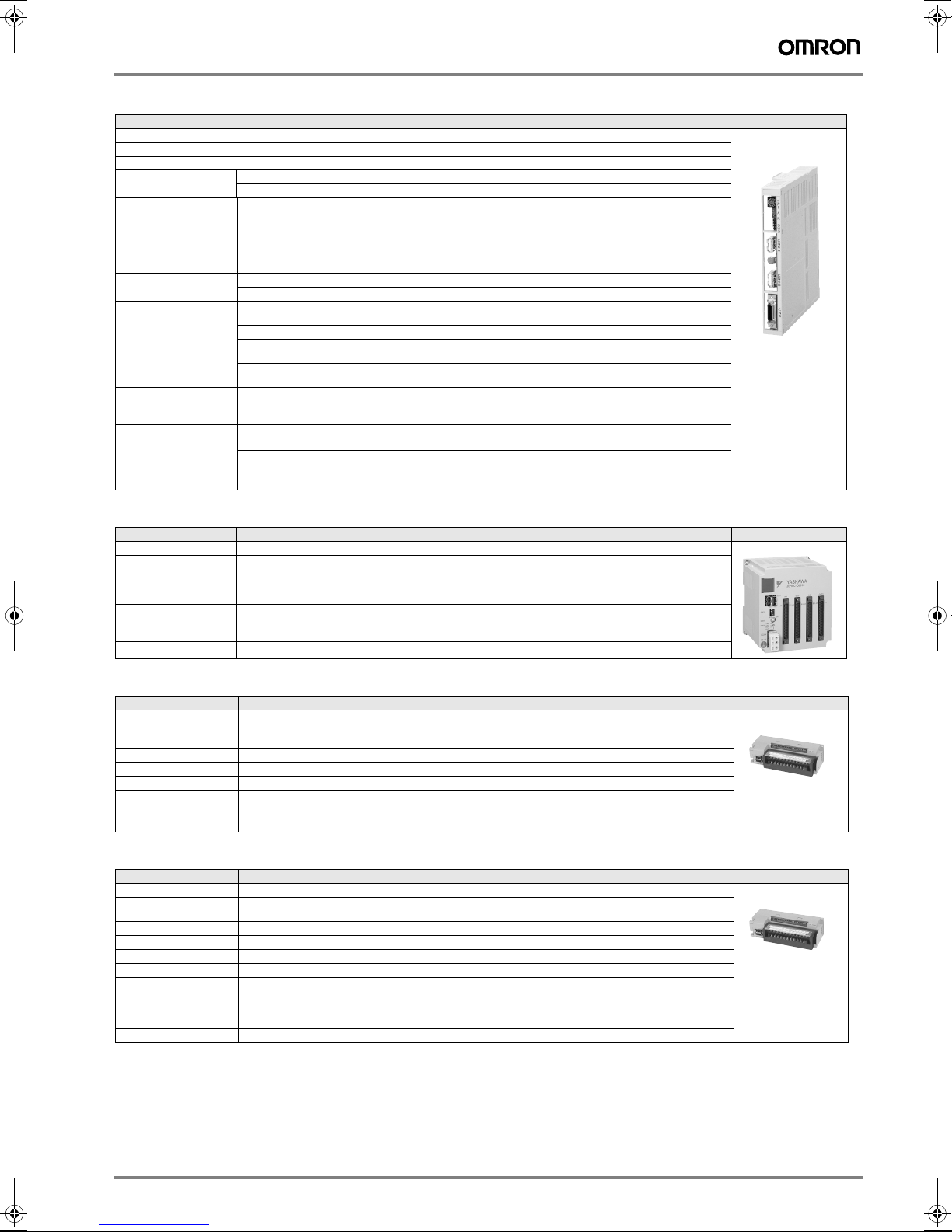
MECHATROLINK-II, servo drive interface unit (JUSP-NS115)
Item Details
Type JUSP-NS115
Applicable servo drive SGDH-@@@E models (version 38 or later)
Installation method Mounted on the SGDH servo drive side: CN10.
Basic
specifications
MECHATROLINK -II
communications
Command format Operation specification Positioning using MECHATROLINK-I/II communications.
Position control
functions
Fully closed
system
specifications
Input signals in the
servo drive
Internal functions Position data latch function Position data latching is possible using phase C,
Power supply method Supplied from the servo drive control power supply.
Power consumption 2 W
Baud rate / transmission cycle 10 Mbps / 1 ms or more. MECHATROLINK-II communications
Reference input MECHATROLINK-I/II communications
Acceleration/deceleration method Linear first/second-step, asymmetric, exponential, S-curve
Fully closed control Position control with fully closed feedback is possible.
Encoder pulse output in the
servo drive
Fully Closed Encoder Pulse Signal A quad B line-driver
Maximum Receivable Frequency
for Servo Drive
Power Supply for Fully Closed
Encoder
Signal allocation changes
possible
Protection Parameters damage, parameter setting errors, communications errors,
LED indicators A: alarm, R: MECHATROLINK-I/II communicating
Commands:position, speed, torque, parameter read/write,
5 V differential line-driver output (complies with EIA standard RS-422A)
1 Mpps
To be prepared by customer.
Forward/reverse run prohibited, zero point return deceleration LS
External latch signals 1, 2, 3
Forward/reverse torque control
and external signals 1, 2, 3
WDT errors, fully closed encoder detecting disconnection
monitor output
NS115
MECHATROLINK-II, 64 point I/O module (IO2310)
Items Specifications Appearance
Model JEPMC-IO2310
I/O signals Input: 64 points, 24 VDC, 5 mA, sink/source mode input
Module power supply 24 VDC (20.4 V to 28.8 V)
Weight 590 g
Output: 64 points, 24 VDC, 50 mA when all points ON,
(the max. rating is 100 mA per point) sink mode output (NPN))
Signal connection method: connector (FCN360 series)
Rated current: 0.5 A
Inrush current: 1 A
MECHATROLINK-II, counter module (PL2900)
Items Specifications Appearance
Model JEPMC-PL2900
Number of input
channels
Functions Pulse counter, notch output
Pulse input method Sign (1/2 multipliers), A/B (1/2/4 multipliers), UP/DOWN (1/2 multipliers)
Max. counter speed 1200 kpps (x 4 multiplier)
Pulse input voltage 3/5/12/24 VDC
External power supply 24 VDC, 120 mA or less
Weight 300 g
2 (1 can be used with MCH)
MECHATROLINK-II, pulse output module (PL2910)
Items Specifications Appearance
Model JEPMC-PL2910
Number of output
channels
Functions Pulse positioning, JOG run, zero-point return
Pulse output method CW, CCW pulse, sign
Max. output speed 500 kpps
Pulse output voltage 5 VDC
Pulse interface circuit Open collector output
External control signal Digital input: 8 points/module, 5 VDC x 4 points, 24 VDC x 4 points
Weight 300 g
2
5 VDC, 10 mA/circuit
Digital output:6 points/module, 5 VDC x 4 points, 24 VDC x 2 points
Motion control unit 51
 Loading...