


ACCURAX G5
Table of contents
 Loading...
Cat. No. I571-E2-01
Accurax G5 servo system
with Analogue/Pulse control
Model:
R88D-KT_ Servo Drives
R88M-K_ Servomotors
USER’S MANUAL


Introduction
Thank you for purchasing the Accurax G5. This user's manual explains how to install and wire
the Accurax G5, set parameters needed to operate the G5, and remedies to be taken and
inspection methods to be used should problems occur.
Intended Readers
This manual is intended for the following individuals.
Those having electrical knowledge (certified electricians or individuals having equivalent or
more knowledge) and also being qualified for one of the following:
Those in charge of introducing FA equipment
Those designing FA systems
Those managing FA sites
Notes
This manual contains the information you need to know to correctly use the Accurax G5 and
peripheral equipment.
Before using the Accurax G5, read through this manual and gain a full understanding of the
information provided herein.
After you finished reading the manual, keep it in a convenient place so that the manual can be
referenced at any time.
Make sure this manual will also get to the end-user.
Introduction
Accurax G5 AC SERVOMOTOR AND SERVO DRIVE USER'S MANUAL
1

Items Requiring Acknowledgment
Items Requiring Acknowledgment
1. Terms of Warranty
(1) Warranty period
The warranty period of this product is 1 year after its purchase or delivery to the
specified location.
(2) Scope of warranty
If the product fails during the above warranty period due to design, material or
workmanship, we will provide a replacement unit or repair the faulty product free of
charge at the location where you purchased the product.
Take note, however, that the following failures are excluded from the scope of
warranty.
a) Failure due to use or handling of the product in any condition or environment not
specified in the catalog, operation manual, etc.
b) Failure not caused by this product
c) Failure caused by any modification or repair not carried out by OMRON
d) Failure caused by any use not intended for this product
e) Failure that could not be predicted with the level of science and technology
available when the product was shipped from OMRON
f) Failure caused by a natural disaster or any other reason for which OMRON is not
held responsible
Take note that this warranty applies to the product itself, and losses induced by a
failure of the product are excluded from the scope of warranty.
2. Limited Liability
(1) OMRON shall not assume any responsibility whatsoever for any special damage,
indirect damage or passive damage arising from this product.
(2) OMRON shall not assume any responsibility for programming done by individuals not
belonging to OMRON, if the product is programmable, or outcomes of such
programming.
3. Conditions for Intended Application
(1) If this product is combined with other product, the customer must check the standards
and regulations applicable to such combination. The customer must also check the
compatibility of this product with any system, machinery or device used by the
customer. If the above actions are not taken, OMRON shall not assume any
responsibility regarding the compatibility of this product.
(2) If the product is used in the following applications, consult your OMRON sales
representative to check the necessary items according to the specification sheet, etc.
Also make sure the product is used within the specified ratings and performance
ranges with an ample margin and implement safety measures, such as designing a
safety circuit, to minimize danger should the product fail.
a) Used in any outdoor application, application subject to potential chemical
contamination or electrical interference, or in any condition or environment not
specified in the catalog, operation manual, etc.
b) Nuclear power control equipment, incineration equipment, railway, aircraft and
vehicle equipment, medical machinery, entertainment machinery, safety system
or any other device controlled by an administrative agency or industry regulation
c) System, machinery or device that may threaten human life or property
d) Gas, water or electricity supply system, system operated continuously for 24
hours or any other equipment requiring high reliability
e) Any other application where a high level of safety corresponding to a) to d) above
is required
(3) If the customer wishes to use this product in any application that may threaten human
life or property, be sure to confirm beforehand that the entire system is designed in
2
Accurax G5 AC SERVOMOTOR AND SERVO DRIVE USER'S MANUAL

Items Requiring Acknowledgment
such a way to notify dangers or ensure the necessary level of safety via design
redundancy, and that the product is wired and installed appropriately in the system
according to the intended application.
(4) Sample applications explained in the catalog, etc. are provided for reference purposes
only. When adopting any of these samples, check the function and safety of each
equipment or device.
(5) Understand all prohibited items and notes on use provided herein, so that this product
will be used correctly and that customers or third parties will not suffer unexpected
losses.
4. Specification Change
The product specifications and accessories explained in the catalog, operation manual,
etc. are subject to change, if necessary, for the reasons of improvement, etc. Contact
your OMRON sales representative to check the actual specifications of this product.
5. Scope of Service
The price of this product excludes costs of service such as dispatching engineers.
If you have any request regarding service, consult your OMRON sales representative.
6. Scope of Application
The above paragraphs are based on the assumption that this product is traded and used
in Japan.
If you wish to trade or use this product outside Japan, consult your OMRON sales
representative.
Accurax G5 AC SERVOMOTOR AND SERVO DRIVE USER'S MANUAL
3
Safety Precautions Document
Safety Precautions Document
So that the Accurax G5 Servomotor and Servo Drive and peripheral equipment are used safely and correctly,
be sure to peruse this Safety Precautions document section and the main text before using the product in order
to learn all items you should know regarding the equipment as well as all safety information and precautions.
Make an arrangement so that this manual also gets to the end-user of this product.
After reading this manual, keep it with you at all times.
Explanation of Display
The precautions explained in this section describe important information regarding safety and must be followed
without fail.
The display of precautions used in this manual and their meanings are explained below.
When an incorrect handling can lead to a dangerous
Danger
situation, which may result in death or serious injury
Or, when a serious property damage may occur
Caution
Even those items denoted by the caution symbol may lead to a serious outcome depending on
the situation. Accordingly, be sure to observe all safety precautions.
This symbol indicates an item you should perform or avoid in order to use the product
safely.
This symbol indicates an item you should perform or avoid in order to prevent
inoperative, malfunction or any negative effect on performance or function.
This symbol indicates an item that helps deepen your understanding of the product or
other useful tip.
Explanation of Symbols
Example of symbols
This symbol indicates danger and caution.
The specific instruction is described using an illustration or text inside or near .
The symbol shown to the left indicates "beware of electric shock".
When an incorrect handling can lead to a dangerous
situation, which may result in a minor or moderate
injury, and when only a property damage may occur
This symbol indicates a prohibited item (item you must not do).
The specific instruction is described using an illustration or text inside or near .
The symbol shown to the left indicates "disassembly prohibited".
This symbol indicates a compulsory item (item that must be done).
The specific instruction is described using an illustration or text inside or near .
The symbol shown to the left indicates "grounding required".
4
Accurax G5 AC SERVOMOTOR AND SERVO DRIVE USER'S MANUAL
Safety Precautions Document
Danger
For Safe Use of This Product
Illustrations contained in this manual sometimes depict conditions without covers and safety shields for the
purpose of showing the details. When using this product, be sure to install the covers and shields as specified
and use the product according to this manual.
If the product has been stored for an extended period of time, contact your OMRON sales representative.
Be sure to ground the frame ground terminals of the driver and motor to 100 Ω or less.
Electric shock may result.
Never touch the parts inside the driver.
Electric shock may result.
While the power is supplied, do not remove the front cover, terminal covers, cables and
options.
Electric shock may result.
Installation, operation and maintenance or inspection by unauthorized personnel is
prohibited.
Electric shock or injury may result.
Before carrying out wiring or inspection, turn OFF the power supply and wait for at least 15
minutes.
Electric shock may result.
Do not damage, pull, stress strongly or pinch the cables or place heavy articles on them.
Electric shock, stopping of product operation or burn damage may result.
Never touch the rotating part of the motor during operation.
Injury may result.
Never modify the product.
Injury or equipment damage may result.
Install a stopping device on the machine side to ensure safety.
* The holding brake is not a stopping device to ensure safety.
Injury may result.
Install an immediate stop device externally to the machine so that the operation can be
stopped and the power supply cut off immediately.
Injury may result.
When the power is restored after a momentary power interruption, the machine may restart
suddenly. Never come close to the machine.
* Implement remedies to ensure safety of people nearby even when the machine is
restarted.
Injury may result.
After an earthquake, be sure to conduct safety checks.
Electric shock, injury or fire may result.
Never drive the motor using an external drive source.
Fire may result.
Accurax G5 AC SERVOMOTOR AND SERVO DRIVE USER'S MANUAL
5
Safety Precautions Document
Caution
Do not place flammable materials near the motor, driver or Regeneration Resistor.
Fire may result.
Install the motor, driver and Regeneration Resistor to non-flammable materials such as
metals.
Fire may result.
When you perform a system configuration using the safety function, be sure to fully
understand the relevant safety standards and the descriptions in the operation manual, and
apply them to the system design.
Injury or damage may result.
Do not use the cable when it is laying in oil or water.
Electric shock, injury or fire may result.
Never connect a commercial power supply directly to the motor.
Fire or failure may result.
Danger
Do not perform wiring or any operation with wet hands.
Electric shock, injury or fire may result.
Do not touch the key grooves with bare hands if a motor with shaft-end key grooves is being
used.
Injury may result.
Use the motor and driver in the specified combination.
Fire or equipment damage may result.
Do not store or install the product in the following environment:
Location subject to direct sunlight
Location where the ambient temperature exceeds the specified level
Location where the relative humidity exceeds the specified level
Location subject to condensation due to the rapid temperature change
Location subject to corrosive or flammable gases
Location subject to higher levels of dust, salt content or iron dust
Location subject to splashes of water, oil, chemicals, etc.
Location where the product may receive vibration or impact directly
Installing or storing the product in these locations may result in fire, electric shock or
equipment damage.
The driver radiator, Regeneration Resistor, motor, etc. may become hot while the power is
supplied or remain hot for a while even after the power supply is cut off. Never touch these
components.
A burn injury may result.
6
Accurax G5 AC SERVOMOTOR AND SERVO DRIVE USER'S MANUAL
Storage and Transportation
Caution
When transporting the product, do not hold it by the cables or motor shaft.
Injury or failure may result.
Do not overload the products. (Follow the instruction on the product label.)
Injury or failure may result.
Use the motor eye-bolts only when transporting the motor.
Do not use them to transport the machine.
Injury or failure may result.
Safety Precautions Document
Accurax G5 AC SERVOMOTOR AND SERVO DRIVE USER'S MANUAL
7
Safety Precautions Document
Caution
Installation and Wiring
Do not step on the product or place heavy articles on it.
Injury may result.
Do not block the intake or exhaust openings. Do not allow foreign objects to enter the
product.
Fire may result.
Be sure to observe the mounting direction.
Failure may result.
Provide the specified clearance between the driver and the inner surface of the control panel
or other equipment.
Fire or failure may result.
Do not apply strong impact on the motor shaft or driver.
Failure may result.
Wire the cables correctly and securely.
Runaway motor, injury or failure may result.
Securely tighten the unit mounting screws, terminal block screws and cable screws.
Failure may result.
Use crimp terminals for wiring.
If simple twisted wires are connected directly to the protective ground terminal, fire may
result.
Only use the power supply voltage specified in this manual.
Burn damage may result.
In locations where the power supply infrastructure is poor, make sure the rated voltage can
be supplied.
Equipment damage may result.
Provide safety measures, such as a breaker, to protect against short circuiting of external
wiring.
Fire may result.
If the product is used in the following locations, provide sufficient shielding measures.
Location where noise generates due to static electricity, etc.
Location where a strong electric or magnetic field generates
Location where exposure to radioactivity may occur
Location where power supply lines are running nearby
Using the product in these locations may result in equipment damage.
Connect an immediate stop relay in series with the brake control relay.
Injury or failure may result.
When connecting the battery, make sure the correct polarity is connected.
Battery damage or explosion may result.
8
Accurax G5 AC SERVOMOTOR AND SERVO DRIVE USER'S MANUAL
Operation and Adjustment
Caution
Conduct a test operation after confirming that the equipment is not affected.
Equipment damage may result.
Before operating the product in an actual environment, check if it operates correctly based
on the parameters you have set.
Equipment damage may result.
Never adjust or set parameters to extreme values, as it will make the operation unstable.
Injury may result.
Separate the motor from the mechanical system and check its operation before installing the
motor to the machine.
Injury may result.
Safety Precautions Document
If an alarm generated, remove the cause of the alarm and ensure safety, and then reset the
alarm and restart the operation.
Injury may result.
Do not use the built-in brake of the motor for normal braking operation.
Failure may result.
Do not operate the Servomotor when an excessive load inertia is installed.
Failure may result.
Install safety devices to prevent idle running or lock of the electromagnetic brake or the gear
head, or leakage of grease from the gear head.
Injury, damage or taint damage may result.
If the driver fails, cut off the power supply to the driver on the power supply side.
Fire may result.
Do not turn ON and OFF the main driver power supply frequently.
Failure may result.
Accurax G5 AC SERVOMOTOR AND SERVO DRIVE USER'S MANUAL
9
Safety Precautions Document
Caution
Maintenance and Inspection
After replacing the unit, transfer to the new unit all data needed to resume operation, before
restarting the operation.
Equipment damage may result.
Never repair the product by disassembling it.
Electric shock or injury may result.
Be sure to turn OFF the power supply when the unit is not going to be used for a prolonged
period of time.
Injury may result.
10
Accurax G5 AC SERVOMOTOR AND SERVO DRIVE USER'S MANUAL
Safety Precautions Document
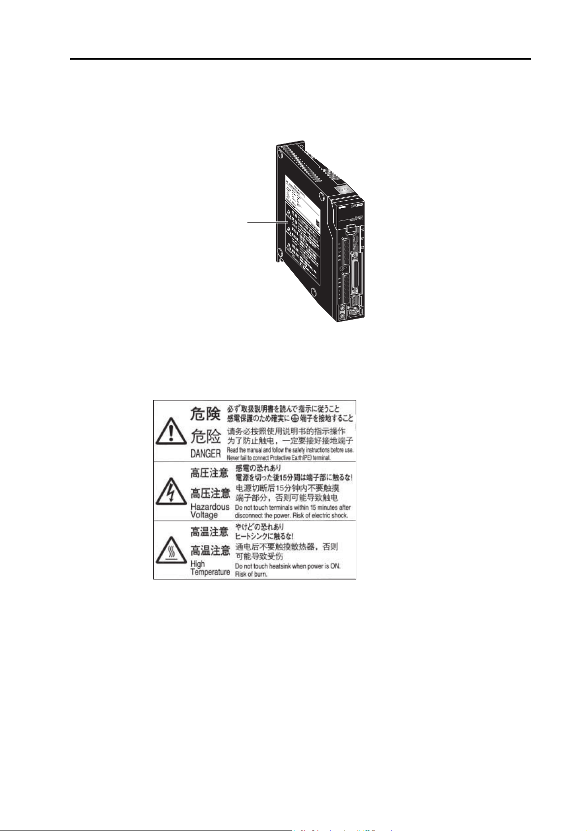
Location of Warning Label
This product bears a warning label at the following location to provide handling warnings.
When handling the product, be sure to observe the instructions provided on this label.
Warning label display location
(R88D-KTA5L)
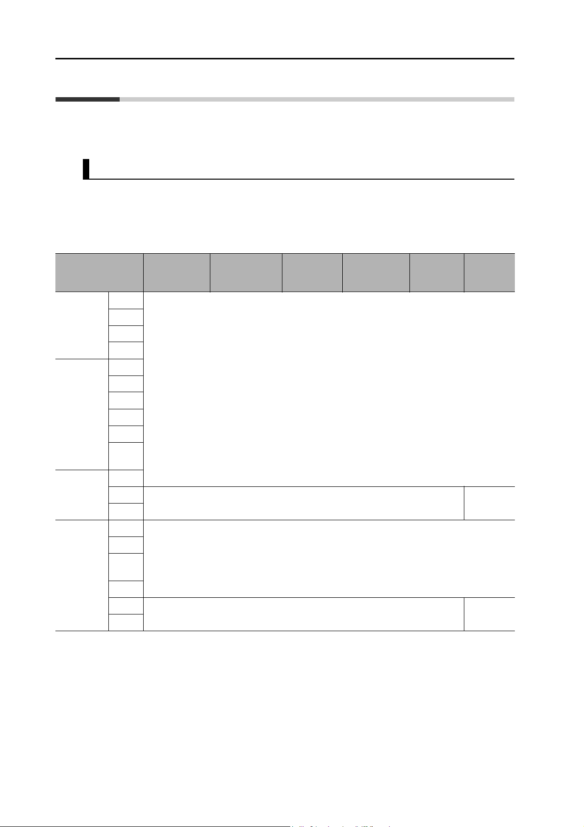
Instructions on Warning Label
Disposal
When disposing of the battery, insulate it using tape, etc. and dispose of it by following the
applicable ordinance of your local government.
Dispose of the product as an industrial waste.
Accurax G5 AC SERVOMOTOR AND SERVO DRIVE USER'S MANUAL
11
Items to Check after Unpacking
Items to Check after Unpacking
After unpacking, check the following items.
Is this the model you ordered?
Is there any damage sustained during shipment?
Accessories of This Product
Safety Precautions document x 1 copy
Connectors, mounting screws, etc. other than those in the table below are not supplied. They
must be prepared by the customer.
If any item is missing or a problem is found such as Servo Drive damage, contact the
OMRON dealer or sales office where you purchased your product.
Specifications
Singlephase 100
VAC
Singlephase/3phase 200
VAC
3-phase
200 VAC
3-phase
400 VAC
50 W
100 W
200 W
400 W
100 W
200 W
400 W
750 W
1 kW
1.5
kW
2 kW
3 kW
5 kW
600 W
1 kW
1.5
kW
2 kW
Main power
supply
connector
Included
− Included
Included
Control power
supply
connector
Motor
connector
Regeneration
Resistor
connector
Open
software
Safety
bypass
connector
12
3 kW
− Included
5 kW
Accurax G5 AC SERVOMOTOR AND SERVO DRIVE USER'S MANUAL
Manual Revision History
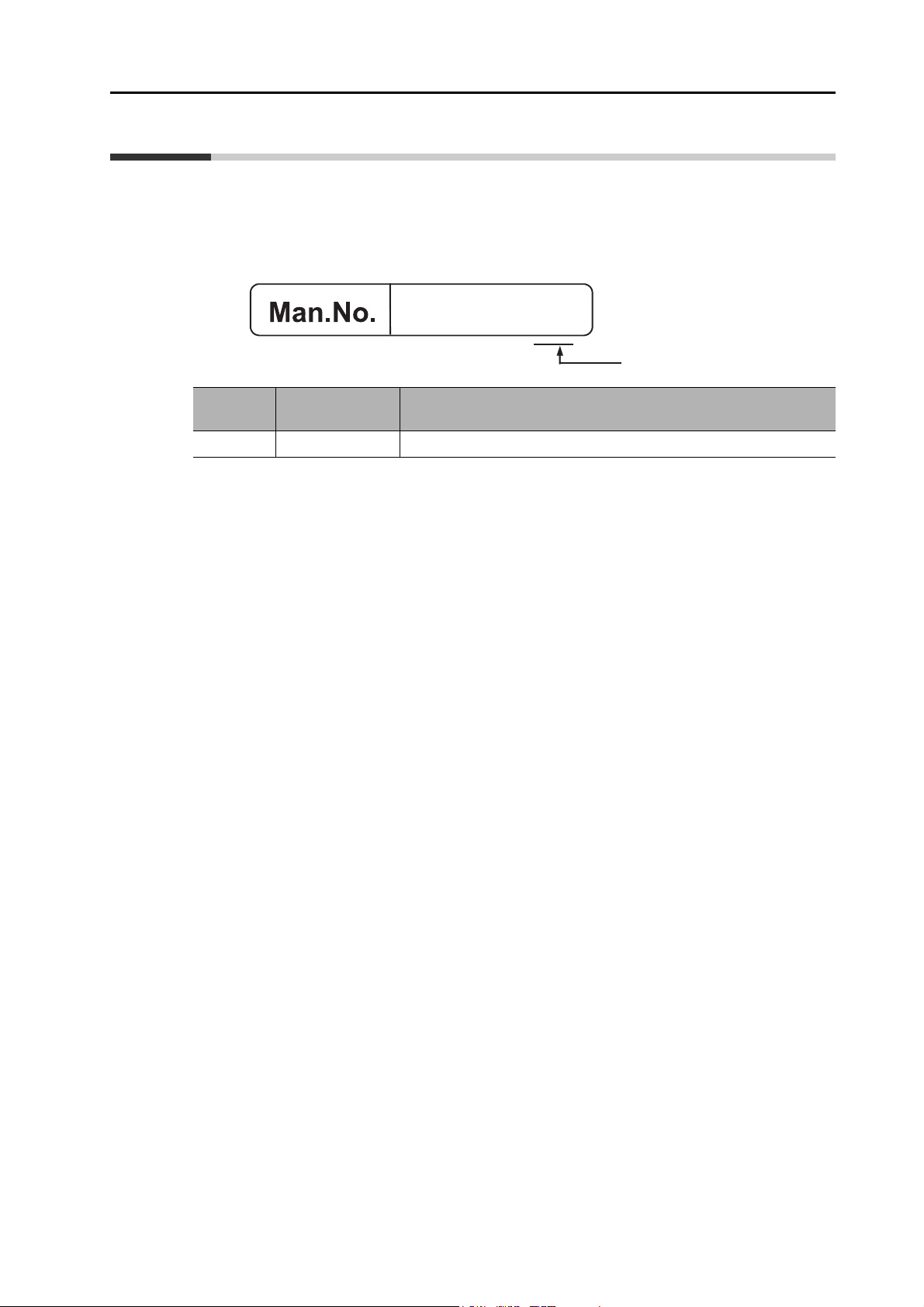
The manual revision symbol is an alphabet appended at the end of the manual number found
in the bottom left-hand corner of the front or back cover.
Example
I571-E2-01
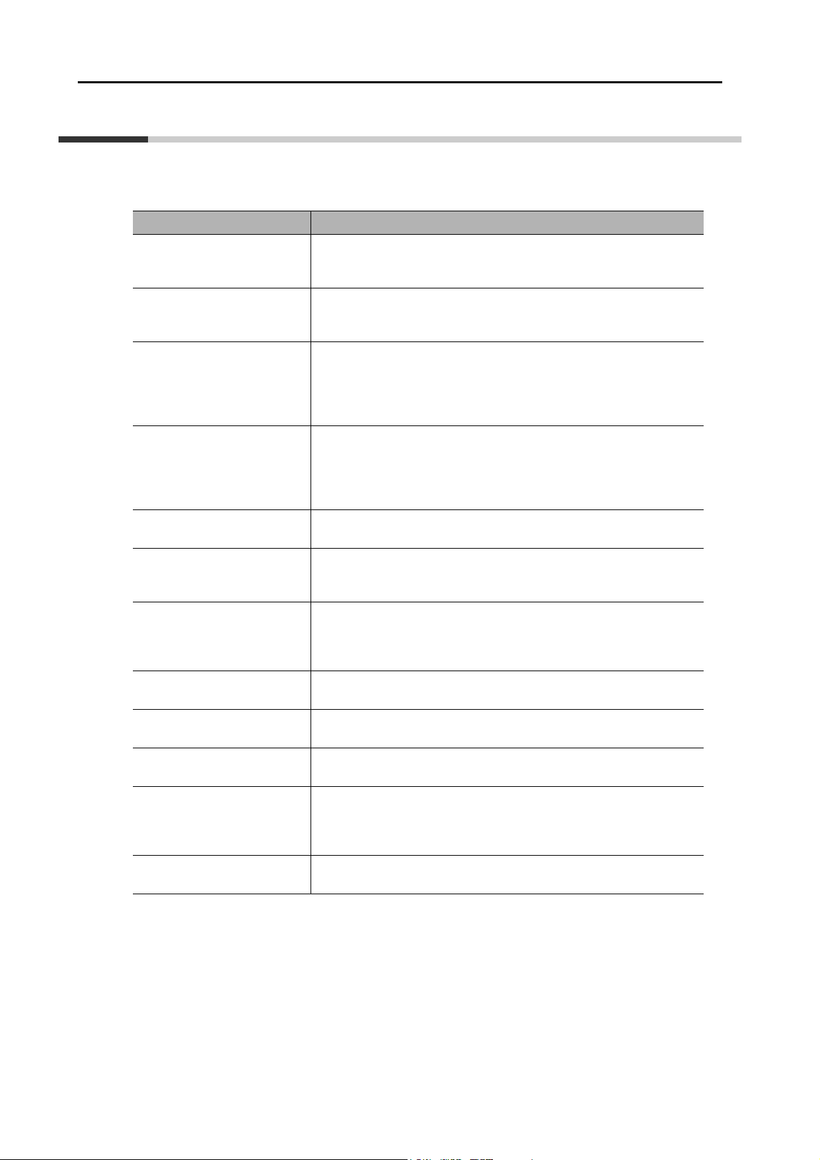
Manual Revision History
Revision symbol
Revision
symbol
01 February 2010 First Print. European version
Revision date Description of revision and revised page
Accurax G5 AC SERVOMOTOR AND SERVO DRIVE USER'S MANUAL
13
Structure of This Document
This manual consists of the following chapters.
Read the necessary chapter or chapters referring to below.
Outline
Features and
Chapter 1
Chapter 2
Chapter 3 Specifications
Chapter 4 System Design
Chapter 5
Chapter 6
Chapter 7 Safety Function
System
Configuration
Standard Models
and External
Dimensions
BASIC
CONTROL mode
Applied
Functions
This chapter explains the features of this product, name of each part,
and applicable EC directives and UL standards.
This chapter explains the models of Servo Drive, Servomotor, and
peripheral equipment, as well as the external dimensions and
mounting dimensions.
This chapter explains the general specifications, characteristics,
connector specifications and I/O circuits of the Servo Drive, general
specifications, characteristics, encoder specifications of the
Servomotor, and all other specifications including those of peripheral
equipment.
This chapter explains the installation conditions, wiring methods
including wiring conforming to EMC directives and regenerative energy
calculation methods regarding the Servo Drive, Servomotor and
Decelerator, as well as the performance of External Regeneration
Resistors, and so on.
This chapter explains an outline of operations available in various
CONTROL modes and explains the contents of setting.
This chapter gives outline of applied functions such as damping
control, electronic gears, gain switching and disturbance observer, and
explains the contents of setting.
This function stops the motor based on a signal from a Safety
Controller or safety sensor.
An outline of the function is explained together with operation and
connection examples.
Chapter 8
Chapter 9 Operation
Chapter 10
Chapter 11
Chapter 12 Appendix
Parameters
Details
Adjustment
Functions
Error and
Maintenance
This chapter explains the set value and contents of setting of each
parameter.
This chapter explains the operating procedures and how to operate in
each mode.
This chapter explains the functions, setting methods and items to note
regarding various gain adjustments.
This chapter explains the items to check when problems occur, error
diagnosis using the alarm LED display and measures, error diagnosis
based on the operating condition and measures, and periodic
maintenance.
This chapter provides connection examples using OMRON's PLC and
Position Controller, as well as a list of parameters.
14

Accurax G5 AC SERVOMOTOR AND SERVO DRIVE USER'S MANUAL
15

Table Of Contents
Introduction ......................................................................................1
Items Requiring Acknowledgment ................................................... 2
Safety Precautions Document ......................................................... 4
Items to Check after Unpacking....................................................... 12
Manual Revision History .................................................................. 13
Structure of This Document ............................................................. 14
Chapter1 Features and System Configuration
1-1 Outline ................................................................................................1-2
1-2 System Configuration .........................................................................1-3
1-3 Names and Functions......................................................................... 1-4
1-4 System Block Diagrams...................................................................... 1-6
1-5 Applicable Standards.......................................................................... 1-11
Chapter2 Standard Models and External Dimensions
2-1 Servo System Configuration ............................................................... 2-2
2-2 How to Read Model ............................................................................2-4
2-3 Standard Model List............................................................................ 2-6
2-4 External and Mounting Dimensions .................................................... 2-25
2-5 EMC Filter Dimensions ....................................................................... 2-57
Chapter3 Specifications
3-1 Driver Specifications ........................................................................... 3-2
3-2 Overload Characteristics (Electronic Thermal Function) .................... 3-54
3-3 Motor Specifications ...........................................................................3-55
3-4 Cable and Connector Specifications................................................... 3-84
3-5 Servo Relay Units and Cable Specifications ......................................3-113
3-6 External Regeneration Resistor Specifications................................... 3-132
3-7 EMC Filter Specifications.................................................................... 3-134
Chapter4 System Design
4-1 Installation Conditions......................................................................... 4-2
4-2 Wiring.................................................................................................. 4-8
4-3 Wiring Conforming to EMC Directives ................................................ 4-22
4-4 Regenerative Energy Absorption........................................................ 4-36
Chapter5 BASIC CONTROL Mode
5-1 Position Control ..................................................................................5-2
5-2 Speed Control..................................................................................... 5-8
5-3 Torque Control.................................................................................... 5-14
5-4 Internally Set Speed Control............................................................... 5-19
5-5 Switching Control................................................................................ 5-22
5-6 Full Closing Control ............................................................................5-25
16 Accurax G5 AC SERVOMOTOR AND SERVO DRIVE USER'S MANUAL

Table Of Contents
Chapter6 Applied Functions
6-1 Anti-vibration Control .......................................................................... 6-3
6-2 Adaptive Filter..................................................................................... 6-7
6-3 Notch Filter ......................................................................................... 6-9
6-4 Electronic Gear Function .................................................................... 6-12
6-5 Encoder Dividing Function.................................................................. 6-15
6-6 Brake Interlock.................................................................................... 6-20
6-7 Gain Switching Function..................................................................... 6-25
6-8 Gain Switching 3 Function.................................................................. 6-33
6-9 Torque Limit........................................................................................ 6-34
6-10 Sequence I/O Signal........................................................................... 6-37
6-11 Forward and Reverse Drive Prohibition Functions ............................. 6-43
6-12 Disturbance Observer Function.......................................................... 6-46
6-13 Friction Torque Compensation Function ............................................ 6-48
6-14 Inertia Ratio Switching Function ......................................................... 6-50
6-15 Hybrid Vibration Suppression Function .............................................. 6-52
6-16 Feed-forward Function ....................................................................... 6-53
6-17 Instantaneous Speed Observer Function ........................................... 6-57
Chapter7 Safety Function
7-1 Safe Torque OFF (STO) Function ...................................................... 7-2
7-2 Operation Example............................................................................. 7-5
7-3 Connection Example .......................................................................... 7-7
Chapter8 Parameters Details
8-1 Basic Parameters ............................................................................... 8-2
8-2 Gain Parameters ................................................................................ 8-10
8-3 Vibration Suppression Parameters..................................................... 8-21
8-4 Analog Control Parameters ................................................................ 8-26
8-5 Interface Monitor Setting Parameters................................................. 8-36
8-6 Extended Parameters......................................................................... 8-46
8-7 Special Parameters ............................................................................ 8-59
Chapter9 Operation
9-1 Operational Procedure ....................................................................... 9-2
9-2 Preparing for Operation ...................................................................... 9-3
9-3 Using the Front Display ...................................................................... 9-7
9-4 Setting the Mode ................................................................................ 9-8
9-5 Trial Operation.................................................................................... 9-34
Chapter10 Adjustment Functions
10-1 Gain Adjustment ................................................................................. 10-2
10-2 Realtime Autotuning ........................................................................... 10-4
10-3 Manual Tuning.................................................................................... 10-11
17Accurax G5 AC SERVOMOTOR AND SERVO DRIVE USER'S MANUAL

Table Of Contents
Chapter11 Error and Maintenance
11-1 Error Processing................................................................................. 11-2
11-2 Warning List........................................................................................ 11-5
11-3 Alarm List............................................................................................ 11-6
11-4 Troubleshooting.................................................................................. 11-11
11-5 Periodic Maintenance ......................................................................... 11-22
Chapter12 Appendix
12-1 Connection Examples......................................................................... 12-2
12-2 Parameter List .................................................................................... 12-12
12-3 Safety Certification ............................................................................. 12-33
Index
18 Accurax G5 AC SERVOMOTOR AND SERVO DRIVE USER'S MANUAL

Features and System Configuration
This chapter explains the features of this product, name of each part, and
applicable EC directives and UL standards.
1-1 Outline ...........................................................................1-2
Outline of the Accurax G5 ............................................................... 1-2
Features of the Accurax G5 ............................................................ 1-2
1-2 System Configuration ..................................................1-3
1-3 Names and Functions ..................................................1-4
Driver Part Names .......................................................................... 1-4
Driver Functions.............................................................................. 1-5
1-4 System Block Diagrams...............................................1-6
1-5 Applicable Standards .................................................1-11
EC Directives ................................................................................ 1-11
UL and cUL Standards.................................................................. 1-11
Functional Safety .......................................................................... 1-11
1
Accurax G5 AC SERVOMOTOR AND SERVO DRIVE USER'S MANUAL

1
1-1 Outline
1-1 Outline
Outline of the Accurax G5
With the Accurax G5, you can perform full closing control in addition to position control, speed
control and torque control.
Various models are available supporting wide-ranging motor capacities from 50 W to 5 kW and input
power supplies from 100 to 400 V. You will surely find a model that best suits your application.
Motors with high-resolution 20-bit incremental encoders and 17-bit absolute/incremental
encoders are available as standard models.
The Accurax G5 features realtime autotuning function and adaptive filter function that
automatically perform complicated gain adjustments. A notch filter can also be automatically
set to suppress machine vibration by reducing machine resonance during operation.
The damping control function of the Servomotor and Servo Drive realizes stable stopping
performance in a mechanism which vibrates because of the low rigidity of the load.
Features of the Accurax G5
The Accurax G5 has the following features.
7 Possible CONTROL modes Switching
You can switch among 7 CONTROL modes including the following: (1) position control, (2)
speed control, (3) torque control, (4) position and speed control, (5) position and torque control,
(6) speed and torque control, (7) full closing control. Desired modes can be selected with the
flexible driver according to your need. A single driver supports various applications.
Features and System Configuration
Achievement of Accurate Positioning by Full Closing Control
Feedbacks from the external scale connected to the motor are used to accurately control positions.
Accordingly, position control is not affected by deviation caused by ball screws or temperature.
Wide Range of Power Supplies to Match Any Necessity
The Accurax G5 now has models supporting 400 V for use with large equipment, at overseas
facilities and in wide-ranging applications and environment. Since the utilization ratio of facility
equipment also increases, the TCO (Total Cost of Ownership) will come down.
Safe Torque OFF (STO) Function to Ensure Safety
You can cut off the motor current to stop the motor based on a signal from an immediate stop
button or other safety equipment. In addition to the conventional stop method based on a
control signal, the STO function that permits direct stopping without a need to involve the
control circuit provides the immediate stop from 2 systems, thereby enhancing safety.
1-2
Suppressing Vibration of Low-rigidity Mechanisms during Acceleration/Deceleration
The damping control function suppresses vibration of low-rigidity mechanisms or devices
whose tips tend to vibrate.
2 vibration filters are provided to enable switching the vibration frequency automatically
according to the rotation direction and also via an external signal. In addition, the settings can
be made easily merely by just setting the vibration frequency and filter values, and you are
assured of stable operation even if the set values are inappropriate.
Accurax G5 AC SERVOMOTOR AND SERVO DRIVE USER'S MANUAL
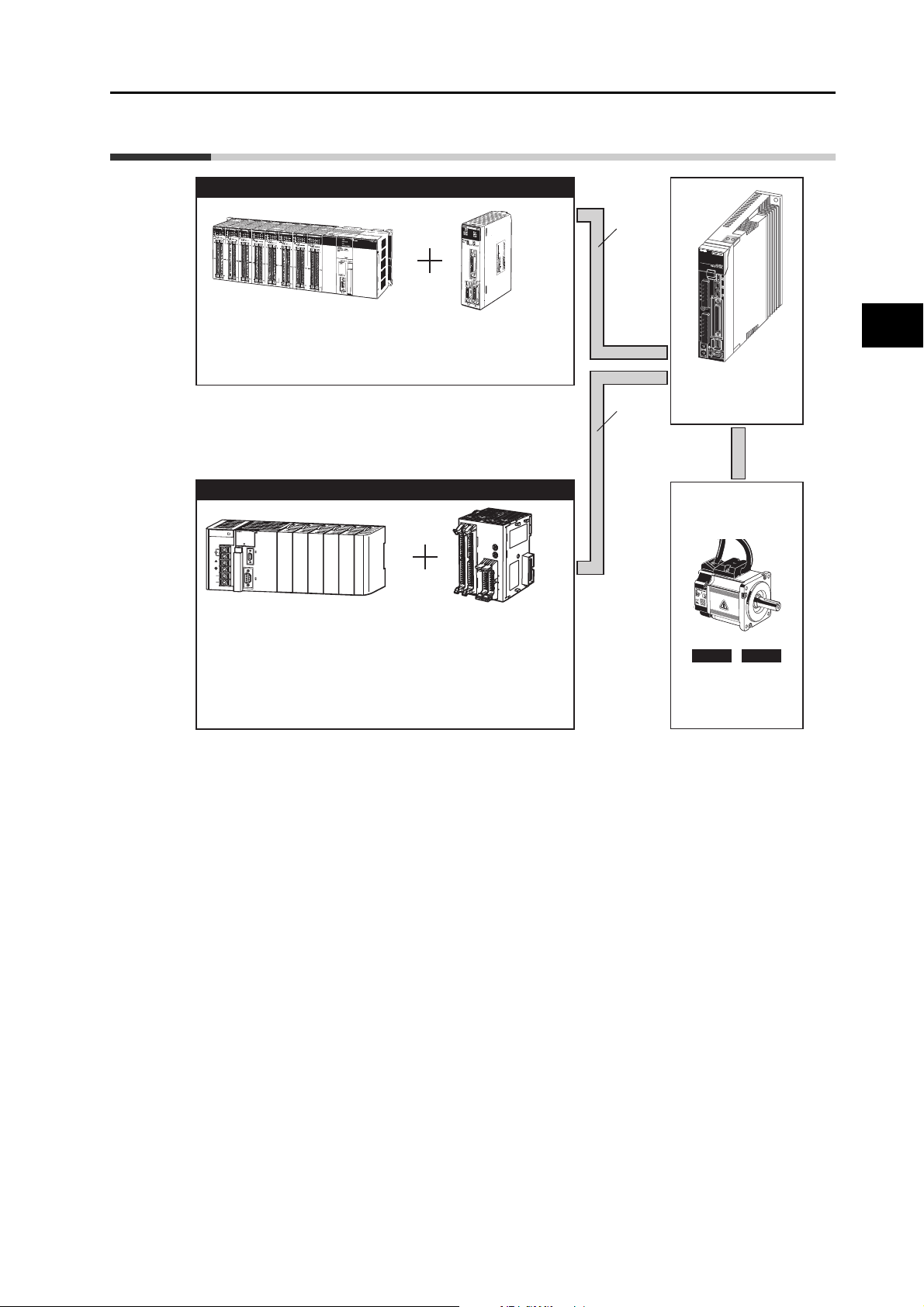
1-2 System Configuration
Controller (Voltage Output Type)
1-2 System Configuration
Analog
voltage
Programmable
Controller
Motion Control Unit
CS1W-MC221/421 (-V1)
SYSMAC CS
SYSMAC + Position Control Unit (Pulse Train Output Type)
N
C
4
1
4
C
N
1
C
N
2
R
U
N
S
Y
N
C
E
R
C
E
R
H
1
2
3
A
1
4
A
2
B
A
1
3
B
A
2
4
A
PA2
02
S
Y
R
U
S
N
M
A
C
P
O
W
E
R
E
R
R
/
A
L
M
C
J
1
G
C
P
U
4
4
I
N
H
PROGRAMM
AB
LE
P
R
P
H
L
CONTROLL
ER
C
O
M
M
O
P
E
N
M
C
P
W
R
L1
B
U
S
Y
AC100
-240V
INPUT
L2/N
P
E
R
IP
H
E
R
A
L
NC
NC
P
O
R
T
Programmable
Controller
SYSMAC CJ/CS
Position Control Unit
CJ1W-NC113/213/413
CJ1W-NC133/233/433
CJ1W-NC214/414
B
S
3
B
4
B
S
M
A
CH
N
o.
IS1
1
x1
0
X
A
0
x10
C
N
3
C
N
4
2
IS
X
A
AXIS2 AXIS1
CJ1W-NC234/434
CS1W-NC113/213/413
CS1W-NC133/233/433
C200HW-NC113/213/413
The following units support a motor with absolute encoder:
CJ1W-NC214/414
CJ1W-NC234/434
CS1W-MC221/421 (-V1)
Pulse
train
'Accurax G5
AC Servomotor
R88D-KTx
INC ABS
'Accurax G5
AC Servomotor
R88M-Kx
1
Features and System Configuration
Accurax G5 AC SERVOMOTOR AND SERVO DRIVE USER'S MANUAL
1-3
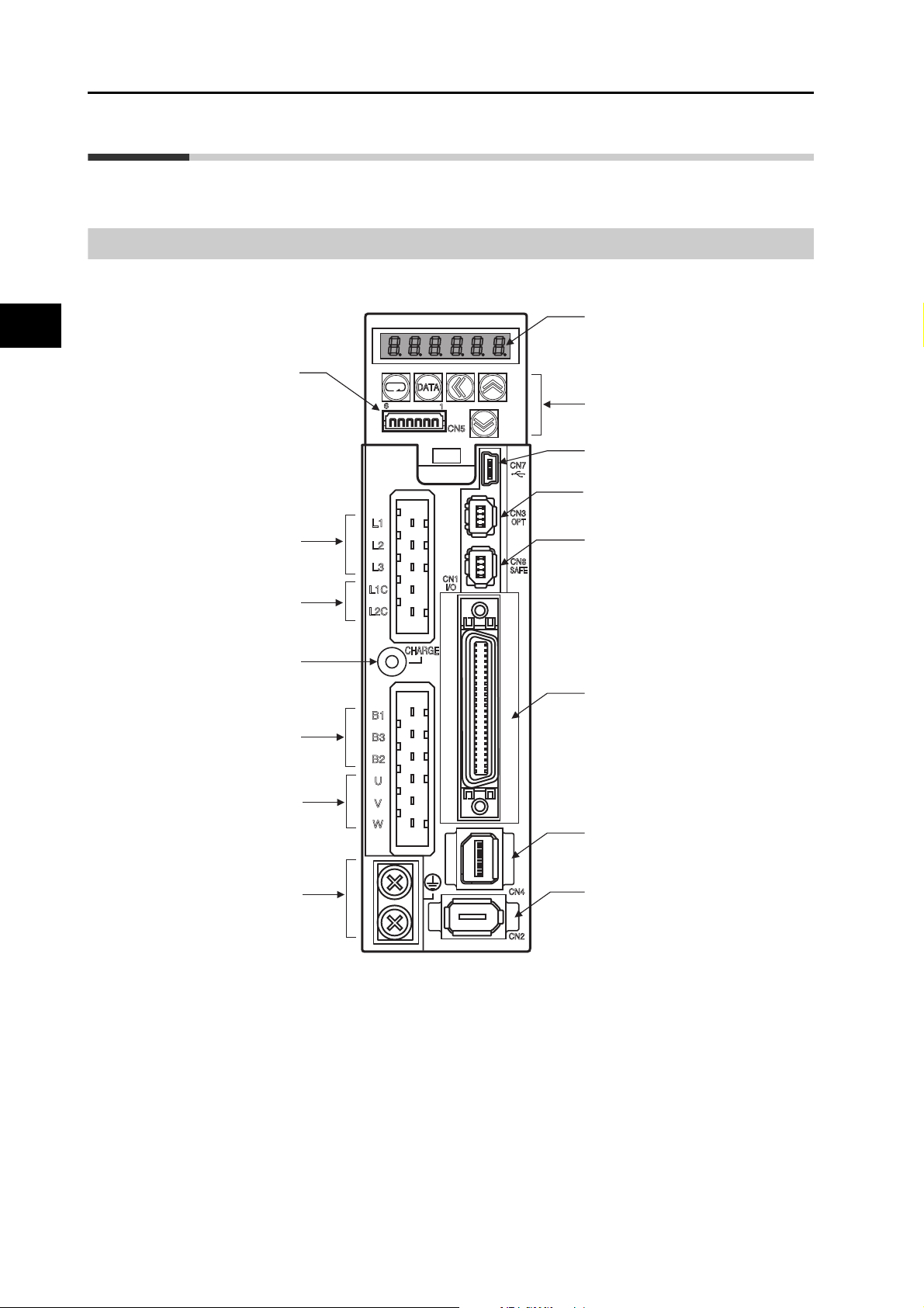
1-3 Names and Functions
1-3 Names and Functions
Driver Part Names
1
Monitor connector (CN5)
Main circuit
power supply terminals
(L1, L2, and L3)
Control circuit
power supply terminals
(L1C and L2C)
Charge lamp
External Regeneration
Resistor connection
Features and System Configuration
terminals (B1, B2 and B3)
Display area
Operation area
USB connector (CN7)
Expansion connector (CN3)
Safety connector (CN8)
Control I/O connector (CN1)
Motor connection
terminals (U, V and W)
Protective ground terminals
External scale connector (CN4)
Encoder connector (CN2)
1-4
Accurax G5 AC SERVOMOTOR AND SERVO DRIVE USER'S MANUAL

Driver Functions
Display Area
A 6-digit 7-segment LED display shows the driver status, alarm codes, parameters, and other
information.
1-3 Names and Functions
Operation Area
Monitors the parameter setting and driver condition.
Charge Lamp
Lits when the main circuit power supply is turned ON.
Control I/O Connector (CN1)
Used for command input signals and I/O signals.
Encoder Connector (CN2)
Connector for the encoder installed in the Servomotor.
Expansion Connector (CN3)
A spare connector for expansion. Do not connect anything.
1
Features and System Configuration
External Scale Connector (CN4)
Connector for an encoder signal used during full closing control.
Monitor Connector (CN5)
2 analog outputs to monitor values like motor rotation speed, torque command value, etc.
USB Connector (CN7)
Communications connector for the computer.
Safety Connector (CN8)
Connector for the safety devices.
If no safety device is used, keep the factory-set safety bypass connector installed.
Accurax G5 AC SERVOMOTOR AND SERVO DRIVE USER'S MANUAL
1-5
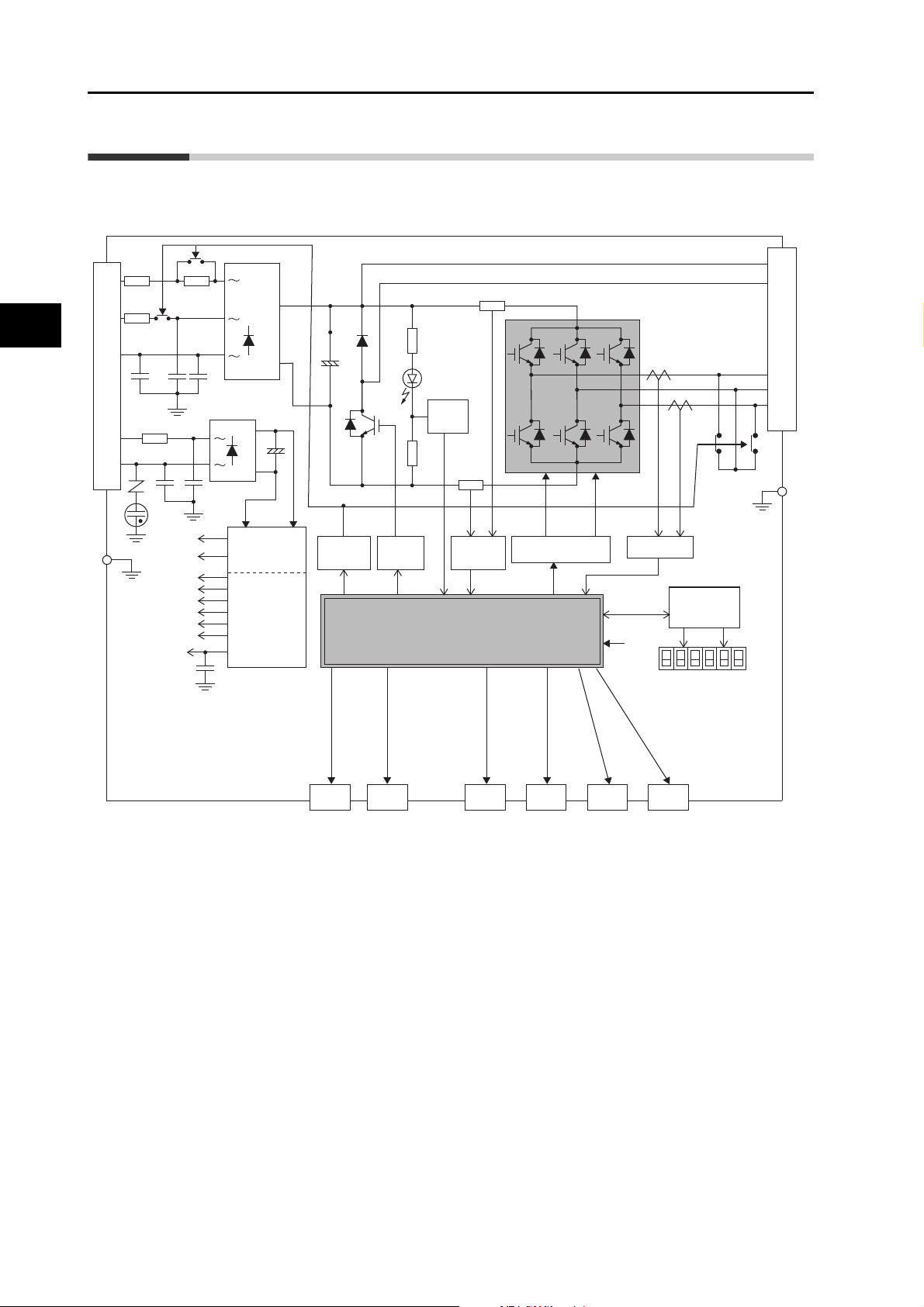
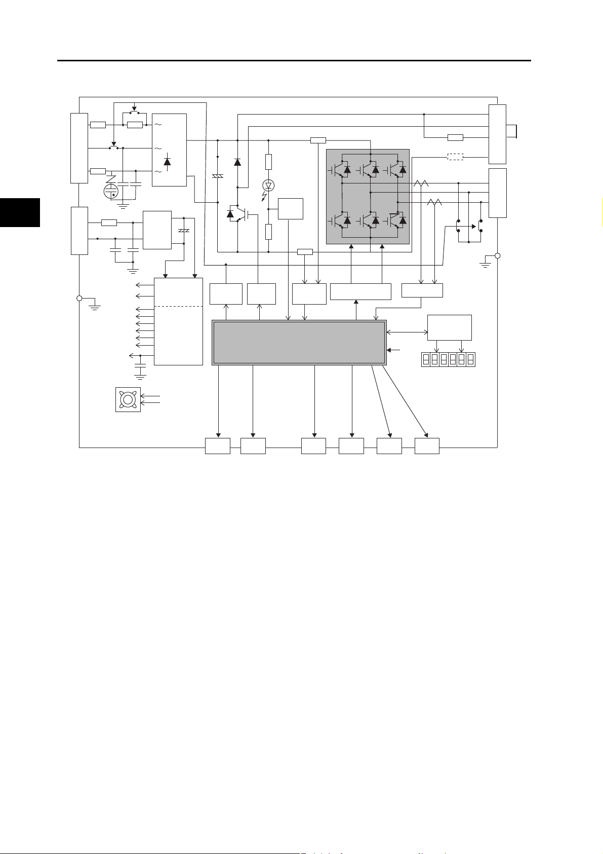
1-4 System Block Diagrams
1-4 System Block Diagrams
Size A: R88D-KTA5L/-01L/-02H
Size B: R88D-KT02L/-04H
Size C: R88D-KT04L/KT08H
1
L1
L2
L3
L1C
L2C
CN A
FUSE
FUSE
GR
GR
FUSE
15 V
G1
5 V
3.3 V
2.5 V
1.5 V
E5 V
±12 V
G2
+
−
+
−
SW power
supply main
circuit control
Internal
control power
supply
Vol tage
detection
Relay
drive
Regeneration
control
MPU&ASIC
Position, speed and torque calculation control area
• PWM control
Overcurrent
detection
Gate drive
Current detection
Display and
setting circuit
area
CN B
B1
B2
B3
U
V
W
GR
Features and System Configuration
CN1
Control
interface
CN2 CN4 CN5 CN7
Encoder
External
scale
Analog
monitor
CN8
USB Safety
1-6
Accurax G5 AC SERVOMOTOR AND SERVO DRIVE USER'S MANUAL
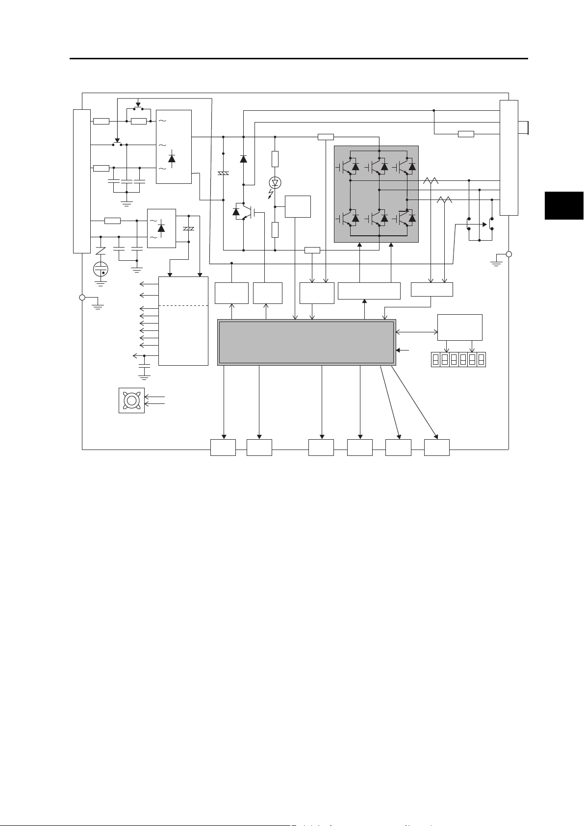
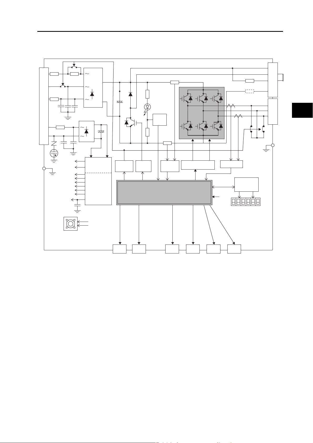
Size D: R88D-KT10H/-15H
1-4 System Block Diagrams
L1
L2
L3
L1C
L2C
CN A
FUSE
FUSE
GR
GR
FUSE
15 V
G1
5 V
3.3 V
2.5 V
1.5 V
E5 V
±12 V
G2
+
−
+
−
SW power
supply main
circuit control
Internal
control power
supply
Vol tage
detection
Relay
drive
Regeneration
control
MPU&ASIC
Position, speed and torque calculation control area
• PWM control
Overcurrent
detection
Gate drive
Internal Regeneration
Resistor
Current detection
Display and
setting circuit
area
CN B
B1
B2
B3
U
V
W
1
Features and System Configuration
GR
Cooling fan
CN1
Control
interface
CN2 CN4 CN5 CN7
Encoder
External
scale
Analog
monitor
CN8
USB Safety
Accurax G5 AC SERVOMOTOR AND SERVO DRIVE USER'S MANUAL
1-7
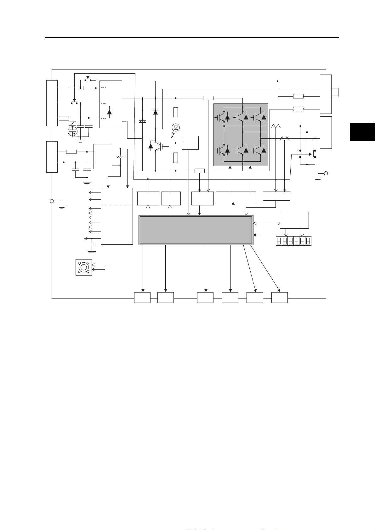
1
Display and
setting circuit
area
Gate drive
SW power
supply main
circuit control
Internal
control power
supply
0V
24V
L3
L2
L1
FUSE
FUSE
FUSE
CN A
+
−
+
−
15 V
G1
5 V
2.5 V
1.5 V
±12 V
E5 V
G2
3.3 V
Overcurrent
detection
Current detection
Voltage
detection
Regeneration
control
Relay
drive
GR
Control
interface
CN2 CN4 CN5 CN7
B1
B2
B3
CN D
U
V
W
MPU&ASIC
Position, speed and torque calculation control area
• PWM control
CN8
Encoder
External
scale
Analog
monitor
USB Safety
CN1
Internal Regen Resistor
Cooling fan
N
CN B
Fuse (not installed)
+
−
DC-DC
CN C
1-4 System Block Diagrams
Size D: R88D-KT06F/-10F/-15F
Features and System Configuration
1-8
Accurax G5 AC SERVOMOTOR AND SERVO DRIVE USER'S MANUAL
Size E: R88D-KT20H
Size F: R88D-KT30H/-50H
1-4 System Block Diagrams
L1
L2
L3
L1C
L2C
CN A
FUSE
FUSE
GR
GR
FUSE
15 V
G1
5 V
3.3 V
2.5 V
1.5 V
E5 V
±12 V
G2
+
−
+
−
SW power
supply main
circuit control
Internal
control power
supply
Vol tage
detection
Relay
drive
Regeneration
control
MPU&ASIC
Position, speed and torque calculation control area
• PWM control
Overcurrent
detection
Gate drive
Internal Regen Resistor
Fuse (not installed)
Current detection
Display and
setting circuit
area
CN C
CN B
B1
B2
B3
N
W
U
V
1
Features and System Configuration
GR
Cooling fan
CN1
Control
interface
CN2 CN4 CN5 CN7
Encoder
External
scale
Analog
monitor
CN8
USB Safety
Accurax G5 AC SERVOMOTOR AND SERVO DRIVE USER'S MANUAL
1-9
Size E: R88D-KT20F
Display and
setting circuit
area
Gate drive
SW power
supply main
circuit control
Internal
control power
supply
0V
24V
L3
L2
L1
FUSE
FUSE
FUSE
CN A
+
−
+
−
15 V
G1
5 V
2.5 V
1.5 V
±12 V
E5 V
G2
3.3 V
Overcurrent
detection
Current detection
Vol tage
detection
Regeneration
control
Relay
drive
GR
Control
interface
CN2 CN4 CN5 CN7
B1
B2
B3
CN D
U
V
W
MPU&ASIC
Position, speed and torque calculation control area
• PWM control
CN8
Encoder
External
scale
Analog
monitor
USB Safety
CN1
Internal Regen Resistor
Cooling fan
N
CN B
Fuse (not installed)
+
−
DC-DC
CN C
Size F: R88D-KT30F/-50F
1-4 System Block Diagrams
1
Features and System Configuration
Accurax G5 AC SERVOMOTOR AND SERVO DRIVE USER'S MANUAL
1-10
Loading...