

Olympus SZX9, SZX12, SZX-EPA, SZX-AS, SZX-R Instructions Manual
...
INSTRUCTIONS
SZX
RESEARCH STEREOMICROSCOPE
SYSTEM
This instruction manual is for the Olympus SZX Research Stereomicroscope System. To ensure the
safety, obtain optimum performance and to familiarize yourself fully with the use of this microscope,
we recommend that you study this manual thoroughly before operating the microscope. Retain this
instruction manual in an easily accessible place near the work desk for future reference.
A X 7 1 6 8
SZX9/12
SZX-EPA
SZX-AS
SZX-R
SZX-2RE
SZX-STAD1
SZX-STAD2
SZH-STAD1
i
IMPORTANT
SAFETY PRECAUTIONS
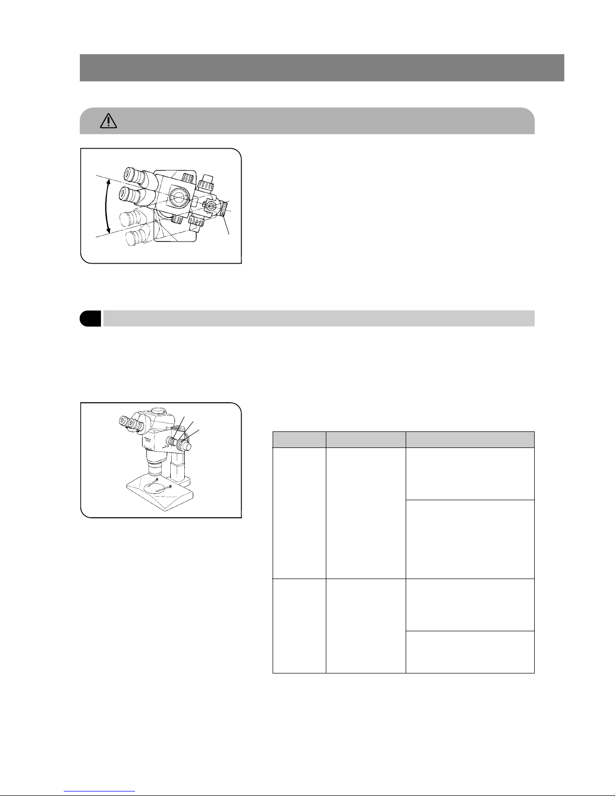
1. To prevent the microscope body from turning over, its pivot angle must
be limited to 30° as shown in Fig. 1.
2. Sufficient care is required during observation with a magnification objective, because the objective´s long working distance can displace the
microscope body to a higher position. Care is also required when using
an auxiliary pillar (SZH-P400/P600), which also makes the microscope
body unstable.
3. To adjust the microscope body height, be sure to hold the focusing assembly with one hand while loosening the focusing assembly clamping
knob @. (Fig. 1)
(Use the drop prevention collar (SZX-R) to prevent a hazard from occurring.)
<Be careful not to pinch your finger during adjustment.>
Fig. 1
1 Getting Ready
1. A microscope is a precision instrument. Handle it with care and avoid
subjecting it to sudden or severe impact.
2. Do not use the microscope where it is subjected to direct sunlight, high
temperature and humidity, or vibration. (For operating environment, see
Section 6, “Specifications” on page 16.)
3. Observe the following cautions when operating the coarse or fine focus
adjustment knobs or the zooming knob.
Fig. 2
Operation
Manipulated Controls Caution
Focusing Coarse/fine focus ad-
justment knobs @
(Fig. 2)
1. If the knob hits the upper or lower
limiting mechanism violently or
it is rotated after it hits a limiting
mechanism, the internal mechanism may be damaged.
2. If the knobs on the left and right
are rotated in opposite directions,
the internal mechanism will be
damaged. (The tension of the
coarse focus adjustment knob
should be adjusted using the
tension adjustment ring ³ on the
knob.)
Zooming Zooming knob ²
(Fig. 2)
1. If the knob hits the upper or lower
limiting mechanism violently or
it is rotated after it has hit a limiting mechanism, the internal
mechanism may be damaged.
2. If the knobs on the left and right
are rotated in opposite directions,
the internal mechanism will be
damaged.
30°
@
²
³
@

ii
4. Only one intermediate attachment can be used. Using two attachments
may obscure a part of the image. However, the vertical illuminator (SZXILLC) is not considered to be an attachment.
}When more than one intermediate attachment is to be combined, they
should be stacked according to the following order, from the bottom to
the top: SZX-ILLC, SZX-AS, SZX-RFA (SZX-RFL), SZX-SDO, SZX-APT, SZXBS, SZX-DA, SZX-FAD, then SZX-EPA.
5. The desk surface inclination with respect to the horizontal surface should
be less than 5°.
2
Maintenance and Storage
1. Clean all glass components by wiping gently with gauze. To remove fingerprints or oil smudges, wipe with gauze slightly
moistened with a mixture of ether (70%) and alcohol (30%).
Since solvents such as ether and alcohol are highly flammable, they must be handled carefully. Be sure to keep
these chemicals away from open flames or potential sources of electrical sparks -- for example, electrical equip-
ment that is being switched on or off. Also remember to always use these chemicals only in a well-ventilated
room.
2. The equipment uses plastic resins extensively in its external finish. Do not attempt to use organic solvents to clean the
non-optical components of the microscope. To clean these components, use a lint-free, soft cloth lightly moistened with a
diluted neutral detergent.
3. Never disassemble any part of the microscope as this could result in malfunctions or reduced performance.
4. When not using the microscope, keep it covered with the dust cover provided.
3
Caution
If the microscope is used in a manner not specified by this manual, the safety of the user may be imperiled. In addition,
the microscope may also be damaged. Always use the microscope as outlined in this instruction manual.
The following symbols are used to set off text in this instruction manual.
: Indicates that failure to follow the instructions in the warning could result in bodily harm to the
user and/or damage to equipment (including objects in the vicinity of the equipment).
# : Indicates that failure to follow the instructions could result in damage to equipment.
} : Indicates commentary (for ease of operation and maintenance).

CONTENTS
1 NOMENCLATURE
2 ASSEMBLY
2-1 Assembly Diagram ........................................................................................................................................................................ 2
2-2 Detailed Assembly Procedure...................................................................................................................................... 3
3 CONTROLS
4 SUMMARY OF OBSERVATION PROCEDURE
4-1 Preparation ............................................................................................................................................................................................... 7
4-2 Observation Procedure .......................................................................................................................................................... 7
5 USING THE CONTROLS
5-1 Base .................................................................................................................................................................................................................... 8
5-2 Microscope Body and Focusing Assembly.............................................................................................. 8
5-3 Observation Tube ......................................................................................................................................................................... 11
5-4 TV Observation and Photomicrography...................................................................................................... 14
6
SPECIFICATIONS
7
OPTICAL CHARACTERISTICS
8
TROUBLESHOOTING GUIDE
9
OPERATION OF OTHER ATTACHMENTS
9-1 Eyepoint Adjuster SZX-EPA............................................................................................................................................ 19
9-2 AS Unit SZX-AS (for use with the SZX-ZB9) ......................................................................................... 20
9-3 Drop Prevention Collar SZX-R and Auxiliary Pillar SZH-P400/SZH-P600 .......... 21
9-4 Revolving Nosepiece SZX-2RE .............................................................................................................................. 22
9-5 BX Stage Adapter Type 1 SZX-STAD1 .......................................................................................................... 24
9-6 BX Stage Adapter Type 2 SZX-STAD2 .......................................................................................................... 26
9-7 Stage Adapter Type 1 SZH-STAD1 ..................................................................................................................... 27
SZX
1
2
6
7
8
19
17
18
15
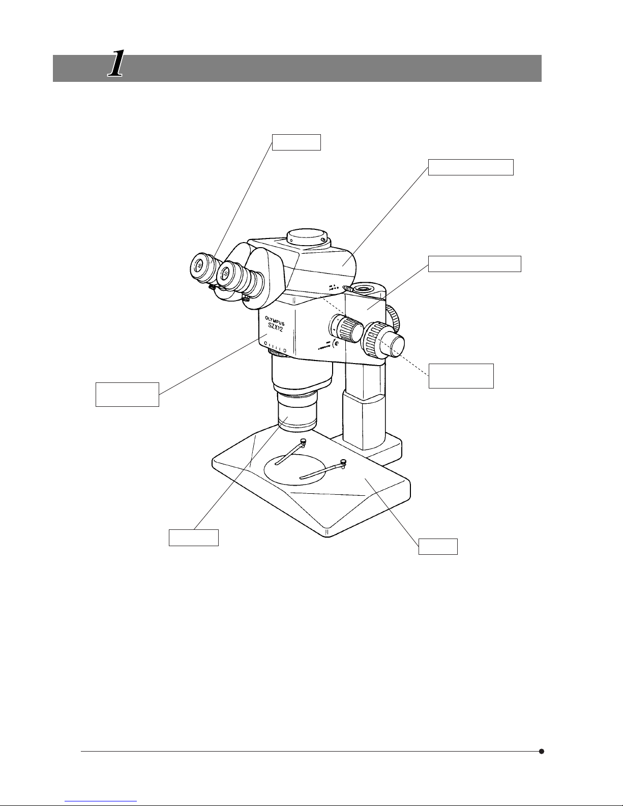
1
NOMENCLATURE
Eyepiece
· WHS10X-H
· CROSS WHS10X
· WHS15X-H
· CROSS WHS15X
· WHS20X-H
· CROSS WHS20X
· WHS30X-H
Microscope
body
· 12X zoom microscope
body: SZX-ZB12
· 9X zoom microscope
body: SZX-ZB9
Objective
þFor SZX-ZB12ý þFor SZX-ZB9ý
· DFPLFL0.3X* · DFPL0.5X-4*
· DFPLFL0.45X* · DFPL0.75X-4
· DFPLFL0.5XPF · DFPLAPO1X-4
· DFPLAPO1XPF · SZX-ACH1X
· DFPLAPO1.2XPF2 · SZX-ACH1.25X
· DFPLFL1.6XPF · DFPL1.5X-4
· SZX-AL20X · DFPL2X-4
Observation tube
· Binocular observation
tube: SZX-BI30/BI45
· Trinocular observation
tube: SZX-TR30
· Tilting binocular tube:
SZX-TBI
Focusing assembly
· Coarse/fine focus adjustment
knobs: SZX-FOF
· Focus adjustment knob:
SZX-FO
Intermediate
attachment**
· Eyepoint adjuster: SZX-EPA
· AS unit: SZX-AS
etc.
Base**
· Standard base: SZX-ST
· Large base: SZX-STL
· Transmitted light base:SZX-ILLK
SZX-ILLB2
SZX-ILLD2
* The standard base (SZX-ST) requires use of an optional auxiliary pillar (SZH-P400) and optional drop prevention collar
(SZX-R). The large base (SZX-STL) comes with the auxiliary pillar (SZH-P400) mounted as standard. This enables the large
base to be used as is. However, be sure to use the drop prevention collar (SZX-R) in combination.
** For other attachments, refer to the product catalogue.
SZX
2
ASSEMBLY
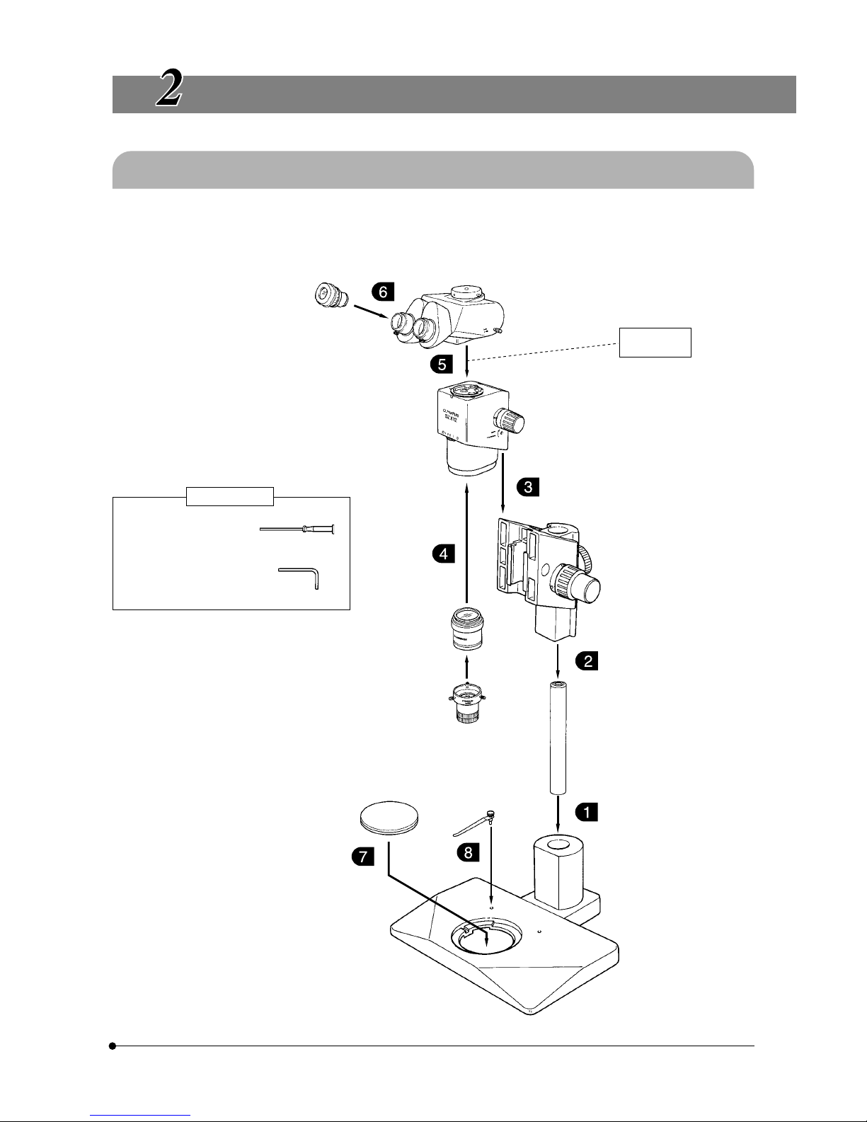
2-1 Assembly Diagram
The diagram below shows how to assemble the various modules. The numbers indicate the order of assembly.
#When assembling the microscope, make sure that all parts are free of dust and dirt, and avoid scratching any parts
or touching glass surfaces.
Allen screwdriver
(provided with the zoom
microscope body)
Allen wrench*
(provided with the standard base)
Required tools
* Do not use the Allen wrench for a purpose
other than installing the auxiliary pillar. If the
Allen wrench is used for a part other than that
described above, the force with which it is
applied may break the part.
2
Eyepiece
Observation tube
Intermediate
attachment
Zoom microscope body
Objective
Auxiliary objective
SZX-AL20X
Focusing assembly
Stage plate
Specimen
holder
Pillar
Standard base
3
2-2 Detailed Assembly Procedure
Fig. 3
Fig. 4
Fig. 5
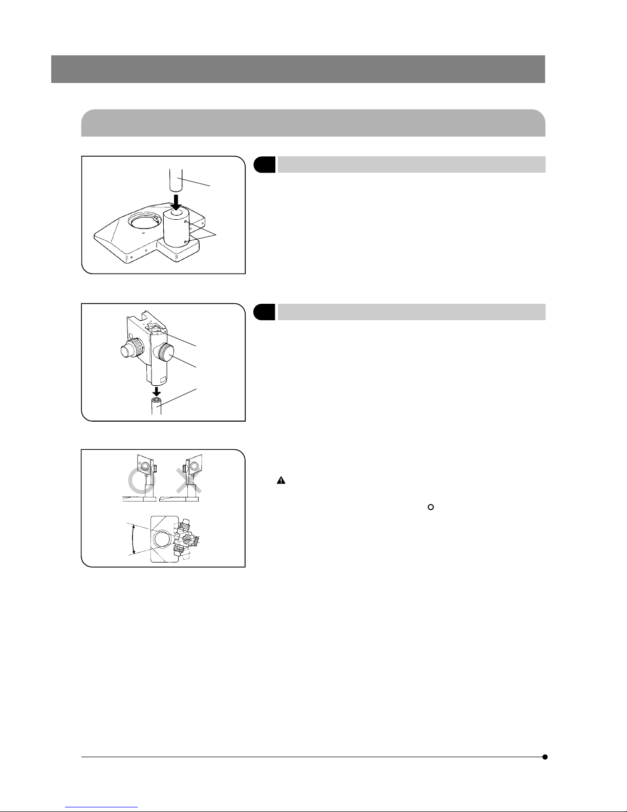
1 Installing the Pillar
(Fig. 3)
1. Using the Allen wrench provided with the base, loosen the 2 clamping
screws @ on the pillar support sleeve completely.
2. Hold the pillar ² with the white rubber cap at the top, and insert it into the
pillar support sleeve until it reaches the bottom.
3. Using the provided Allen wrench, tighten the 2 clamping screws ²
securely.
2 Mounting the Focusing Assembly
(Figs. 4 & 5)
1. First loosen the focusing assembly clamping knob @ completely, and
while holding the focusing assembly with both hands, insert the pillar ³
into the mounting hole ² from below. (Fig. 4)
#Insert slowly. Do not apply excessive force.
2. Lower the focusing assembly until it stops, then tighten the focusing
assembly clamping knob @. (Fig. 4)
To prevent the microscope from turning over, the focusing assembly
must be installed on the same side as the stage plate in the stand,
as shown in the illustration marked “ ” in Fig. 5, and its pivot angle
must be limited to 30°. If the focusing assembly is placed on the
wrong side, the microscope will turn over.
#If the clamping knob @ is tightened while the pillar ³ is not com-
pletely inserted into the mounting hole ², the plate spring supporting the pillar will deform and the pillar will not be able to penetrate
into the hole. (Fig. 4)
@
²
³
@
²
30°or less
SZX
4
Fig. 6
Fig. 7
Fig. 8
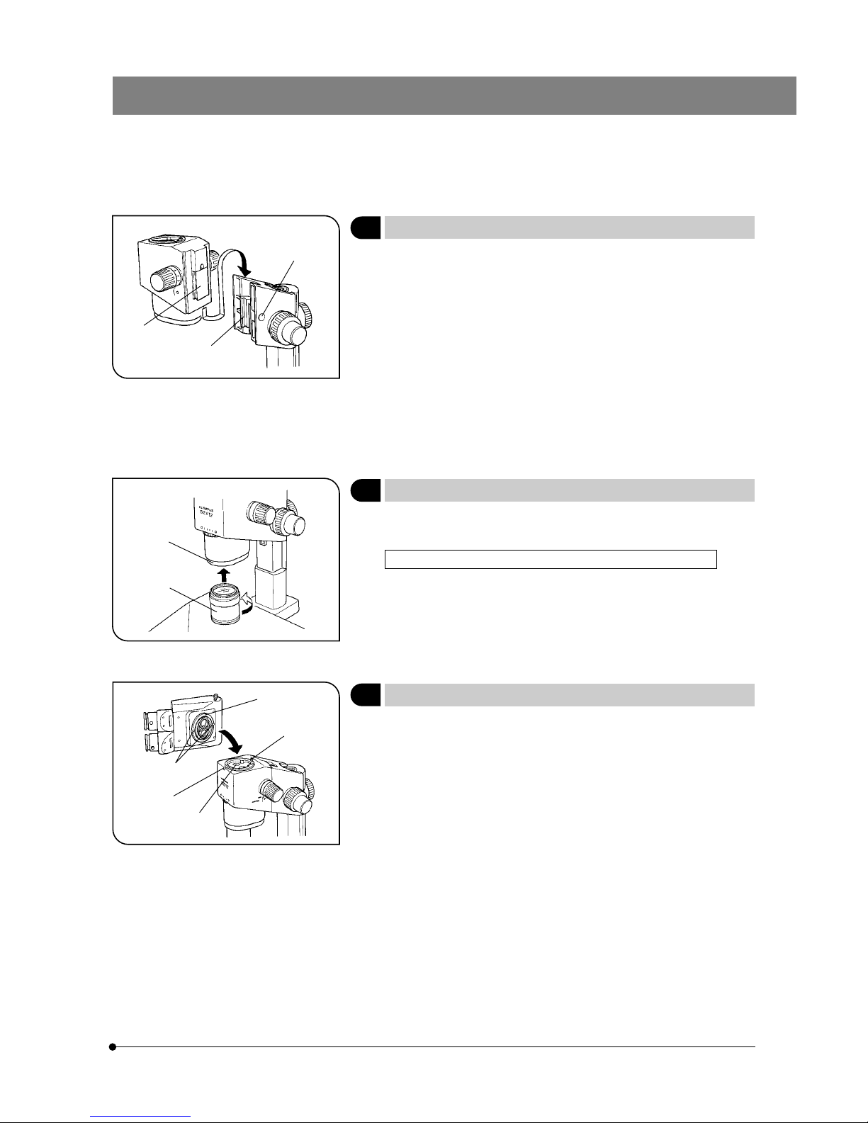
3 Mounting the Microscope Body
(Fig. 6)
1. Remove the cap @ on the focusing assembly by inserting a thin object
into the notch.
2. Using the provided Allen screwdriver, loosen the dovetail mount clamping screw inside the cap on the focusing assembly by rotating it by 2 or
3 turns (counterclockwise).
3. Gently insert the dovetail mount ³ on the rear of the microscope body
into the dovetail mounting port ² on the focusing assembly.
# Do not insert the mount at an angle or with excessive force, for this
may cause malfunctions.
4. When the microscope body has been inserted until it stops, tighten the
clamping screw using the Allen screwdriver.
5. Place the cap @ in the original position.
4 Mounting the Objective
(Fig. 7)
Mount the objective ² on the objective mount thread @ by rotating the
objective in the direction of the arrow.
Mounting the Auxiliary Objective SZX-AL20X (SZX-ZB12 only)
When using the auxiliary objective (SZX-AL20X), mount it onto the tip
of the DFPLAPO1XPF objective and tighten the clamping screw while
pushing it against the tip. (See page 10.)
Remember that the SZX-AL20X cannot be used with other objectives.
5 Mounting the Observation Tube
(Fig. 8)
1. Using the Allen screwdriver, loosen the observation tube clamping screw
@ completely.
2. Aligning the positioning pin ³ of the microscope body to the positioning
groove ² on the observation tube, insert the dovetail mount | at the
bottom of the observation tube into the mounting port ƒ on the microscope body.
3. Using the Allen screwdriver, tighten the observation tube clamping
screw @.
# The observation tube can be mounted 180° from the above posi-
tion, but this positioning makes observation difficult and is not recommended. When the auxiliary pillar is used, this positioning is impossible because the eyepiece gets in the way.
@
²
³
@
²
@
²
³
|
ƒ
5
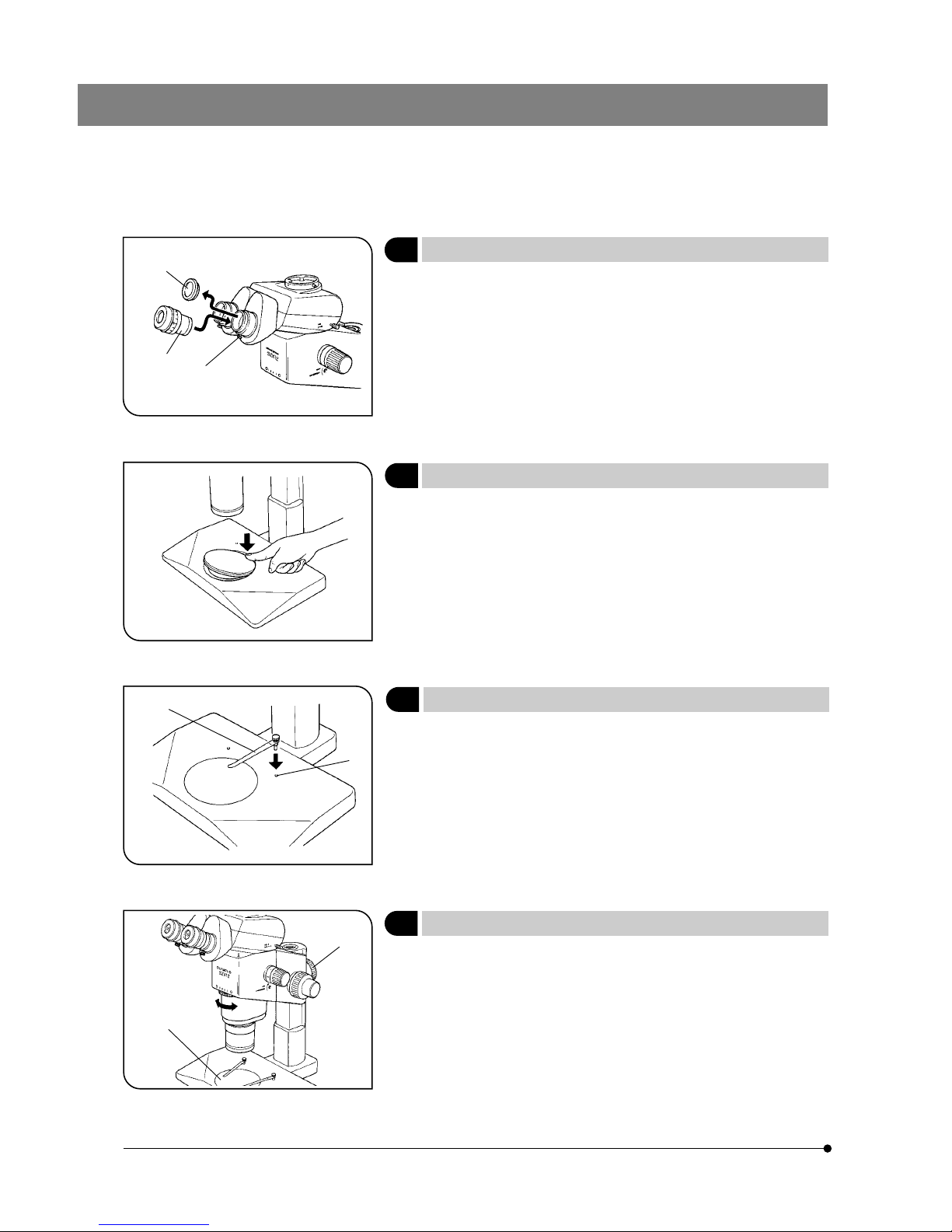
6 Mounting the Eyepiece
(Fig. 9)
1. Remove the eyepiece dust caps @ and loosen the eyepiece clamping
screws ² completely.
2. Gently insert the cross-lined eyepiece (CROSS WHS10X) ³ (if this is not
provided, use the WHS10X-H) into the right eyepiece sleeve until it stops.
3. Gently insert the eyepiece (WHS10X-H) into the left eyepiece sleeve until
it comes up against the stop.
4. Tighten both eyepiece clamping screws ².
7 Mounting (Removing) the Stage Plate
(Fig. 10)
Place the stage plate (white, black on back side) into the mounting hole
on the base.
To remove, press the stage plate at the edge nearest to the pillar with
your fingertip. The opposite end will rise from the base so the stage plate
can be picked up easily.
8 Mounting the Specimen Holder
(Fig. 11)
Insert the specimen holder @ into the 2 holes ² on the top surface of the
base.
9 Positioning the Microscope Body on the Stand
(Fig. 12)
Loosen the focusing assembly clamping knob @. Slightly pivoting the
microscope body to the left and right, align the center of the objective
with the center of the stage plate ², then clamp the microscope body
with the focusing assembly clamping knob.
Fig. 9
Fig. 10
Fig. 11
Fig. 12
@
²
³
@
²
@
²
SZX
6
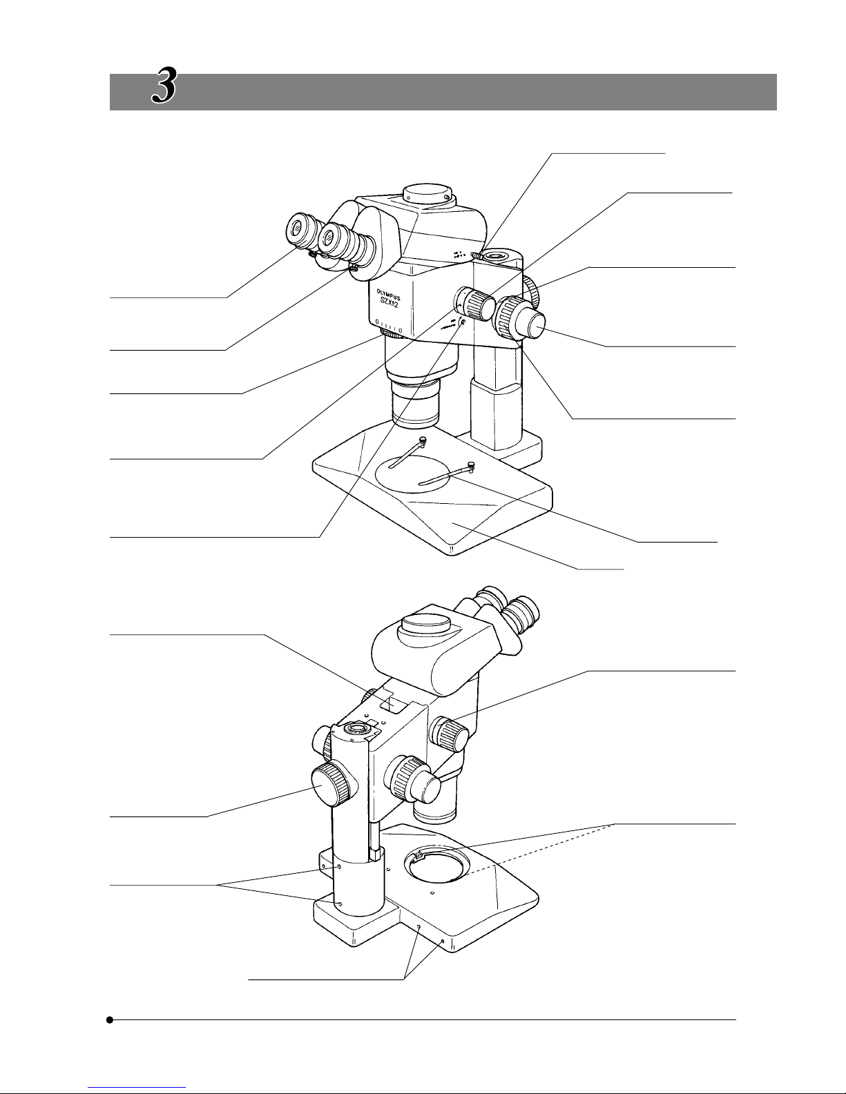
CONTROLS
Zooming knob
SZX-ZB12: 0.7X to 9X
SZX-ZB9: 0.63X to 5.7X
Diopter adjustment ring
±
5m
-1
(per meter)
Eyepiece clamping knob
Aperture iris diaphragm ring
(SZX-ZB12 only)
Observation magnification
indicator
Shows the total magnification
when the objective is 1X and eyepiece is 10X.
Click stop ON-OFF screw
Engages or disengages the click stop func-
tion for each magnification indicated on the
zooming knob.
Light guide hole
SZX-CSP/LG-DFI mounting holes
Focusing assembly
clamping knob
Pillar clamping screws
Spare screw holes
(4 mm threaded holes x 4)
Used to mount a manipulator, etc.
Light path selector knob
(SZX-TR30 only)
Coarse focus adjustment knob
Stroke: 80 mm
Stroke per turn (SZX-FOF): 36.8 mm
Stroke per turn (SZX-FO): 21.2 mm
Fine focus adjustment knob
(SZX-FOF only)
Stroke: 80 mm
Stroke per turn: 1.5 mm
Coarse focus adjustment knob
tension adjustment ring
Specimen holder
Hand rest
Magnification indicator ring
Provided with the objective
(except 1X objective).
} Can also be attached onto
the right zooming knob.
Stage adapter screw hole
(4 mm threaded x 2)
7
SUMMARY OF OBSERVATION PROCEDURE
4-1 Preparation
1. Check and tighten the connection of each component, especially the observation tube. ...................................................... (Page 4)
2. Adjust the position of the microscope body. .......................................................................................................................................................................................... (Page 5)
3. Adjust the tension of the coarse focus adjustment knob. ....................................................................................................................................................(Page 8)
4. Prepare desired illuminators.
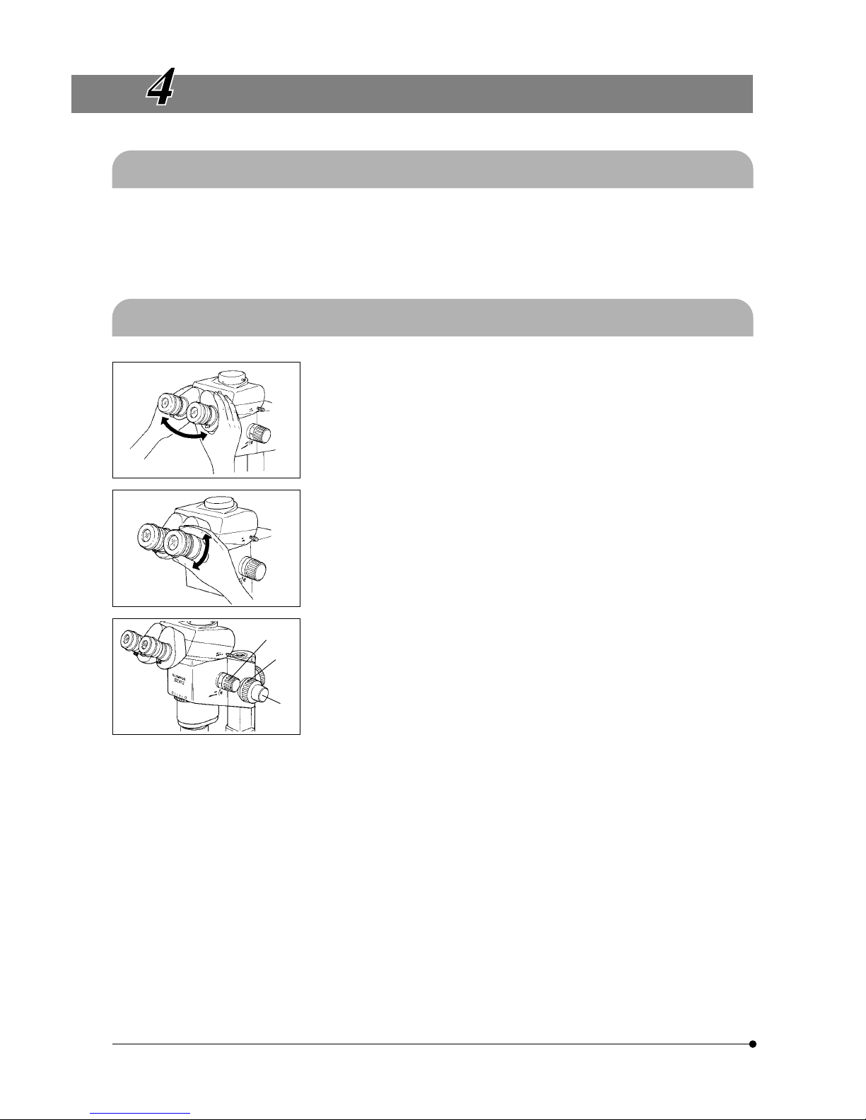
4-2 Observation Procedure
1. Place a specimen on the stage. (Page 8)
2. Adjust interpupillary distance. (Page 11)
3. Make diopter adjustment. (Page 11)
(The adjustment procedure is variable depending on whether a CROSS
eyepiece is used or not.)
4. Set the zooming knob @ to the lowest zoom magnification and bring the
microscope into focus by rotating the coarse focus adjustment knob ².
5. Rotate the zooming knob @ to the desired magnification and precisely
focus the microscope on the specimen with the coarse focus adjustment knob ² and fine focus adjustment knob ³ (the fine focus adjustment knob is not provided with the SZX-FO).
}When the SZX-ZB12 microscope body is used, the contrast of the ob-
served image and the focal depth of the specimen can be adjusted
with the built-in aperture iris diaphragm ring.
@
²
³
 Loading...