

Page 1

Modules described in this manual
SZX16
SZX-R/SZH-P400/SZH-P600
SZX-2-2RE16
SZX-STAD1
SZX2-AN
SZX-PO
SZX-STAD2
SZH-STAD1
INSTRUCTIONS
SZX16
RESEARCH HIGH-CLASS STEREO
MICROSCOPE
This instruction manual is for the Olympus SZX16 Research High-Class Stereo Microscope System.
To ensure the safety, obtain optimum performance and to familiarize yourself full with the use of this
microscope, we recommend that you study this manual thoroughly before operating the microscope.
Retain this instruction manual in an easily accessible place near the work desk for future reference.
A X 7 5 0 0
Page 2

This device complies with the requirements of directive 98/79/EC concerning in vitro diagnostic
medical devices. CE marking means the conformity to the directive.
Page 3

CONTENTS
SZX16
IMPORTANT — Be sure to read this section for safe use of the equipment. —
1 NOMENCLATURE
2 CONTROLS
3 SUMMARY OF OBSERVATION PROCEDURE
4 USING THE CONTROLS
4-1 Base ...................................................................................................................................................................................................................... 7
1 Using the Stage Plate 2 Placing the Specimen
4-2 Microscope Body and Focusing Assembly ......................................................................................... 7-9
1 Adjusting the Tension of the Coarse Focus Adjustment Knob
2 Engaging and Disengaging the Zooming Knob Click Stop Function
1-3
4
5
6
7-13
3 Adjusting the Aperture Iris Diaphragm 4 Zoom Magnification Indication
5 2X Objective Correction Collar
4-3 Observation Tube .................................................................................................................................................................. 10-12
1 Adjusting the Interpupillary Distance
2 Adjusting the Diopter (Zoom Parfocal Adjustment)
3 Using the Eye Shades 4 Using the Eyepiece Micrometer Disk
5 Selecting the Light Path 6 Adjusting the Tilt
4-4 TV Observation and Photomicrography ........................................................................................................ 13
1 Selecting the TV Adapter Magnification 2 Mounting the TV Adapter
3 Selecting the TV Camera Light Path
5 TROUBLESHOOTING GUIDE
6 SPECIFICATIONS
14
15,16
OBSERVATION MAGNIFICATIONS AND OBSERVATION AREAS
7
17
Page 4

8 ASSEMBLY
18-21
9 OPERATION OF OTHER MODULES
9-1
Drop Prevention Collar SZX-R and Auxiliary Pillar SZH-P400/SZH-P600
9-2 Revolving Nosepiece SZX2-2RE16.......................................................................................................... 23-25
9-3 BX Stage Adapter Type 1 SZX-STAD1 ................................................................................................. 26-28
9-4 BX Stage Adapter Type 2 SZX-STAD2 ................................................................................................. 29-30
9-5 Stage Adapter Type 1 SZH-STAD1 ...................................................................................................................... 30
22-30
........ 22
Page 5
SZX16
IMPORTANT
SAFETY PRECAUTIONS
1. After the equipment has been used in an observation of a specimen that is accompanied with a potential of infection,
clean the parts coming in contact with the specimen to prevent infection.
· Moving this microscope is accompanied with the risk of dropping the specimen and causing infections. Be sure to
remove the specimen before moving this product.
· In case the specimen is damaged by erroneous operation, promptly take the infection prevention measures.
· The microscope may become unstable when certain intermediate attachments and/or photography unit are mounted
on it. Take the measures so that the microscope does not turn over.
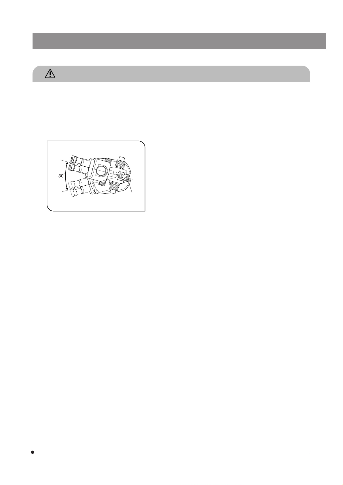
2. To prevent the microscope body from turning over, its left-right pivot angle
must be limited to 30° as shown in Fig. 1. The tilt of the desktop surface
should be no more than 5°.
3. Sufficient care is required during observation with a low-magnification
objective, because the objective’s long WD (Working Distance) can
displace the microscope body to a higher position.
The measures for prevention of turning over are also required when using
@
Fig. 1
an auxiliary pillar (SZH-P400/P600), because this also makes the
microscope body to be displaced to a higher position.
4. To adjust the microscope body height, be sure to hold the microscope
body with one hand while loosening the focusing assembly clamping
knob @. (Fig. 1)
(Use the drop prevention collar (SZX-R) to prevent a hazard from occurring.)
Be careful not to pinch your finger during the adjustment.
1
Page 6
Getting Ready
1
1. A microscope is a precision instrument. Handle it with care and avoid
subjecting it to sudden or severe impact.
2. Do not use the microscope where it is subjected to direct sunlight, high
temperature and humidity, or vibration. (For the operating environment,
see Chapter 6, “SPECIFICATIONS” on page 16.)
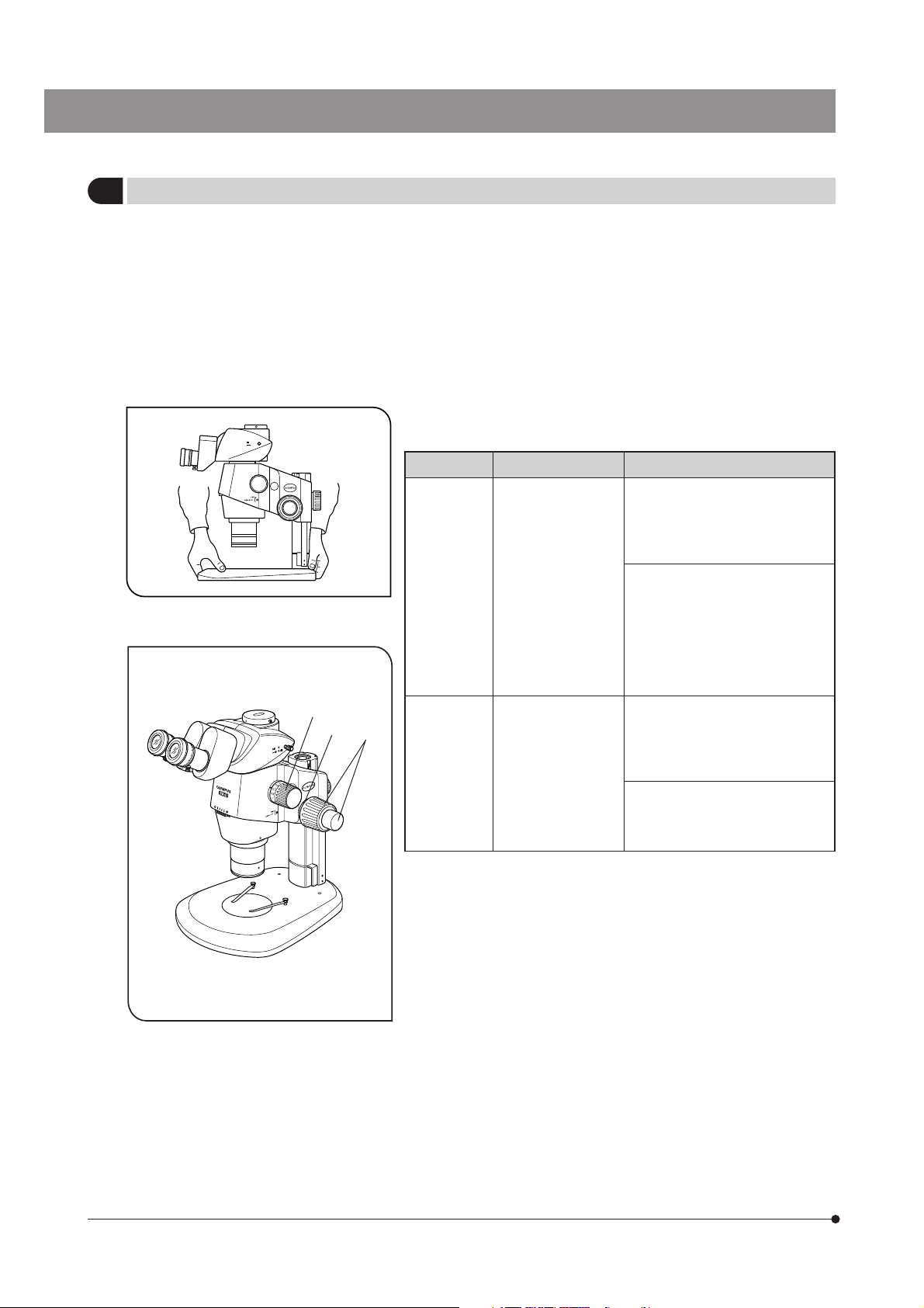
3. When moving the microscope, remove the specimen in advance. Then,
hold the front part of the base with one hand and hold the rear part of the
base with the other hand to avoid tilting the microscope.
Also remove any module or attachment from the microscope to minimize
the weight before moving.
4. Observe the following cautions when operating the coarse focus
adjustment knob or the zooming knob.
Fig. 2
²
³
Operation
Focusing Coarse/fine focus
Zooming Zooming knob ²
@
5. Only one intermediate attachment can basically be used, but two
attachments may also be used though the peripheral part of the image
may be obscured.
For the coaxial vertical illuminator (SZX2-ILLC16) and reflected fluorescent
light illuminator (SZX2-RFA16), only either can be attached because they
must always be attached at the lowest position.
}The SZX2-ILLC16 is not considered to be an attachment. Therefore, the
SZX2-LBS can be mounted above it without any restriction.
Manipulated Controls
adjustment knobs @
(Fig. 3)
(Fig. 3)
Caution
1. If the knob hits the upper or lower
limiting mechanism violently or
it is rotated after it hits a limiting
mechanism, the internal
mechanism may be damaged.
2. If the knobs on the left and right
are rotated in opposite directions,
the internal mechanism will be
damaged. (The rotation tension
of the coarse focus adjustment
knob should be adjusted using
the rotation tension adjustment
ring ³ on the knob.)
1. If the knob hits the upper or lower
limiting mechanism violently or
it is rotated after it hits a limiting
mechanism, the internal
mechanism may be damaged.
2. If the knobs on the left and right
are rotated in opposite directions,
the internal mechanism will be
damaged.
2
Fig. 3
Page 7

Maintenance and Storage
2
1. To clean the lenses and other glass components, simply blow dirty away using a commercially available blower and wipe
gently using a piece of cleaning paper (or clean gauze).
If a lens is stained with fingerprints or oil smudges, wipe it gauze slightly moistened with commercially available absolute
alcohol.
Since the absolute alcohol is highly flammable, it must be handled carefully.
Be sure to keep it away from open flames or potential sources of electrical sparks -- for example, electrical
equipment that is being switched on or off.
Also remember to always use it only in a well-ventilated room.
2. The equipment uses plastic resins extensively in its external finish. Do not attempt to use organic solvents to clean them
but simply wipe them using a lint-free, soft cloth. To clean an extremely dirty part, use a soft cloth lightly moistened with a
diluted neutral detergent.
3. Never disassemble any part of the microscope as this could result in malfunctions or reduced performance.
4. When not using the microscope, keep it covered with the dust cover provided. If a module containing a source of heat is
mounted on the microscope, wait until it has cooled down before covering.
5. This equipment should be disposed of by following the rules and regulations of your national or local government.
SZX16
Caution
3
If the microscope is used in a manner not specified by this manual, the safety of the user may be imperiled. In addition,
the microscope may also be damaged. Always use the microscope as outlined in this instruction manual.
The following symbols are used to set off text in this instruction manual.
: Indicates that failure to follow the instructions in the warning could result in bodily harm to the
user and/or damage to equipment (including objects in the vicinity of the equipment).
# : Indicates that failure to follow the instructions could result in damage to equipment.
} : Indicates commentary (for ease of operation and maintenance).
Intended use
4
This instrument has been designed to be used to observe magnified images of specimens in routine and research
applications.
Do not use this instrument for any purpose other than its intended use.
3
Page 8
NOMENCLATURE
1
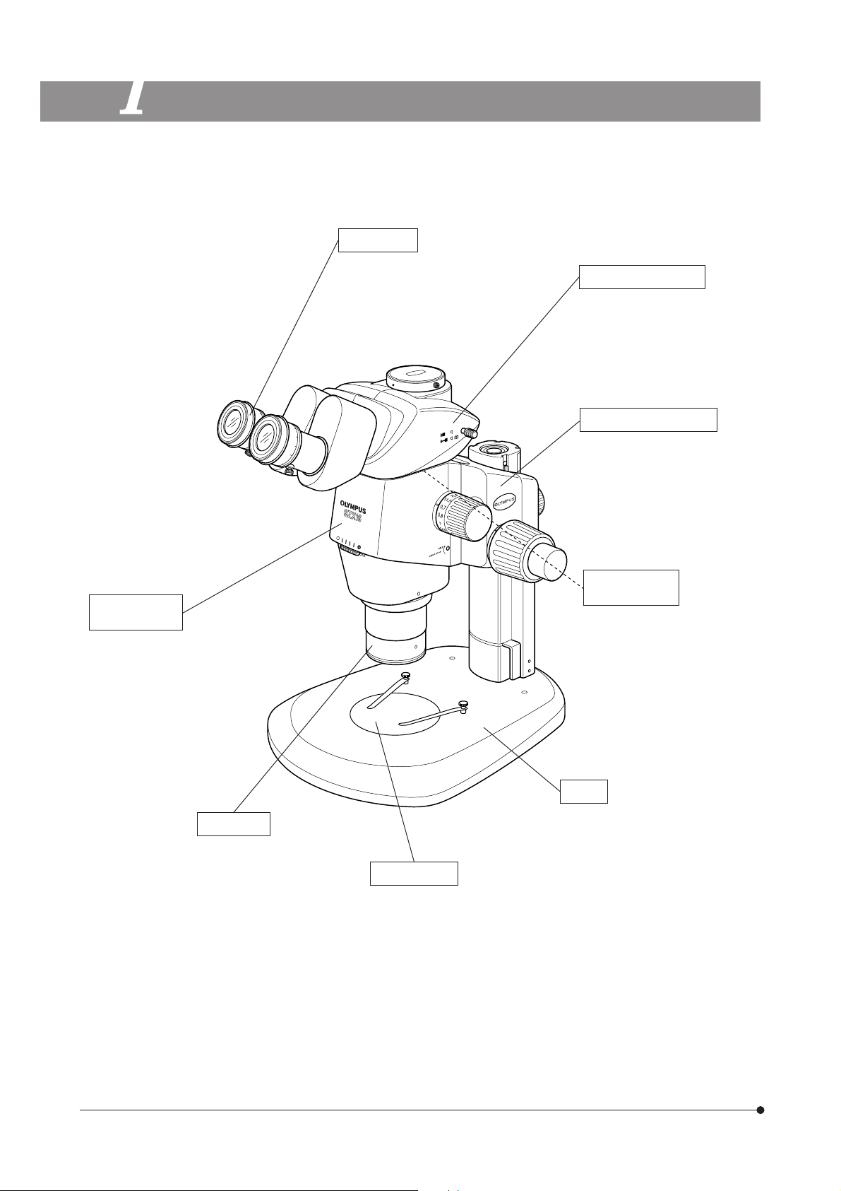
}The following illustration shows a typical system composed of modules marked with “{” in the list of each module, and
other modules may also be used in place of them. For the modules that are not shown in the module lists below, please
contact Olympus or the latest catalogues.
Eyepieces
{WHN10X-H
· WHSZ15X-H
· WHSZ20X-H
· WHSZ30X-H
Observation tube
{Trinocular observation
tube: SZX2-TR30/TR30PT
· Tilting trinocular observation
tube: SZX2-TTR/TTRPT
Focusing assembly
· Coarse/fine focusing assembly:
SZX2-FOF
· Focusing assembly: SZX2-FO
{Coarse/fine focusing assembly
for heavy load: SZX2-FOFH
· Motorized focusing assembly:
SZX2-FOA2
Intermediate
attachments
Microscope
body
{16X zoom microscope
body: SZX2-ZB16
· Coaxial vertical illuminator:
SZX2-ILLC16*
· Beam splitter: SZX2-LBS*
· Vertical fluorescent light
illuminator: SZX2-RFA16*
Base
Objective
· SDFPLFL0.3X**
· SDFPLAPO0.5XPF
· SDFPLAPO0.8X
{SDFPLAPO1XPF
· SDFPLAPO1.6XPF
· SDFPLAPO2XPFC
*A separate instruction manual is available for the module marked *.
**The standard base (SZX2-ST) requires use of the optional auxiliary pillar (SZH-P400) and optional drop prevention collar
(SZX-R). The large base (SZX2-STL) comes with the auxiliary pillar (SZH-P400) mounted as standard. This enables the
large base to be used as is. However, be sure to use the drop prevention collar (SZX-R) in combination.
Stage plate
{Monochrome plate: SZ2-SPBW/SP-BW2
· Glass plate: SP-C
· Fluorescence center plate: SP-FL
{Standard base: SZX2-ST**
· Large base: SZX2-STL
· Transmitted light base: SZX2-ILLB*
SZX2-ILLD*
SZX2-ILLK*
SZX2-ILLT*
4
Page 9
CONTROLS
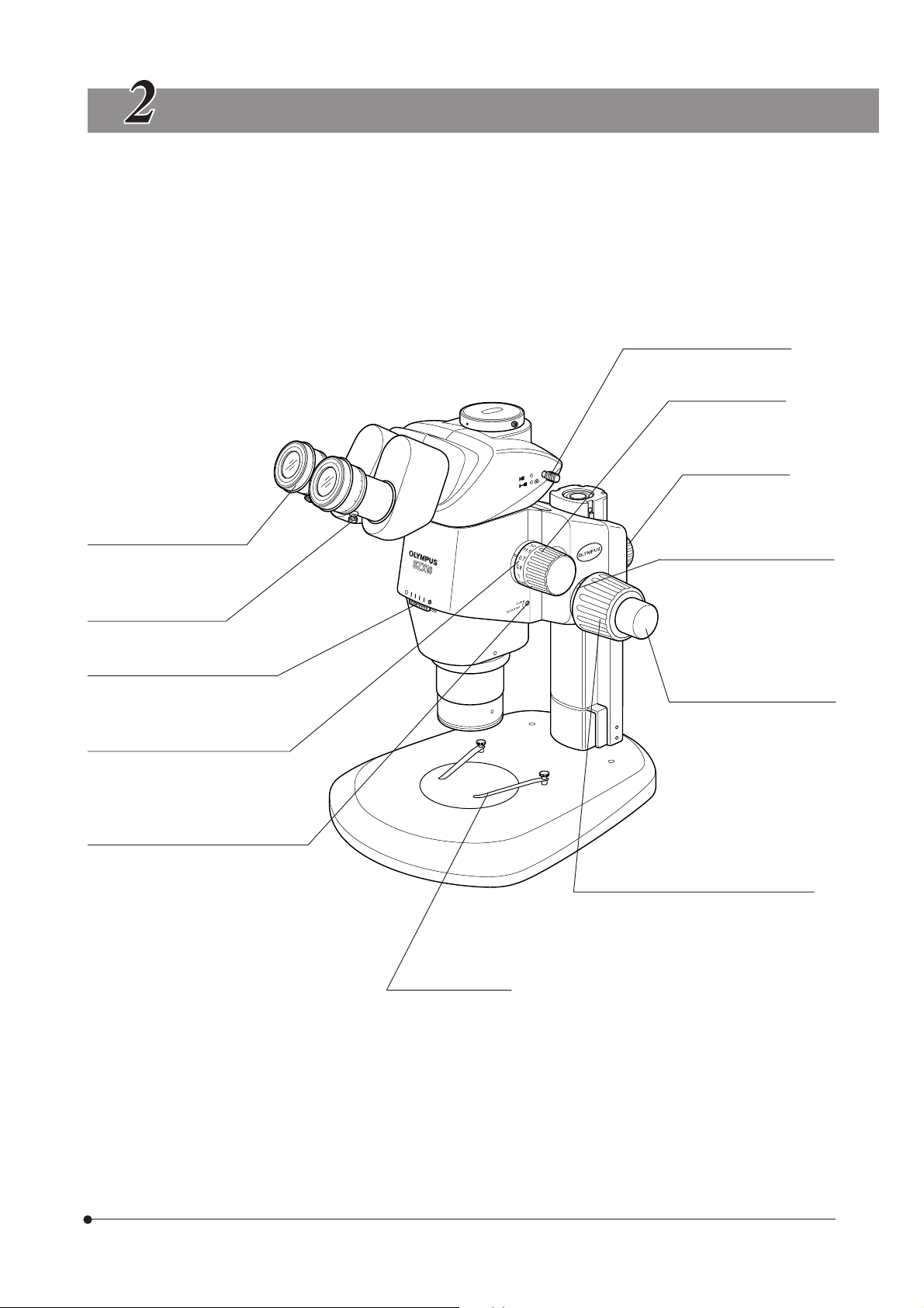
}If the microscope is not yet assembled, see Chapter 8, “ASSEMBLY” (pages 18 to 21) before the following.
Light path selector knob (P. 12)
Zooming knob
0.7X to 11.5X
Focusing assembly
clamping knob
SZX16
Diopter adjustment ring (P.10)
±
5m-1 (per meter)
Eyepiece clamping knob
Aperture iris diaphragm ring (P. 8)
Zoom magnification indication (P. 9)
0.7 to 11.5 (14 indications)
Click stop ON-OFF screw (P. 8)
Engages or disengages the click stop
function for each zoom magnification.
Coarse focus adjustment knob
tension adjustment ring (P. 7)
Fine focus adjustment knob
(SZX2-FOF/FOFH)
Stroke: 80 mm
Stroke per turn: 0.77 mm
Coarse focus adjustment knob
Total Stroke: 80 mm
Stroke per turn (SZX2-FOF/FOFH): 36.8 mm
Stroke per turn (SZX2-FO): 21 mm
Specimen holder
Locks the specimen.
5
Page 10
SUMMARY OF OBSERVATION PROCEDURE
3-1 Preparation
Ref. Page
1. Check and tighten the connection of each component, especially the observation tube................................................... (Page 20)
2. Check that the angled formed by the microscope body with respect to the base is less than the
turning-over prevention angle. .................................................................................................................................................................................................................................(Page 19)
3. Adjust the tension of the coarse focus adjustment knob. ..................................................................................................................................................(Page 7)
4. Confirm the correct settings.
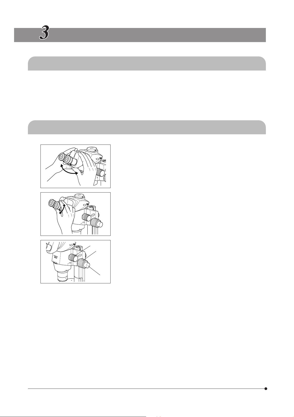
3-2 Observation Procedure
1. Place a specimen on the stage. (Page 7)
2. Adjust the interpupillary distance. (Page 10)
3. Make diopter adjustment of the eyepieces. (Page 10)
@
²
³
(The adjustment procedure is variable depending on whether the eyepiece
micrometer disk is used or not.)
4. Set the zooming knob @ to the lowest zoom magnification and bring the
microscope into focus by rotating the coarse focus adjustment knob ².
5. Rotate the zooming knob @ to the desired magnification and precisely
focus the microscope on the specimen with the coarse focus adjustment
knob ² and fine focus adjustment knob ³ (the fine focus adjustment
knob is not provided with the SZX2-FO).
}The contrast of the observed image and the focal depth of the specimen
can be adjusted with the aperture iris diaphragm ring.
6
Page 11
USING THE CONTROLS
4-1 Base
1 Using the Stage Plate
In reflected light observation, the stage plate can be placed either the
white or black side facing up.
#Win transmitted light observation, use the transparent glass stage
plate (SP-C).
Placing the Specimen
2
1. Place the specimen on the approximate center of the stage plate. Hold
the specimen with the specimen holder as required.
2. Illuminate the specimen with an illuminator selected according to the
specimen under observation.
SZX16
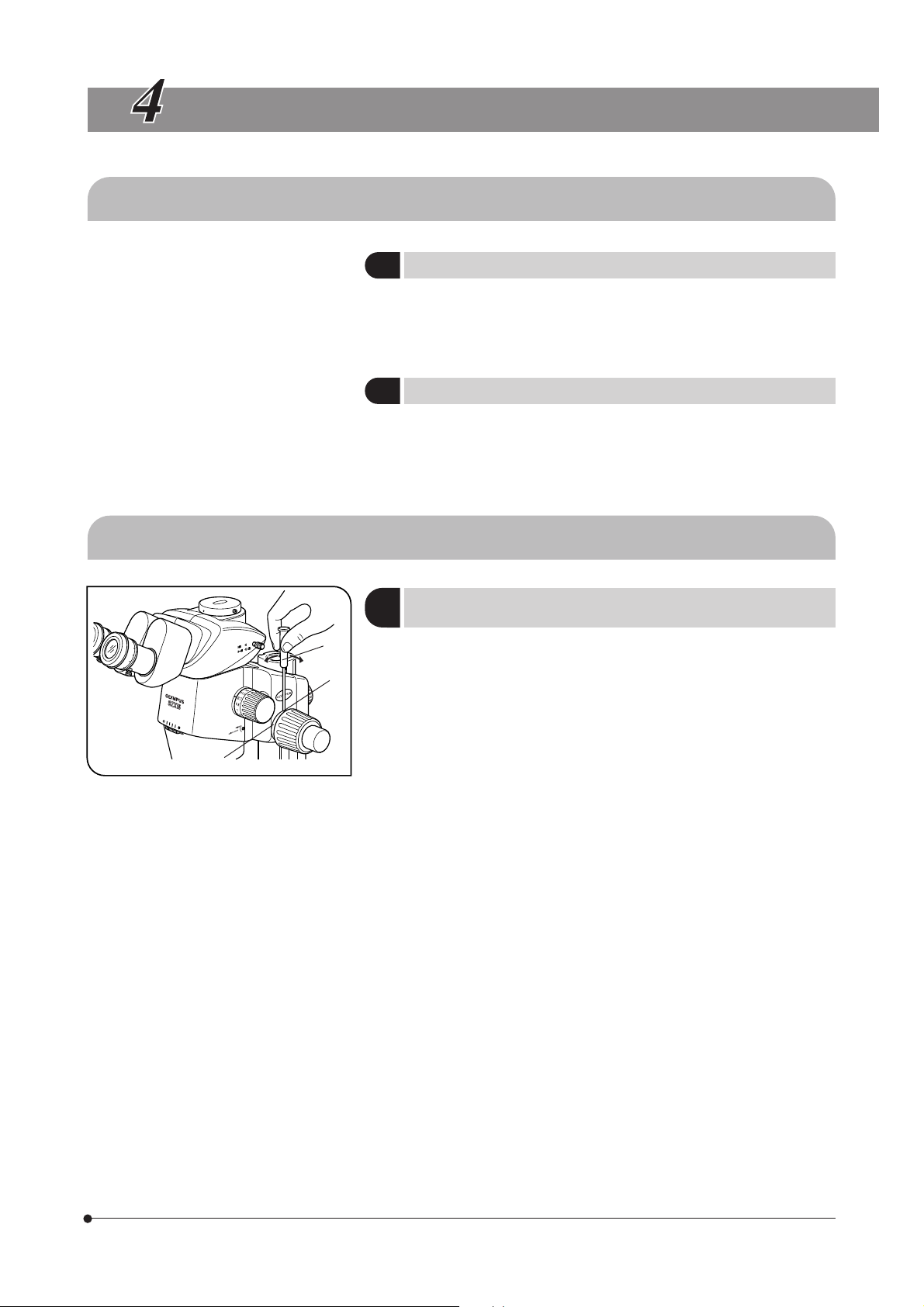
4-2 Microscope Body and Focusing Assembly
Adjusting the Tension of the Coarse
1
Focus Adjustment Knob
³
²
@
Fig. 4
}This operation is intended to facilitate the rotation of the knobs while
preventing the spontaneous drop of the microscope body. It is
recommended to set the knob tension to a slightly higher level than the
point where spontaneous drop occurs.
If the knobs are hard to move because of the weight of option modules
and/or TV camera mounted on the microscope body, it is recommended
to use the focusing assembly for heavy load (SZX2-FOFH).
#The tension of the coarse focus adjustment knob can be adjusted
with the tension adjustment ring @. Do not rotate the knobs on the
left and right in opposite directions, for this will damage the internal
mechanism.
1. Rotate the tension adjustment ring @ by inserting the Allen screwdriver
³ into the hole ² on the ring periphery.
Rotating the ring clockwise increases the tension of the coarse focus
adjustment knob, and rotating counterclockwise decreases it.
#If the microscope body falls down by its own weight or the focus
obtained by fine focusing is lost immediately, the tension adjustment
may be too light. In this case, rotate the ring clockwise to increase
the tension.
#If the tension adjustment is too tight, delicate focusing will be
impossible and the knob may be damaged. Particularly, to prevent
damage, never rotate the fine focus adjustment knob quickly while
its tension is extremely tight.
(Fig. 4)
7
Page 12

²
@
Fig. 5
Engaging and Disengaging the Zooming
2
Knob Click Stop Function
}When the click stop knob is set to ON, the click stop function is engaged
for each magnification indicated with the zooming knob. When the knob
is set to OFF, the zoom magnification can be varied continuously and
finely near the click groove.
The click stop knob has been set to OFF before the microscope is shipped
from the factory.
}A click stop is provided for each of the 12 intermediate indication positions
of the zoom microscope body.
1. To engage the click stop function, rotate the click stop ON-OFF screw @
fully clockwise (in the direction of the arrow) using the Allen screwdriver.
The zooming knob then stops at every position corresponding to the
magnification indicated on the zoom magnification indication ².
2. To disengage the click stop function, rotate the click stop ON-OFF screw
@ fully by three turns from the ON position, in the direction opposite to
the arrow, using the Allen screwdriver.
#Do not rotate the screw too much, or the cover may be damaged.
(Fig. 5)
@
Fig. 6
Adjusting the Aperture Iris Diaphragm
3
}Adjusting the aperture iris diaphragm increases the contrast of the
observed image as well as the depth of focus.
However, setting the aperture iris diaphragm too narrowly degrades
resolution.
1. Adjust the aperture iris diaphragm ring @ to the left or right.
Rotating the ring toward the left (\) opens the aperture; rotating it toward
the right ( ) closes it. Adjust while monitoring the observed image to
confirm the contrast and focal depth improvement effects.
#Do not close the aperture too much, for this may cause degradation
in resolution and/or lack of ambient light.
2. Use the scale gradations as references for memorizing the ring position.
#When the microscope is combined with the coaxial vertical illuminator
(SZX2-ILLC16), minimizing the aperture may obscure a part of the
observed field of view. In this case, open the aperture to an intermediate
position.
(Fig. 6)
8
Page 13

SZX16
@
@
Water
depth:
5 mm
or less
Fig. 7
Fig. 8
Zoom Magnification Indication
4
The body zoom magnification is indicated on the zooming knob on the
right side.
The total magnification of observation can be calculated with the following
formula:
Objective
magnification magnification magnification
2X Objective Collection Collar
5
}The SDFPLAPO2XPFC objective is provided with a correction collar @ for
use in compensating for the aberration caused due to the observation
medium such as water and plastic container.
When observing a specimen in a liquid or through a petri dish cover, turn
the collar to obtain the optimum contrast.
· Correction is possible for aberration corresponding to water depth of
about 5 mm.
· The correction effect may be less tangible when the zoom magnification
is low or the aperture iris diaphragm is stopped down.
}When using the SZX2-2RE16 revolving nosepiece, hold the objective
during rotation of the ring so that the revolving nosepiece is not deviated
the click position.
Body zoom
x
Eyepiece
x
(Fig. 7)
(Fig. 8)
9
Page 14

4-3 Observation Tube
|
²
@
@
Fig. 9
Fig. 10
³
Adjusting the Interpupillary Distance
1
#Be sure to hold the binocular assembly @ with both hands to make
this adjustment.
To prevent damaging the mechanism, do not apply an excessive
force beyond the stop position.
While looking through the eyepieces, hold the left and right of the binocular
assembly @ and adjust the eyepieces by opening or closing them for
binocular vision until the left and right fields of view coincide completely.
Adjusting the Diopter
2
(Zoom Parfocal Adjustment)
}Ensure that the eyepiece clamping knob @ is tightened before starting
the adjustment.
Adjusting the diopter specific to the two eyes of each observer allows the
parfocality to be ensured across zoom magnifications.
When Not Using the Eyepiece Micrometer Disk
1. Look into the right eyepiece and rotate its diopter adjustment ring ² so
that the peripheral part of the visual field looks sharply.
2. Place an easy-to-observe specimen on the stage plate.
3. Rotate the zooming knob ³ to a low magnification and, looking only into
the right eyepiece, focus the specimen using the coarse and fine focus
adjustment knobs.
4. Rotate the zooming knob ³ to the highest magnification and, looking
only into the right eyepiece, focus the specimen using the coarse and
fine focus adjustment knobs.
5. Rotate the zooming knob ³ to the lowest magnification, look only into
the left eyepiece, and focus the specimen by rotating the left diopter
adjustment ring | instead of the coarse and fine focus adjustment knobs.
(Fig. 10)
(Fig. 9)
10
When Using the Eyepiece Micrometer Disk
1. Look into the right eyepiece that includes the eyepiece micrometer disk,
and focus the micrometer disk by rotating the diopter adjustment ring ².
2. Place an easy-to-observe specimen on the stage plate.
3. Rotate the zooming knob ³ to the highest magnification and, looking
only into the right eyepiece, focus the specimen using the coarse and
fine focus adjustment knobs.
Ensure that both the eyepiece micrometer disk and specimen are focused
accurately.
4. Rotate the zooming knob ³ to the lowest magnification, , look only into
the left eyepiece, and focus the specimen by rotating the left diopter
adjustment ring | instead of the coarse and fine focus adjustment knobs.
}Note (or memorize) the diopter readings of the left and right eyepiece
scales so that they can be duplicated quickly in the next observation.
Page 15

SZX16
Fig. 11
Fig. 12
²
@
WHN10X
Using the Eye Shades
3
When Wearing Eyeglasses
Use with eye shades in their normal folded-down position. (This will prevent
eyeglasses from being scratched by the eyepiece.)
When Not Wearing Eyeglasses
Extend the folded eyeshades in the direction of the arrow. This makes
observation easier by preventing the inverse incidence of light from
between the eyepiece and your eyes.
Using the Eyepiece Micrometer Disk
4
}A variety of eyepiece micrometer disks can be inserted into the WHN10X-
H, WHSZ15X-H and WHSZ20X-H eyepieces.
1. Unscrew the ring @ by turning it counterclockwise to remove it from the
bottom of the eyepiece.
2. Clean the eyepiece micrometer disk ² ( 24 mm, thickness 1.5 mm) to
remove dust and dirt, then place the disk into the ring @ so that the side
with reticule faces downward.
3. Attach the ring @ with the eyepiece micrometer disk ² by gently screwing
it onto the eyepiece.
#The WHSZ20X-H eyepiece is designed to apply a magnification to
the focusing plane of the micrometer disk.
As the magnification coefficient is 1.35, be sure to perform magnification
compensation when using this eyepiece in measurement.
When the micrometer disk is engaged in their light path, the light
path length will extend and the diopter scale may deviate toward
the + direction from the normal indication. However, this does not
pose any problem in actual observation.
}When the eyepiece micrometer disk is not used, wrap it in a clean sheet
of soft paper before storage.
(Fig. 11)
(Fig. 12)
11
Page 16

@
Selecting the Light Path
5
}Pull out the light path selector knob @ to set the light path for the right
eyepiece to the TV/photomicrography light path.
(The following table shows the intensity ratio of each light path in %.)
Light Path Selector Knob Pushed-in Pulled-out
SZX2-TR30
SZX2-TTR
Right Binocular 100% Binocular 50%,
TV/photo 50%
(Fig. 13)
Fig. 13
Fig. 14
( )
SZX2-TR30PT
SZX2-TTRPT
( )
#Always push or pull the light path selector knob @ all the way into a
stop position. Do not attempt to force the knob past the stop position.
Applying excessive force could destroy the mechanism.
Adjusting the Tilt
6
}Adjust the height and tilt of the observation tube to the most comfortable
viewing position.
Holding the binocular assembly with both hands, raise or lower it to the
desired position.
#Do not attempt to force the binocular assembly past the upper or
lower stop position. Applying excessive force could destroy the
mechanism.
Left Binocular 50%
Right Binocular 100% TV/photo 100%
Left
Binocular 100%
(Fig. 14)
12
Page 17

4-4 TV Observation and Photomicrography
A TV camera and/or digital camera unit can be mounted on the straight tube mount of the trinocular tube by means of
the TV adapter and/or camera mount adapter*.
* The camera mount adapter is not necessary if a TV adapter equipped with a camera mount is used.
For details, please also read the instruction manuals for the TV adapter and digital camera.
Selecting the TV Adapter Magnification
1
Set the magnification of the TV adapter according to the size of the CCD in the TV camera or digital camera.
(Example) The following figures show the TV observation/photomicrography areas when the WHN10X eyepieces with FN
22 are used.
SZX16
1 in. CCD
2/3 in. CCD
1/2 in. CCD
WHN10X
FN 22
When the 0.5X TV adapter is used When the 1X TV adapter is used
Mounting the TV Adapter
2
1. Using the Allen screwdriver, fully loosen the straight tube clamping screw
@ of the straight tube mount on the top of the trinocular tube.
2. Fit the round dovetail ² of the TV adapter into the straight tube mount of
the trinocular tube, and tighten the clamping screw @.
3. Mount the TV camera on the TV adapter. A camera mount adapter may
be required with certain TV adapters.
Selecting the TV Camera Light Path
3
Pull out the light path selector knob ³ to select the Binocular 50%/TV &
Photo 50% light path setting for the SZX2-TR30/TTR or the TV & Photo
100% light path setting for the SZX2-TR30PT/TTRPT.
²
@
³
Fig. 15
(Fig. 15)
(Fig. 15)
13
Page 18

TROUBLESHOOTING GUIDE
Under certain conditions, performance of this unit may be adversely affected by factors other than defects. If a problem
occurs, please review the following list and take remedial action as needed. If you cannot solve the problem after
checking the entire list, contact Olympus.
Problem Cause Remedy Page
1. The left and right fields of view
do not coincide.
2. The field of view is obscured
partially or illuminated
unevenly.
3. The monitor image is cut off
partially.
4. Dirt or dust is visible in the field
of view.
5. Details of observed image are
solid.
6. Visibility of observed image is
poor.
· Image is not sharp.
· Contrast is insufficient.
7. Zooming causes defocusing
of the observed image.
The interpupillary distance is adjusted
improperly.
The diopter is adjusted incorrectly. Adjust it correctly. 10
The left and right eyepieces are different. Use a pair of matched eyepieces. 21
The aperture iris diaphragm is stopped
down excessively.
The trinocular observation tube and/or
intermediate attachments are installed
improperly.
The light path selector knob is in an intermediate position.
The light path selector knob is pulled out
incompletely.
Dirt/dust on the specimen.
Dirt/dust on eyepiece.
The aperture iris diaphragm is stopped
down excessively.
The objective is tilted. Screw it correctly until it stops.
The objective is dirty. Clean thoroughly.
The top and/or bottom lenses of the microscope body are dirty.
The bottom lens of the observation tube
is dirty.
The eyepiece diopter is adjusted improperly. Adjust it correctly.
The focus adjustment is in accurate. Adjust focus at a high magnification.
Adjust it correctly.
Open the aperture iris diaphragm.
Mount them properly.
Set it correctly to the desired position.
Pull it out all the way.
Clean thoroughly.
Clean thoroughly.
Open the aperture to a proper diameter.
10
20
12
12
20
10
10
8
3
3
8
3
14
8. The coarse focus adjustment
knob does not rotate smoothly.
9. The microscope body drops
spontaneously, causing the
focusing to be deviated during
observation.
The rotation tension of the knob is set
too high.
The rotation tension of the coarse focus
adjustment knob is set too low.
The microscope body dropped spontaneously
because the weight exceeded 10 kg.
Decrease the rotation tension to an optimum level.
Increase the rotation tension to an optimum level.
Use a focusing assembly withstanding
heavy loads. (SZX2-FOF: 2.7 to 15 kg. SZX2FOFH: 8 to 25 kg.)
7
7
15
Page 19

SPECIFICATIONS
Item Specifications
SZX16
1. Zoom microscope body
· SZX2-ZB16
2. Focusing assembly
· SZX2-FOFH
· SZX2-FOF
· SZX2-FO
Left/right zoom magnification system.
Zoom drive system: Horizontal knob.
Click stop ON-OFF switchable per zoom magnification.
Zoom ratio: 16.4 (0.7X to 11.5X)
Magnification indications: 14 indications. 0.7, 0.8, 1, 1.25, 1.6, 2, 2.5, 3.2, 4, 5, 6.3, 8, 10,
11.5.
Objective mount: Threaded mount
Built-in aperture iris diaphragm.
SZX2-FOFH SZX2-FOF SZX2-FO
Focusing system: Rack & pinion roller guide
(with coarse focus adjustment knob tension adjustment ring).
Built-in gas spring counter
balance.
Coaxial coarse/fine focus
adjustment knobs.
Coarse focus adjustment knob stroke: 80 mm
Coarse knob stroke per turn: 36.8 mm
Fine focus adjustment knob stroke: 80 mm
Fine knob stroke per turn: 0.77 mm
Load: 8 to 25 kg
Built-in counter balance.
Coaxial coarse/fine focus
adjustment knobs.
Load: 2.7 to 15 kg Max. load: 10 kg
Coarse focus adjustment
knob only.
Coarse knob stroke per turn
: 21 mm
–––
–––
3. Observation tube
· SZX2-TR30
· SZX2-TR30PT
· SZX2-TTR
· SZX2-TTRPT
4. Standard base
· SZX2-ST
5. Large base
· SZX2-STL
SZX2-TR30 SZX2-TR30PT SZX2-TTR SZX2-TTRPT
Trinocular observation tube. Tilting binocular observation tube
Tube inclination: 30° Tube inclination: 5° to 45°
Light path selection:
2 steps.
(Bi 100%, Bi 50% +
TV/photo 50%)
Interpupillary distance adjustment: 51 to 76 mm.
Eyepiece clamping knobs provided.
Eyepieces: WHN10X-H, WHSZ15X-H/20X-H/30X-H
Pillar support sleeve height: 270 mm.
Base dimensions: 284(W) x 335(D) x 31(H) mm.
Specimen holder attachable.
With stage adapter mounting holes.
Pillar height: 400 mm.
Base dimensions: 400(W) x 350(D) x 28(H) mm.
Specimen holder attachable.
With stage adapter mounting holes.
Drop prevention collar: Optional SZX-R.
Light path selection:
2 steps.
(Bi 100%, TV/photo
100%)
Light path selection:
2 steps.
(Bi 100%, Bi 50% +
TV/photo 50%)
Light path selection:
2 steps.
(Bi 100%, TV/photo
100%)
15
Page 20

Item Specifications
6. Objectives
WD: Working distance
PF: Parfocal lens
* Auxiliary pillar is required when the
SZX2-ST is used.
7. Eyepieces
** 24 mm dia., 15 mm thick eyepiece
micrometer disk can be inserted.
(Note) The micrometer area outside the
FN is invisible.
SDFPLFL0.3X WD 141 mm*
SDFPLAPO0.5XPF WD 70.5 mm
SDFPLAPO0.8X WD 81 mm
SDFPLAPO1XPF WD 60 mm
SDFPLAPO1.6XPF WD 30 mm
SDFPLAPO2XPFC WD 20 mm
**WHN10X-H FN 22, diopter adjustment ring provided.
**WHSZ15X-H FN 16, diopter adjustment ring provided.
**WHSZ20X-H FN 12.5, diopter adjustment ring provided.
WHSZ30X-H FN 7, diopter adjustment ring provided.
8. Operating environment
· Indoor use.
· Altitude: Max. 2,000 m.
· Ambient temperature: 5°C to 40°C. (41°F to 104°F)
· Maximum relative humidity 80% for temperatures up to 31°C (88°F), decreasing
linearly through 70% (at 34°C), 60% (at 37°C) to 50% (at 40°C).
16
Page 21

OBSERVATION MAGNIFICATIONS AND OBSERVATION AREAS
· Observation magnification = Objective magnification x Zoom magnification x Eyepiece magnification
· Observation area = Eyepiece FN / (Objective magnification x Zoom magnification) (mm)
Eyepieces
Objective
SDFPLFL0.3X
SDFPLAPO0.5XPF
SDFPLAPO0.8X
SDFPLAPO1XPF
SDFPLAPO1.6XPF
SDFPLAPO2XPFC
* Part of the peripheral areas in the field cut off at low magnifications.
WHN10X-H WHSZ15X-H WHSZ20X-H WHSZ30X-H
FN 22 FN 16 FN 12.5 FN 7
Obs. Mag. Obs. Area Obs. Mag. Obs. Area Obs. Mag. Obs. Area Obs. Mag. Obs. Area
2.1X 104.8 3.15X 76.2 4.2X 59.5 6.3X 33.3
--- 34.5X --- 6.4 --- 51.75X --- 4.6 --- 69X --- 3.6 --- 103.5X --- 2.0
3.5X 62.9 5.25X 45.7 7X 35.7 10.5X 20.0
--- 57.5X --- 3.8 --- 86.25X --- 2.8 --- 115X --- 2.2 --- 172.5X --- 1.2
5.6X 39.3 8.4X 28.6 11.2X 22.3 16.8X 12.5
--- 92X --- 2 .4 --- 138X --- 1.7 --- 184X --- 1.4 --- 276X --- 0.8
7X 31.4 10.5X 22.9 14X 17.9 21X 10.0
--- 115X --- 1.9 --- 172.5X --- 1.4 --- 230X --- 1.1 --- 345X --- 0.6
11.2X 19.6* 16.8X 14.3 22.4X 11.2 33.6X 6.3
--- 184X --- 1.2 --- 276X --- 0.9 --- 368X --- 0.7 --- 552X --- 0.4
14X 15.7* 21X 11.4* 28X 8.9 42X 5.0
--- 230X --- 1.0 --- 345X --- 0.7 --- 460X --- 0.5 --- 690X --- 0.3
SZX16
17
Page 22

ASSEMBLY
8-1 Assembly Diagram
The diagram below shows how to assemble the various modules. The numbers indicate the order of assembly.
#When assembling the microscope, make sure that all parts are free of dust and dirt, and avoid scratching any
part.
Eyepieces
WHN10X-H
WHSZ15X-H/20X-H/30X-H
Observation tube
SZX2-TR30/TR30PT
SZX2-TTR/TTRPT
Intermediate
attachment
SZX2-ILLC16
SZX2-LBS
SZX2-RFA16
Zoom microscope body
SZX2-ZB16
Required tools
Allen screwdriver*
(provided with the zoom
microscope body)
Allen wrench**
(provided with the standard
base and focusing assembly)
* The Allen screwdriver can be stored in the
pillar.
**Do not use the Allen wrench for a purpose
other than installing the pillar and the zoom
microscope body.
Objective
SDFPL series
Stage plate
Specimen
holder
S-CL
Focusing assembly
SZX2-FOF
SZX2-FO
SZX2-FOFH
2
Allen screwdriver storage hole**
Pillar
(Provided with the SZX2-ST)
18
Standard base
SZX2-ST
Page 23

8-2 Detailed Assembly Procedure
SZX16
³
Fig. 16
Fig. 17
@
²
³
²
@
Installing the Pillar
1
1. Using the Allen wrench provided with the base, loosen the two clamping
screws @ on the pillar support sleeve completely.
2. Hold the pillar ² so that the Allen screwdriver storage hole comes cap at
the top, and insert the pillar into the pillar support sleeve until it reaches
the bottom.
3. Using the provided Allen wrench, tighten the two clamping screws @
securely.
Reserve Screw Holes
Two screw holes ³ (6 mm) are provided for use in mounting a manipulator,
etc.
Mounting the Focusing Assembly
2
1. First loosen the focusing assembly clamping knob @ completely and,
while holding the focusing assembly with both hands, insert the pillar ³
into the mounting hole ² from below. (Fig. 17)
#Insert slowly. Do not apply excessive force.
(Fig. 16)
(Figs. 17 & 18)
30°or less
Fig. 18
2. Lower the focusing assembly until it stops, then tighten the focusing
assembly clamping knob @. (Fig. 17)
To prevent the microscope from turning over, the focusing assembly
must be installed on the same side as the stage plate in the stand,
as shown in the illustration marked “\” in Fig. 18, and its pivot angle
must be limited to 30°. If the focusing assembly is placed on the
wrong side, the microscope will turn over.
# If the clamping knob @ is tightened while the pillar ³ is not completely
inserted into the mounting hole ², the plate spring supporting the
pillar will deform and the pillar will not be able to penetrate into the
hole. (Fig. 17)
19
Page 24

³
²
Fig. 19
@
Mounting the Microscope Body
3
1. Remove the cap @ on the focusing assembly by inserting a thin object
into the notch.
2. Using the provided Allen wrench, loosen the dovetail mount clamping
screw inside the cap on the focusing assembly by rotating it by 2 or 3
turns (counterclockwise).
3. Gently insert the dovetail mount ³ on the rear of the microscope body
into the dovetail mounting port ² on the focusing assembly.
#Do not insert the mount at an angle or with excessive force, for this
may cause malfunctions.
4. When the microscope body has been inserted until it stops, tighten the
clamping screw using the Allen wrench.
5. Place the cap @ in the original position.
(Fig. 19)
²
@
@
²
ƒ
Fig. 20
Fig. 21
|
³
Mounting the Objective
4
#Since the objective is heavy, take the following measures to prepare
for an accident in case it is dropped.
· Attach the cap to the objective tip.
· Place the cap of the objective mount thread or a notebook, etc. on the
stand to absorb the shock even when the objective drops.
While holding the tip of the objective ², mount it on the objective mount
thread @ by rotating the objective in the direction of the arrow.
Mounting the Observation Tube
5
1. Using the Allen screwdriver, loosen the observation tube clamping screw
@ completely.
2. Aligning the positioning pin ³ of the microscope body to the positioning
groove ² on the observation tube, insert the dovetail mount | at the
bottom of the observation tube into the mounting port ƒ on the
microscope body.
3. Using the Allen screwdriver, tighten the observation tube clamping screw
@.
#The observation tube can be mounted 180° from the above position,
but this positioning makes observation difficult and is not
recommended.
When the auxiliary pillar is used, this positioning is impossible
because the eyepiece gets in the way.
(Fig. 20)
(Fig. 21)
20
Page 25

SZX16
@
³
²
Fig. 22
Fig. 23
Mounting the Eyepiece
6
}When using the micrometer eyepiece disk, insert it in the right eyepiece.
(It may be inserted in the left eyepiece but the description in this manual
assumes that it is inserted in the right eyepiece.)
1. Remove the eyepiece dust caps @ and loosen the eyepiece clamping
screws ² completely.
2. Gently insert the eyepieces of the same magnification ³ into the left and
right eyepiece sleeves all the way until they stop.
3. Tighten both eyepiece clamping screws ².
Mounting (Removing) the Stage Plate
7
Place the stage plate into the mounting hole on the base.
To remove, press the stage plate at the edge nearest to the pillar with
your fingertip. The opposite end will rise from the base so the stage plate
can be picked up easily.
(Fig. 22)
(Fig. 23)
@
²
Fig. 24
Fig. 25
²
@
Mounting the Specimen Holder
8
}Use the specimen holder when you want to hold the specimen so that it
will not move.
Insert the specimen holder @ into the two holes ² on the top surface of
the base.
Positioning the Microscope Body on the Stand
9
Loosen the focusing assembly clamping knob @. Slightly pivoting the
microscope body to the left and right, align the center of the objective
with the center of the stage plate ², then clamp the microscope body
with the focusing assembly clamping knob.
(Fig. 24)
(Fig. 25)
21
Page 26

OPERATION OF OTHER MODULES
9-1 Drop Prevention Collar SZX-R and Auxiliary Pillar SZH-P400/SZH-P600
}The auxiliary pillar is to be used when observing a large specimen or when it is required to move the microscope body
upward for using a low-magnification objective with long WD.
}The drop prevention collar prevents the zoom microscope body from dropping when installed at a high position using
the auxiliary pillar and the clamping knob on the focusing assembly is loosened carelessly. This helps to avoid accidental
damage to the specimen or objective.
#The static load resistance of the SZX-R is 7 kg at maximum.
Assembly
1
1. Mounting the auxiliary pillar
· Remove the pillar from the standard base and replace the pillar with the
SZH-P400 or SZH-P600 auxiliary pillar (see page 19 for the mounting
procedure).
2. Mounting the drop prevention collar
· Fit the drop prevention collar @ onto the auxiliary pillar ².
}Position the oblique illumination unit* mounting groove ³ on the front
³
|
@
²
Fig. 26
Operation
2
When moving the microscope body around the pillar, never loosen both the focusing assembly clamping knob
and drop prevention collar simultaneously.
To Move the Microscope Body Upward
1. Loosen the clamping knob of the focusing assembly to be moved upward.
2. At the desired height, tighten the focusing assembly clamping knob securely.
3. Loosen the drop prevention collar clamping knob, press the drop prevention collar tightly against the lower end of the
focusing assembly, and tighten the clamping knob securely.
side of the drop prevention collar @ and tighten the clamping knob |.
*The LSGA oblique illumination unit and SZX-LGH1 light guide can be
mounted.
#When the specimen height is low or an objective with a short working
distance is used, the drop prevention collar @ does not have to be
mounted if you move the microscope body downward. However,
this reduces safety that is assured by using the SZX-R drop prevention
collar @, so be always sure to hold the focusing assembly firmly
when loosening the focusing assembly clamping knob.
(Fig. 26)
22
To Move the Microscope Body Downward
First loosen the drop prevention collar, move the microscope body downward, and then move the focusing assembly.
#For the drop prevention collar to exhibit its full effect, clamp the focusing assembly and drop prevention collar in
close contact between each other, without leaving any space.
Page 27

9-2 Revolving Nosepiece SZX2-2RE16
}The revolving nosepiece allows two objectives to be mounted (deviation in focusing due to switching between the
objectives can be minimized provided that both of them are of the PF series). This makes objective switching easy by
simply rotating the revolving nosepiece and expands the range of observation magnifications.
External View
1
Hand guard
Allen wrench
(for M3 screws)
SZX16
Assembly
2
Nosepiece mount
@
²
Clamping screws
(M3, 6 mm long, x 4)
Objective mounts
(Figs. 27 to 29)
1. Remove the observation tube from the zoom microscope body.
2. Remove the zoom microscope body and focusing assembly from the
pillar, and place them upside down on a flat desk surface.
#Place a soft sheet made of rubber or similar material on the desk
surface.
3. Remove the objective from the zoom microscope body and then remove
the objective mount ² by loosening the three clamping screws @ using
the provided Allen wrench (for M3 screws). (Fig. 27)
Fig. 27
23
Page 28

ƒ
³
Fig. 28
…
|
4. Place the revolving nosepiece mount ³ (with its objective mounts |
facing upward) where the objective mount has been by aligning the
screw holes.
Using the Allen wrench (for M3 screws), clamp the revolver mount with
the provided three clamping screws (M3, 6 mm long) ƒ. (Fig. 28)
#Two screw holes are provided at each position with an interval
of 5 mm. When not using the SZX2-RFA16 reflected fluorescent
light illuminator, use the screw holes closer to the front.
#As the screw holes may be hidden behind the objective mounts |,
clamp the nosepiece mount while rotating it. (Fig. 28)
5. Install the focusing assembly on the pillar, and install the observation
tube in the original position.
6. Attach two objectives onto their respective objective mounts | by screwing.
(Fig. 28)
Operation
3
Fig. 29
@
(Fig. 29)
Hold the objective and gently rotate it until a click position on the front,
where the objective to be used is engaged in the light path.
Operation for Optical Axis Aligned Photomicrography
}Align the center of objective and that of the illumination light path with
the photo light path (the right line) to enable photomicrography with high
contrast.
1. Rotate the desired objective @ clockwise (15°) till the click position for the
photo light path. (Fig. 30)
24
Fig. 30
Page 29

Fig. 31
²
SZX16
2. Return the microscope body to the illumination light path by loosening
the focusing module clamping knob ², rotating the microscope body
gently in the direction of the arrow, aligning visually the objective with the
illumination light path and tightening the clamping knob ² again.
(Fig. 31)
Now the setting of the photo light path is complete.
}If you want to use the right light path, see below.
<< Using the left light path for photomicrography >>
}When the SZX2-LBS beam splitter is used, the left light path can be used
as the photo light path of optical axis aligned photomicrography.
1. Rotate the desired objective @ counterclockwise (15°) till the click position
2. Return the microscope frame to the illumination light path by loosening
the focusing assembly clamping knob, aligning visually the objective
with the illumination light path and tightening the clamping knob again.
<<
Color temperature setting when using the SZX2-ILLB2 illumination base
}When using the SZX2-ILLB2 in optical axis aligned photomicrography,
perform the following setting to compensate for the color temperature
deviation of about 20 mired.
1. Engage the LBD filter, which is built into the bottom section of the SZX2ILLB2, in the light path.
2. Set the brightness control knob of the SZX2-ILLB2 to the maximum
brightness position.
}After this setting, the brightness should be adjusted using built-in ND
filters.
Caution
4
#When transporting the microscope, do not hold it by the revolving nosepiece.
#The parfocal property when the objective is switched is not completely guaranteed.
#The SZ2-FO variable-height stage cannot be used when the revolving nosepiece is used (because the objective
will come in the way).
#The SZX2-FO focusing assembly cannot be combined with this microscope.
>>
25
Page 30

9-3 BX Stage Adapter Type 1 SZX-STAD1
}This adapter is for installation of a U-SRG or U-SRP rotary stage on the SZX2 standard base or a SZX2/SZX series
illumination base. When the U-SRP rotary stage is used together with the U-FMP mechanical stage, X-Y directional
movement becomes possible, which is convenient for framing during photomicrography.
To cover the height of the stage adapter (about 41 mm), we recommend combination with the SZH-P400 auxiliary pillar
(together with the SZX-R drop prevention collar).
Mountable Bases, Restrictions
1
Base Applicable Objectives Restrictions
Standard base
SZX2-ST/SZX-ST
· Transmitted illumination base
SZX2-ILLK/SZX-ILLK
· Advanced illumination base
SZX2-ILLB/SZX-ILLB2
· Brightfield/darkfield transmitted
illumination base
SZX2-ILLD/SZX-ILLD2
0.5X to 2X None
The same restrictions apply regardless of whether the stage adapter is used
or not. (Refer to the instruction manual for the SZX2/SZX illumination base.)
Note that the field illuminated by the transmitted light is limited depending
on the diameter of the opening of the stage plate in use.
#Darkfield observation is not possible using the SZX2-ILLD or SZX-ILLD2.
#The illumination intensity may be reduced when a frosted filter is used.
26
Page 31

Assembly
2
SZX16
Mechanical stage
U-FMP
Rotary stage
U-SRP
BX stage adapter type 1
SZX-STAD1
Clamping screws
Base
Rotary stage
U-SRG
Allen screwdriver
(provided with the microscope
body)
Clamping screw
Mounting holes
x 2
Mounting threaded holes
x 2
Mounting the Polarizer (SZX-PO)
When simplified transmitted polarized light observation is required, install the SZX-PO polarizer on the SZX-STAD1 BX
stage adapter type 1.
To install the polarizer, place the polarizer frame in the polarizer mount on the upper part of the SZX-STAD1.
(The standard polarizer oscillation direction is the horizontal direction .)
Polarizer frame
Polarizer mount
SZX-STAD1
27
Page 32

²
@
Fig. 32
³
Simplified Transmitted Polarized Light Observation
}The SZX2-AN analyzer is required additionally.
The SDPlApo1.6XPF/2XPFC objectives cannot be used in the polarized
light observation.
1. Loosen the two analyzer clamping knobs @, fit the analyzer into the
objective tip ² and tighten the clamping knobs (by positioning them on
both sides).
2. Without a specimen, rotate the analyzer rotation ring ³ to make the field
of view darkest (cross-Nikol position).
3. Place a specimen on the rotary stage and rotate the stage to begin
polarized light observation.
28
Page 33

9-4 BX Stage Adapter Type 2 SZX-STAD2
}This adapter is for installing the U-SIC4R2/SIC4L2 large stage* on the SZX2-STL/SZX-STL large stand**. When this stage
adapter is used, the SZH-P400 auxiliary pillar should be used to cover the height of the stage adapter (about 125 mm). In
addition, when a low-magnification objective with a long working distance (SDFPLFL0.3X) is used, the SZH-P600 auxiliary
pillar should be used (always together with the drop prevention collar).
* The U-SVL or S-SVR BS stage for the BX series microscopes can also be mounted but the operability deteriorates. The
U-SVLB and U-SVRB cannot be used due to their long stage knobs.
**A SZX2/SZX series illumination base can also be mounted, but its built-in transmitted illumination cannot be used.
Assembly
1
Large stage
U-SIC4R2/SIC4L2
SZX16
Frosted filter
2
BX stage adapter type 2
SZX-STAD2
Mirror knob
Large base
SZX2-STL
#For simplified transmitted light observation, place the mirror knob on the front and use a frosted filter.
3
Allen wrench
(provided with the base)
1
Clamping screw
Mounting threaded hole
29
Page 34

Simplified Transmitted Light Observation
2
(Fig. 33)
Microscope
body
Frosted filter
Mirror
Base
Fig. 33
Caution
3
#Do not project the image of the external light source filament on the frosted surface of the frosted filter. Otherwise,
the frosted filter may deteriorate.
#Use neutral detergent to clean the frosted filter.
#In transmitted light observation at a total magnification of no more than 10X, the field of view may be obscured in
the peripheral sections depending on the stage in use.
Objective
Stage
External
light source
1. Illuminate the specimen with an external light source (LSD illuminator,
light guide illuminator, etc.).
Light the external light source as shown in the figure on the left and
irradiate the mirror assembly.
2. Eliminate irregularities in illumination.
1) Align the microscope body center with the center of the SZX-STAD2
adapter.
2) Set the zooming knob on the microscope body to the minimum
magnification and focus the stage top surface.
3) While observing through the eyepiece, rotate the mirror knob to adjust
the mirror angle so that the entire field of view is illuminated uniformly.
}When observing using an oblique illuminator, remove the frosted filter
and, while observing through the eyepiece, tilt the mirror gradually until
optimum contrast can be obtained.
30
9-5 Stage Adapter Type 1 SZH-STAD1
This adapter has the same function as the SZX-STAD1 BX stage adapter type 1, but the usable stages with this adapter
are the BH2-SH horizontal knob stage and the BH2-SRG rotary stage.
The assembly and the SZXPO polarizer installation procedures for this adapter are identical to those for the SZX-STAD1.
Refer to the SZX-STAD1 description for related information (page 27).
Page 35

Page 36

EC REP
Shinjuku Monolith, 3-1, Nishi Shinjuku 2-chome, Shinjuku-ku, Tokyo, Japan
Wendenstraße 14-18, 20097 Hamburg, Germany
3500 Corporate Parkway, P.O. Box 610, Center Valley, PA 18034-0610, U.S.A.
One Corporate Drive, Orangeburg, NY 10962, U.S.A.
491B River Valley Road, #12-01/04 Valley Point Office Tower, Singapore 248373
31 Gilby Road, Mount Waverley, VIC., 3149, Australia
Blue Lagoon Drive, Suite 290 Miami, FL 33126, U.S.A.
5301
01/10
 Loading...