

Page 1

Page 2

Shinjuku Monolith, 3-1 Nishi-Shinjuku 2-chome, Shinjuku-ku, Tokyo 163-0914, Japan
Telephone: +81 3 6901 4038
Wendenstrasse 14-18, 20097 Hamburg, Germany
KeyMed House, Stock Road, Southend-on-Sea, Essex SS2 5QH, U.K.
491B, River Valley Road #12-01/04, Valley Point Office Tower, Singapore 248373
31 Gilby Road, Mount Waverley, VIC., 3149, Australia
Telephone: +49 40 23 77 30
48 Woerd Ave Waltham, MA 02453, U.S.A.
Telephone: +1 781 419 3900
Telephone: +44 0 1702 616333
Telephone: +65 6834 0010
Telephone: +61 130 013 2992
Printed in Japan 201104 xxxxxMM1310 03
Page 3

Contents
Introduction ............................................................................................... 1
Intended use...................................................................................................................... 1
Instruction manual............................................................................................................ 1
Product configuration ...................................................................................................... 1
Important Information–Please Read Before Use.................................... 1
Marks used in this manual ............................................................................................... 1
Safety precautions............................................................................................................ 2
General safety precautions........................................................................................... 2
Battery precautions....................................................................................................... 5
Main unit rating plate/caution plate......................................................... 7
1 Unpacking 8
1.1 Unpacking the instrument ......................................................................................... 8
About options................................................................................................................ 8
2 Nomenclature 9
2.1 Main unit/insertion tube nomenclature .................................................................... 9
2.2 Distal end/optical adapter nomenclature ............................................................... 10
4-mm type................................................................................................................... 10
6-mm type................................................................................................................... 10
2.3 LCD monitor nomenclature ..................................................................................... 11
Live screen ................................................................................................................. 11
Thumbnail screen ....................................................................................................... 11
Retrieve screen .......................................................................................................... 11
3 Pre-observation/pre-operation preparation and inspection 12
3.1 Pre-observation preparation ................................................................................... 12
Preparing the power supply........................................................................................ 12
3.2 Pre-operation preparation ....................................................................................... 13
Turning on power........................................................................................................ 14
Checking the remaining battery level ......................................................................... 14
Attaching the optical adapter ...................................................................................... 14
Checking the illumination of the distal end ................................................................. 15
Checking the angulation operation of the insertion tube ............................................ 15
Attaching the tripod adapter ....................................................................................... 16
Securing the insertion tube to move the instrument to another location..................... 16
3.3 Pre-operation/post-operation inspections ............................................................. 17
4 Basic operation 19
4.1 Viewing an observation object ................................................................................ 19
4.2 Adjusting the image display .................................................................................... 20
Still image display (Freeze) ........................................................................................ 20
Enlarging an image (Zoom) ........................................................................................ 20
Adjusting image brightness ........................................................................................ 20
4.3 Recording images .................................................................................................... 21
Loading an SD card.................................................................................................... 21
Recording a still image ............................................................................................... 22
Recording a movie image........................................................................................... 22
i
Page 4

4.4 Replaying an image.................................................................................................. 23
Playing back on a full-screen view (retrieve screen) .................................................. 23
Multi-image view (thumbnail screen) .......................................................................... 24
4.5 Using images on a PC.............................................................................................. 25
5 Menu operations and functions 26
5.1 Performing menu operations .................................................................................. 26
5.2 Using the live screen/freeze screen........................................................................ 27
Menu display and functions ........................................................................................ 27
Inputting a title ............................................................................................................ 29
Registering a character string as a preset title ........................................................... 30
Changing the display language .................................................................................. 31
Setting the date and time............................................................................................ 31
5.3 Using the thumbnail/retrieve screens .................................................................... 32
Menu display and functions ........................................................................................ 32
6 Storage and maintenance 33
6.1 Replacing the battery ............................................................................................... 33
6.2 Replacing the O-ring ................................................................................................ 33
6.3 Cleaning components .............................................................................................. 33
Cleaning the insertion tube......................................................................................... 33
Cleaning the distal end ............................................................................................... 34
Cleaning the optical adapter....................................................................................... 34
Cleaning the LCD monitor .......................................................................................... 35
Cleaning the main unit................................................................................................ 35
6.4 Storage precautions................................................................................................. 35
7 Troubleshooting 36
7.1 Troubleshooting guide............................................................................................. 36
Error messages .......................................................................................................... 36
Common problems ..................................................................................................... 37
7.2 Requesting repair of this product ........................................................................... 39
8 Specifications 40
8.1 Operating environment ............................................................................................ 40
8.2 Other specifications ................................................................................................. 40
External application standard ..................................................................................... 42
8.3 Optical adapter specifications ................................................................................ 43
For 4-mm type insertion tube...................................................................................... 43
For 6-mm type insertion tube...................................................................................... 43
Appendix.................................................................................................. 44
System chart ................................................................................................................... 44
ii
Page 5
Introduction
Intended use
This instrument is intended for inspecting and observing the interior of machinery, equipment,
materials, and other objects, without damaging the object being inspected.
Instruction manual
This manual contains information about instrument operations and handling, which makes it
possible for the instrument to be used safely.
Before using the instrument, carefully read the contents of this manual to ensure that you use the
instrument correctly. After reading the manual, store it and the warranty agreement in a safe place.
If you have any questions about any information in this manual, please contact Olympus.
Product configuration
For information about the configuration of devices required by this product and devices that can be
used in combination with it, see "System chart" (P. 44) in the "Appendix".
Note that use of this product in combination with options and separately available items not only
creates the risk of abnormal operation, it also can damage the product.
Important Information–Please Read
Before Use
Marks used in this manual
The following signal words are used throughout this manual.
DANGER
• Indicates an imminently hazardous situation which, if not avoided, will result in death or serious injury.
WARNING
• Indicates a potentially hazardous situation which, if not avoided, could result in death or serious injury.
CAUTION
• Indicates a potentially hazardous situation which, if not avoided, may result in minor or moderate injury. It
may also be used to alert against unsafe practices or potential material damage.
NOTE
• Indicates additional helpful information.
1
Page 6

Safety precautions
General safety precautions
Observe the precautions described below when handling the instrument. The information is to be
supplemented by the dangers, warnings and cautions given in each chapter. Safety cannot be
guaranteed when the instrument is used in ways that are not specifically described.
DANGER
• Never use this instrument for observation inside a human or animal cavity.
Otherwise, death of the person or animal may result.
• Never use the instrument in the following types of environments.
• Where flammable atmospheres are present
• Where metal dust or other dust is present
Otherwise, an explosion or fire may result.
WARNING
• Do not repair, disassemble, or modify the instrument.
This instrument does not contain any user serviceable parts. Do not disassemble, modify or
attempt to repair. User injury and/or equipment damage can result.
Contact Olympus for all repair and servicing.
• Immediately stop using the instrument at the first sign of smoke, abnormal odor, abnormal noise,
or any other abnormality.
Even if operation of the instrument is still possible, turn off power.
• Do not insert the insertion tube into an observation object that is in operation or conducting
electricity.
Otherwise the insertion tube may be damaged by being caught inside of the observation object,
etc., or the insertion tube may touch the object, resulting in electric shock.
• Before stowing the instrument in its carrying case, be sure to turn off power and remove the
battery.
Leaving the battery loaded during storage can cause it to become hot, causing the risk of fire.
CAUTION
• Do not use this instrument in any environment (including strongly radioactive environments) that
does not conform to the specified operating environment.
Otherwise, unexpected accidents that may damage the insertion tube may result.
• Do not insert the insertion tube into an observation object in an environment that is outside the
operating temperature range.
A temperature alarm function will display a message whenever a temperature outside the
operating temperature range is approached.
If this happens, immediately remove the insertion tube from the observation object. Continued
use may damage or reduce the performance of the instrument.
• Do not continue to use the instrument when it is wet with condensation.
Sudden temperatures changes such as those that occur when entering a warm room from the
outside cold can cause condensation to form inside the instrument. Using the instrument while it
is wet with condensation can cause malfunction. If condensation forms, leave the instrument in
the environment where it is to be used and allow the condensation to dry before using it.
• Do not cover the main unit with a plastic bag or other object during use.
If the inside of the instrument cannot be cooled, the instrument damage may result.
• Take care not to have your feet caught by a cord including the power cord or insertion tube.
2
Page 7

• Use only a power cord and AC adapter specified by Olympus.
Using equipment not specified by Olympus may damage the instrument causing smoke or fire.
• To ensure electrical safety, connect the power cord to a 3P power outlet.
Electrical safety designed into the product by Olympus cannot be guaranteed if there is no
connection to power outlet ground.
• Do not unplug the power cord while the instrument's POWER button is on.
• Do not use the AC adapter outdoors.
Otherwise, electric shock might occur, or smoke emission and fire might occur, causing damage
to the instrument.
The AC adapter is designed for indoor use.
• Do not subject the AC adapter to strong impact cause by striking it against a wall, dropping it, etc.
Otherwise, malfunction, damage, or electric shock might occur.
• Do not leave the distal end illumination on.
Otherwise, the illumination emitted from the distal end may heat up a nearby object and cause it
to ignite. Whenever stopping operation, be sure to turn off illumination.
• Do not look directly into the illumination being emitted by the distal end.
Otherwise, eye damage may result.
• Do not expose the LCD monitor to strong impact, strong pressure, or to scratching by a hard or
pointed object.
Otherwise, the LCD monitor might be cracked or scratched, or a damaged monitor could create
the risk of personal injury.
• Do not subject the insertion tube or other cables to strong pulling, and do not move the main unit
around by holding the cables.
Otherwise, the insertion tube and/or cables may be damaged.
• Do not allow any liquids other than water, saltwater, machine oil, or diesel oil come into contact
with the insertion tube.
Otherwise, the insertion tube may be damaged.
• Do not allow water to come into contact with parts other than the insertion tube.
Water creates the risk of electric shock. The parts of the instrument other than the insertion tube,
including the carrying case, are not watertight, so the instrument should not be used or stored
where it is submerged or wet.
• Do not subject the distal end to severe impact or pulling, and do not expose the angulation
section to severe impact or bending.
Otherwise, the precision components that make up the distal end and the angulation section
might be damaged.
• Note the following precautions whenever operating the angulation section.
• Do not bend the insertion tube to a radius that is less than its minimum bend radius (20 mm for
the 4 mm type, 30 mm for the 6 mm type).
• Should you sense any abnormality when performing angulation operation, do not try to force
the angulation operation.
Doing so can damage the insertion tube or observation object.
• Do not drop the optical adapter or otherwise subject it to strong impact.
The optical adapter is a precision instrument. Glass lenses are used in the optical system, and so
care is required during handling.
• Never use the instrument without an optical adapter mounted.
Otherwise, parts (screws, etc.) are easily subjected to deformation due to contact with hard
objects, etc. Deformed insertion tube parts can make it no longer possible to mount an optical
adapter and can cause the optical adapter to fall off. Never use the instrument without an optical
adapter mounted.
Also note that an optical adapter by itself is not watertight. Water getting into the area where the
insertion tube and optical adapter join might cause malfunction or damage.
3
Page 8

• Never use an optical adapter when any of its parts are loose.
Otherwise, a loose part might fall into the inspection object.
• If an optical adapter cannot be mounted or removed because the nut will not turn, stop using it.
Contact Olympus.
• Do not allow metal or other foreign objects to enter the main unit through connectors or any other
openings.
Otherwise, a malfunction or electric shock may result.
• Avoid accidentally dropping the main unit while cables or devices are attached to connectors,
otherwise, the connectors and/or connected items might become damaged.
• Whenever connectors become wet, wipe them clean before use.
Also, should connectors become clogged with foreign matter, remove the foreign matter before
use.
• Use the USB connector to connect the USB cable that is provided as standard.
• Note the following precautions whenever handing the battery cover, SD card cover, and AC
adapter connector cap.
• Do not open or close covers/caps while your hands are wet.
• Do not open or close covers/caps in an area subject to high humidity and/or dust.
• Close covers/caps before storing the instrument and when they are not in use.
• Check to make sure that the SD card is correctly loaded before using it.
The SD card might come out if it is not inserted into the slot as far as it will go, if the instrument is
subjected to impact during transport, etc.
• Do not remove the battery or AC adapter while the system is running.
Otherwise, recorded data may be damaged.
• Should the battery indicator start to flash, immediately turn off power or connect the AC adapter.
Continued use of the instrument will result in it shutting down, which could destroy recorded data.
• Connect the AC adapter, do not insert or remove an SD card, and do not connect or disconnect
the USB cable while image data is being exchanged with a PC.
Otherwise, the data recorded in the SD card may be destroyed.
• Note the following precautions whenever removing the instrument from its carrying case.
• Do not apply undue force when pulling the insertion tube from the slot in the cushion.
• When removing the main unit, do not lift it up by the insertion tube.
Otherwise, the instrument may be damaged.
• Note the following precautions whenever stowing the instrument in its carrying case.
• Make sure that the insertion tube is not twisted before storing it.
• Make sure the distal end has cooled before storing it.
• Before stowing the instrument, align the "F" mark on the angulation lock ring with the "-" mark
and then release the angulation lock.
• When you have the instrument hung from your neck, take care to avoid getting tangled with other
nearby items.
Take care to avoid entanglement and possible strangulation.
• Regularly back up recorded data.
Recorded data is subject to damage by unforeseen events.
• Do not store the instrument in the following locations.
• Environments subjected to high temperature, high humidity, and large amounts of dust or
particulate
• Locations exposed to direct sunlight or radiation
• Locations subject to gas that includes halide
*1
Doing so could damage the equipment.
*1 The performance of some kind of electric parts will be deteriorated by the gas including the halide
contained in the insecticide, the herbicide, and the gas extinguishant, etc.
4
Page 9

• When disposing of this product, be sure to do so in accordance with all local laws, rules, and
regulations.
Before disposing of this product, check your local laws, rules, and regulations and follow them
accordingly.
Battery precautions
Should you experience any problems when using the instrument with batteries, contact Olympus.
Observe the precautions described below when handling the battery. Otherwise, battery fluid leak,
excessive heat generation, smoke, battery burst, electric shock and/or burns may result.
Before use, thoroughly review the instruction manuals for the battery and battery charger to fully
understand the information contained in them, and observe their instructions during use.
DANGER
• Use only the specified IB-1 battery and BCS-1 battery charger.
• Do not allow connectors to become shorted.
• Do not attempt to apply solder directly to a terminal.
• Do not interconnect the electrodes of the battery with metal, or carry or store the battery together
with metal objects.
• Do not connect the battery directly to a power outlet or the cigar lighter of an automobile.
• Do not immerse the battery in fresh or sea water, or allow the battery to get wet.
• Do not throw the battery into fire or subject it to heat.
• Do not attempt to open or modify the battery.
• Do not pierce the battery, hit it with a hammer, or step on it.
• Do not subject the battery to strong impact.
• Do not use or leave the battery where it is exposed to direct sunlight, in a closed automobile in
the sun, near a heater, etc.
• Fluid leaking from the battery can cause loss of sight if it gets into your eyes. Flush your eyes
with tap water or other clean water without rubbing. Contact a physician immediately.
• Do not use the battery charger outdoors.
Otherwise, electric shock might occur, or smoke emission and fire might occur, causing damage
to the charger. The battery charger is designed for indoor use.
WARNING
• Do not cover the battery charger with clothing, bedding, or other material while charging.
• After charging is complete, always be sure to unplug the battery charger's power plug from the
electrical outlet.
• Immediately unplug the battery charger and stop using it at the first sign of heat generation,
abnormal odor, abnormal noise, smoke, or any other abnormality.
Contact Olympus.
• If the battery charger cannot complete battery charging in the specified recharging time, stop
trying to recharge the battery.
• Do not use a battery if it shows any irregularity such as fluid leak, discoloration, deformation or
other abnormality.
Immediately request servicing.
• Should the battery fluid get onto your skin or clothing, immediately rinse with tap water or other
clean water.
Otherwise, a skin injury may result. Contact a physician for treatment if necessary.
• Do not allow the battery compartment to become deformed and never put any foreign object into
it.
5
Page 10

• Do not allow metal or water, or any other fluid to get into the battery compartment or onto the
battery terminals.
Should any foreign object enter the main unit, remove the battery and disconnect the AC
adapter, and immediately contact Olympus.
• Do not use a commercially available travel converter with the battery charger. Otherwise, the
battery charger may be damaged.
• Do not remove the battery as soon as possible after using the instrument for a long time.
Heat generated by the battery creates the risk of burn injury.
• Do not leave the battery in a location subject to moisture, water leak or extremely high or low
temperatures.
• Do not touch the battery terminals while your hands are wet.
• If you do not plan to use the battery for a long time, remove it from the main unit and store it in a
dry place.
Otherwise, battery fluid leak and heat build-up may result in a fire or injury.
• Keep the battery out of the reach of small children.
CAUTION
• If you are experiencing problems loading the battery, do not try to force it in.
Check the orientation of the battery and check the terminals for abnormalities. Trying to force the
battery into the compartment may cause malfunction.
• If you are having problems removing the battery from the instrument, do not apply undue force.
Contact Olympus.
• When disposing of a battery, be sure to do so in accordance with all local laws, rules, and
regulations.
Before disposing of a battery, check your local laws, rules, and regulations and follow them
accordingly.
NOTE
• Be sure to recharge the battery before using it for the first time after purchase or after it has not been used
for a long period.
• In general, the battery performance drops as the ambient temperature drops. Note that the battery
performance degraded due to low temperatures recovers when the temperature rises to a normal level.
• Contamination of battery electrodes with sweat or oil will cause contact failures. When the battery is dirty,
wipe it clean with a dry cloth before use.
• A full charger will provide approximately 90 minutes (generally speaking) of continuous operation. Actual
operating time depends on the charging method, the operating environment, and the instrument's settings.
Preparation of multiple spare batteries is recommended when long hours of battery-powered operation are
expected. The battery charging time is normally about three hours and 30 minutes (generally speaking).
• Recommended temperature range for Li-ion battery operation.
- Discharging (using main unit) : -10°C to 40°C
- Charging : 0°C to 40°C
- Storage : -20°C to 35°C
Using the battery under a temperature outside the above temperature ranges will result in degradation
of its performance and service life. When storing the battery, be sure to remove it from the main unit.
• The battery is a consumable item.
• The battery cannot be charged using the instrument. For information on charging the battery, refer to the
manual that came with the battery charger.
6
Page 11
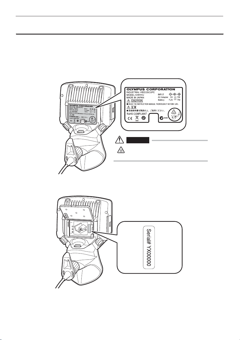
Main unit rating plate/caution plate
The safety ratings, cautions, and serial number are on stickers on the battery cover and in the
battery compartment.
If labels are missing or if their contents are illegible, contact Olympus.
Rating and caution plate
CAUTION
• Note that the tip surface of the optical adapter
is hot.
Serial number
7
Page 12
1 Unpacking
1.1 Unpacking the instrument
When unpacking the instrument, check to make sure that all of the items listed below are included.
Should anything be missing or damaged, contact your original vendor or Olympus.
Name Count
IPLEX UltraLite (main unit)
SD card 1
AC adapter 1
AC power cord 3
3P-2P adapter (For Japan only) 1
USB cable 1
Optical adapter case 1
Strap 1
Lens cleaning kit (cotton swab, brush) 1
Tip cap (4-mm type or 6-mm type) 1
Insertion tube fastening belt 1
Instructions (this document) 1
Return Request Card (For Japan only) 1
Warranty Registration Card (For Japan only) 1
Carrying case (compact zipper case) 1
*
1
* Refer to the label with packing instructions on the inside of the top lid of the carrying case for
instructions on how to pack the instrument in the carrying case.
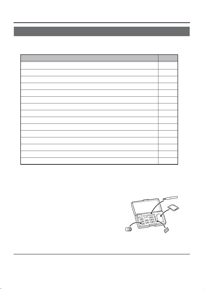
Optical adapter case
The following items are stowed in the optical adapter
case.
• Optical adapter
• O-ring
• SD card
• Lens cleaning kit brush
Stow these items in the optical adapter case for storage
when they are not in use.
The figure to the right shows the locations where each
item should be stowed.
Optical adapter
Brush
SD card
O-ring
About options
Refer to "System chart" (P. 44) for information on options.
8
Page 13
2 Nomenclature
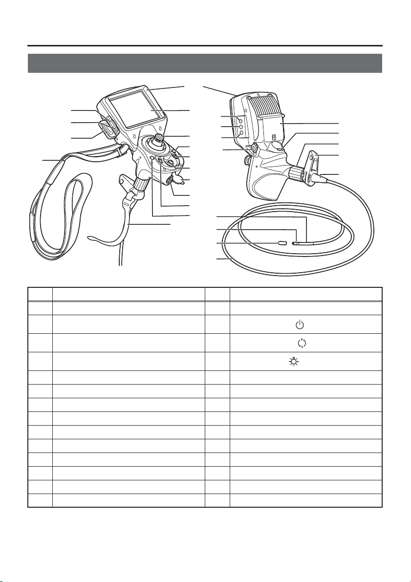
2.1 Main unit/insertion tube nomenclature
1
2
3
4
5
No. Name No. Name
1 Main unit 15 LCD monitor
2 SD card slot 16
3 USB connector 17
4 SD card cover 18
5 Strap 19 Strap holder
6 Insertion tube fastening belt 20 Angulation section
7 VIEW button* 21 Distal end
8 BRT lever 22 Tip cap
9 AC adapter connector 23 Insertion tube
10 AC adapter connector cap 24 Bend stopper
11 ENT/MENU joystick* 25 Insertion tube holder
12 ZOOM lever* 26 Angulation lock ring
13 LIVE button 27 FRZ/REC button*
14 Joystick 28 Battery cover
15
16
17
14
18
13
19
12
11
10
9
8
20
7
6
21
22
23
POWER button ( )
ROTATE button ( )
LIGHT button ( )
28
27
26
25
24
* The functions of these buttons may be different when they are long-pressed. In this manual, the term
"short-press" is used to indicate pressing a button for a short duration, while "long-press" means
holding down a button for at least one second.
9
Page 14
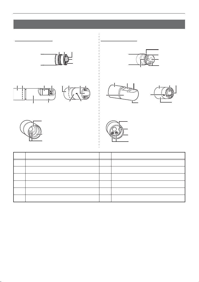
2.2 Distal end/optical adapter nomenclature
z
z
z
z
4-mm type 6-mm type
2 Nomenclature
zzDistal end
Optical adapter
778 85 59 9
11
Optical adapter internal view
No. Name No. Name
1 Optical adapter positioning cut surface 7 Nut
2 First screw thread 8 O-ring
3 Second screw thread 9 Illumination
4 Connecting screw thread 10 Index
5 Objective lens 11 Product abbreviation*
6 Electrode 12 Positioning pin
* For information about the product abbreviation, see the optical adapter instruction manual.
10
12
4
6
11
123
5
6
10
zzDistal end
Optical adapter
7
11
Optical adapter internal view
4
559
10
10
12
3
2
6
8
1
5
6
7
9
11
10
Page 15
2 Nomenclature
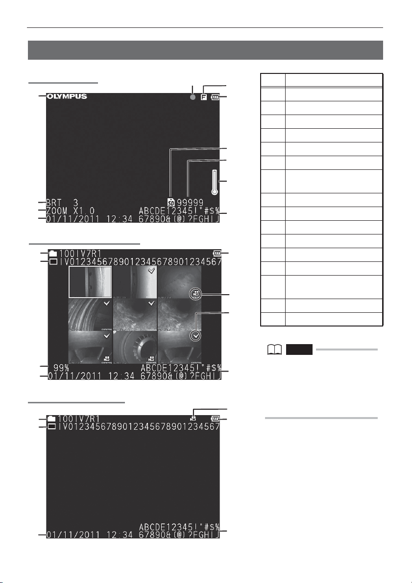
2.3 LCD monitor nomenclature
Live screen
1
2
3
4
Thumbnail screen
12
13
14
4
Retrieve screen
12
13
11
15
10
9
8
7
6
5
9
15
16
5
9
No. Name
1 Logo
2 Brightness level
3 Zoom level
4 Date/Time
5 Title
6 Temperature indicator
Number of images that
7
can be recorded
8 SD card icon
9 Battery indicator
10 Freeze indicator
11 Movie recording indicator
12 Folder name
13 File name
Remaining media
14
capacity
15 Movie image indicator
16 Mark
NOTE
• The displayed title is the title that
was entered on the Live screen the
last time the system was used.
• Should you notice any dirt, stains,
or other abnormalities on the LCD
monitor, see "6 Storage and
maintenance" (P. 33).
11
4
5
Page 16

3 Pre-observation/pre-operation
z
preparation and inspection
Be sure to finish the preparation and inspection work described in this chapter before using the
instrument. At the first sign of any abnormality, immediately stop using the instrument and perform
the required actions as described in "7 Troubleshooting" (P. 36).
Inspections are not only required before use, but should be conducted periodically.
CAUTION
• Make sure the instrument is turned off before performing pre-observation and pre-operation preparation
and inspection.
3.1 Pre-observation preparation
Remove the instrument from its carrying case.
1
Preparing the power supply.
2
When using the battery (See P.12)
When using the AC adapter (See P.13)
Preparing the power supply
Using the battery
Use your finger to pull the battery cover lock and open the cover.
Noting the orientation of the battery, insert it terminals first into the compartment and then press
down until you hear it click into place. After the battery is firmly in place, close the battery cover.
Removing the battery
Insert the tip of your finger into the depression on the right side of
the battery and lift it up while pushing on the left side with your
finger to remove it.
12
Page 17

3 Pre-observation/pre-operation preparation and inspection
Using the AC adapter
AC inlet
After connecting the provided AC power cord to the AC inlet of the AC adapter, plug the plug end
of the AC power cord securely into a 3P power outlet.
CAUTION
• Always grasp the plug when unplugging it from the electric outlet. Pulling the cord creates the risk of wire
breakage and other malfunction.
3.2 Pre-operation preparation
Turn on power. (See P.14)
1
Check the remaining battery level. (See P.14)
2
Select the display language (initial settings). (See P.28)
3
Configure date and time settings (initial settings). (See P.28)
4
Attach the optical adapter. (See P.14)
5
Check the illumination of the distal end. (See P.15)
6
Adjust white balance. (See P.27)
7
Check the angulation operation of the insertion tube. (See P.15)
8
Install the tripod adapter (when using a tripod). (See P.16)
9
Secure the insertion tube to move the instrument to another location. (See
10
P.16)
13
Conduct a pre-operation inspection. (See P.17)
11
Page 18

3 Pre-observation/pre-operation preparation and inspection
Turning on power
Hold down the POWER button ( ) for at least 3 seconds to turn on power.
Display screen and menu operations become enabled about 3 seconds after the POWER button
( ) is pressed.
Turning off power
Hold down the POWER button ( ) for at least two seconds.
Checking the remaining battery level
When operating the instrument under battery power, an indicator in the upper right corner of the
screen shows remaining battery power. The table below shows general guidelines for remaining
battery power.
Indicator Battery condition
Battery power is sufficient (100% to 60%).
Battery power is low (60% to 10%).
*1
Battery power is almost depleted (10% to 5%).
*1
*1 Do not perform any image recording or deletion operation while this indicator is displayed. If power runs
out during these operations data could be corrupted.
Battery power is close to being depleted. Charge the battery or
replace it with a charged battery (5% to 0%).
Attaching the optical adapter
1 Positioning the optical adapter with the
distal end so they are directly opposite
each other, carefully insert the optical
adapter into the distal end.
Example: For the 6-mm type
Positioning pin
Connecting screw thread
2 Turn the optical adapter nut clockwise until
the first screw thread passes over the
connecting screw thread.
3 Once past the first screw thread, turn the
optical adapter clockwise while pushing
gently until it fits into the positioning cut
surface on the distal end and can be turned no
further.
14
Page 19

3 Pre-observation/pre-operation preparation and inspection
4 Turn the nut of the optical adapter clockwise
until the second screw thread is screwed onto
the connecting screw thread. Tighten the nut
until it stops.
Removing the optical adapter
To remove the optical adapter, repeat the above attachment steps in reverse order.
Optical adapter attachment and detachment messages
Attachment or detachment of the optical adapter is automatically detected and indicated by a
message.
• Attachment
OPTICAL ADAPTER IS ATTACHED.
• Detachment
OPTICAL ADAPTER HAS BEEN DETACHED.
Also, if the screw of the nut of the optical adapter is loose, a detached message is displayed.
Checking the illumination of the distal end
CAUTION
• The Illumination emitted from the distal end can heat nearby objects and cause them to ignite. Always turn
the LIGHT button ( ) OFF when the instrument is not in use.
• If the illumination light does not light when you push the LIGHT button ( ), the optical adapter may not be
attached correctly. There is a risk that the optical adapter may fall off, refer to "Attaching the optical
adapter" (P. 14) to attach it correctly.
Attaching the optical adapter to the distal end automatically turns on illumination.
Checking the angulation operation of the insertion tube
Extend the insertion tube straight out and operate the joystick to
check for smooth angulation section operation.
Angulation movement matches the angle and direction of
joystick movement.
15
Page 20

3 Pre-observation/pre-operation preparation and inspection
Attaching the tripod adapter
Attach the tripod adapter to the instrument to use a tripod to
do observations.
Perform the following steps to install the tripod adapter.
1 Check the orientation of the tripod adapter (as
shown in the illustration on the right).
2 Screw the screw on the tripod adapter into the
screw hole on the strap holder to attach it.
3 Screw the screw into the tripod hole on the
tripod adapter to attach it.
Securing the insertion tube to move the instrument to another
location
The insertion tube can be coiled with the insertion tube fastening belt when moving the instrument
to another observation location.
After coiling the insertion tube, wrap it with the insertion tube fastening belt near the insert tube
bend stopper.
Transport the instrument by holding the main unit or by hanging it from the strap.
Tripod
hole
Holding the main unit
Stow the instrument in its carrying case when moving or transporting it over long distances.
CAUTION
• Never dangle the instrument from the insertion tube to moving it.
• After stowing the instrument in its carrying case for transport, check to make sure that the carrying case
cover is closed.
Hanging from the strap
16
Page 21

3 Pre-observation/pre-operation preparation and inspection
3.3 Pre-operation/post-operation inspections
CAUTION
• The distal end may become hot due to illumination or internal heating by electrical parts, etc. Before
attaching or detaching the optical adapter, turn the LIGHT button ( ) off and wait until the distal end is
cooled down. Especially after use in high-temperature environments, touching the distal end immediately
after turning off light creates the risk of burn injury.
• When inspecting the insertion tube, be sure to hold it at a point behind the angulation section. Otherwise,
the angulation section may be damaged.
• Also be sure to check the inspection items after using the instrument.
Inspection
location
Overall Any dirt, sand, or other foreign matter on the insertion
tube, battery cover, SD card cover?
Any cracks, scratches, or other defects to the insertion
tube, battery cover, or SD card cover?
Any irregularities such as damage to or deformation of the
exterior material, buttons, joysticks, or levers?
Insertion tube,
angulation
section, distal
end
O-ring Is the O-ring missing, broken, etc.?
Any looseness in materials other than the angulation
section?
Any dirt or water droplets on the objective lens or
electrodes of the distal end?
Continued use in this condition creates the risk of
damage to the optical adapter and/or distal end.
Any build up of dirt on the optical adapter positioning
surface or threads of the distal end?
Any distal end deformation or looseness, or unusual
connecting screw wear?
Never use the instrument while there is any looseness
on the distal end. Doing so creates the risk of loose
parts falling into the inspection object.
An O-ring that is misaligned or broken can allow water
or other liquid to get into the joint between the distal end
and optical adapter, creating the risk of malfunction and
damage. In some cases, the illumination does not light.
Item If abnormality is
discovered
See "6 Storage
and
maintenance"
(P. 33).
Replacement
required.
Contact
Olympus.
See "6 Storage
and
maintenance"
(P. 33).
17
Page 22

3 Pre-observation/pre-operation preparation and inspection
Inspection
location
Optical
adapter
LCD monitor Any surface cracks or other abnormalities?
Any dirt or water on the inner or outer of the objective lens
surfaces or the inner electrodes?
Using the optical adapter inner surface electrodes while
dirt or water is present can damage the optical adapter
or the distal end.
Failure to clean electrodes properly can result in
illumination failure.
Make sure there are no deformities or foreign objects in
the threads of the screws of the optical adapter.
Note that insufficient cleaning can result in a loss of
water tightness between the optical adapter and the
distal end.
Any looseness in optical adapter components?
Never use the optical adapter if any components are
loose. Otherwise, a loose part might fall into the
inspection object.
Item If abnormality is
NOTE
The LCD monitor is manufactured based on precision
technologies. The LCD monitor may contain pixels that do
not light (visible as black dots) or light permanently (visible
as bright dots). This does not indicate a defect or
malfunction of the product.
Any fingerprints on the screen or other soiling? See "6 Storage
discovered
See "6 Storage
and
maintenance"
(P. 33)
Replacement
required.
Contact
Olympus.
and
maintenance"
(P. 33).
18
Page 23

4 Basic operation
4.1 Viewing an observation object
WARNING
• The distal end will be hot immediately after use in a high-temperature environment. Do not touch it directly.
Doing so creates the risk of burn injury.
1 Turn on optical adapter illumination.
2 While watching the display screen, insert the insertion tube into the
observation object.
Insert carefully while checking the insertion direction.
3 Use the joystick to perform angulation operations and observe the applicable
locations on the display.
Be careful not to apply excessive pushing force, twisting or tension to the insertion tube.
4 Lock the angulation section angle and direction (angulation lock) and perform
observation.
When the angulation section is at the desired angle and direction, rotate the angulation lock
ring to align the "L" and "-" marks. Fine adjustment of the angulation angle can be performed
while angulation is locked.
5 While watching the display screen, carefully withdraw the insertion tube.
If angulation is locked, first rotate the angulation lock ring to align the "F" and "-" marks to
unlock it before removing the insertion tube.
CAUTION
• Should any of the following messages appear during observation, immediately stop observation, carefully
withdraw the insertion tube, and perform the required actions as instructed in "Error messages" (P. 36).
- OVER CURRENT (ADAPTER). PLEASE TURN OFF THE POWER AND CLEAN THE ELECTRODE.
- HIGH TEMPERATURE (DISTAL END). PLEASE IMMEDIATELY PULL OUT THE INSERTION TUBE.
• Should you sense any abnormality, do not try to force the operation and carefully withdraw the insertion
tube. Note the following precautions when withdrawing the insertion tube.
- Do not try to withdraw from the observation object while angulation is locked or while the angulation
section is bent.
- If the insertion tube becomes caught on something during withdrawal, rotate the control unit gently while
continuing the withdrawal.
• A yellow temperature indicator will appear on the display if the ambient operating temperature of the distal
end reaches approximately 80°C. Note that this indicates that the upper limit of the ambient operating
temperature is being approached.
• The battery indicator flashes yellow if the battery overheats. Note that this indicates that the upper limit of
the operating temperature is being approached.
NOTE
• Increasing the insertion tube looping amount (bending amount) decreases the maximum angulation angle
limit of the angulation section. Keep the insertion tube as straight as possible to get the best operations
from the instrument.
• Angulation tends to be difficult to achieve under low temperatures.
• The LCD monitor may not display data normally when the instrument is used in an environment where
temperatures are below 0°C. Use a heater to warm the area before operation. The amount of screen noise
may increase under high ambient temperatures.
19
Page 24

4 Basic operation
z
4.2 Adjusting the image display
Still image display (Freeze)
1 While a live image is displayed, short-press the [FRZ/REC] button.
This will freeze the observation screen image and display the freeze indicator ( ) in the
upper right corner of the LCD monitor. Do not insert or withdraw the insertion tube while an
image is frozen.
2 The display image can be unfrozen by a short-press of the [FRZ/REC] button
or the [LIVE] button.
NOTE
• Freezing an image that contains high-speed action may result in a blurred image.
Enlarging an image (Zoom)
The display image can be zoomed for an enlarged view of the observation object.
Each upward press of the [ZOOM] lever enlarges the image five times.
To zoom back to the original image size, press the [ZOOM] lever downwards.
During a zoom operation, [ZOOM] will appear on the screen along with a value indicating the zoom
level (for about three seconds).
NOTE
• Images are zoomed using “digital zoom“. As a result, the image may become slightly coarse at higher
zoom factors.
Adjusting image brightness
Automatic brightness adjustment with the [BRT] lever
The [BRT] lever can be used to adjust brightness by changing the overall brightness of a live
image during observation.
While a live image is displayed, press the [BRT] lever upwards to increase overall image
brightness, or downwards to decrease it.
Performing a brightness adjustment operation will cause a value indicating the current brightness
level to appear on the screen for about three seconds.
Displaying a high-sensitivity image (monochrome boost)
The live image becomes monochrome (monochrome boost) during high-sensitivity image display.
This function is effective to provide a higher level of brightness than normal when viewing a very
dark subject, etc.
While a live image is displayed, you can switch to high-sensitivity image display by pressing the
[BRT] lever upwards until [BRT] (brightness level) reaches its maximum setting (Level 10). Note
that the image noise may increase under certain observation conditions.
20
Page 25

4 Basic operation
4.3 Recording images
Still images and movie images can be recorded during observation. Data can be stored on the
provided SD card.
Use either the provided SD card or a recommended Class 6 or higher SDHC card for storage. Use
of SDXC cards is not supported.
Loading an SD card
Format the SD card for recording images on the instrument before using it. For details about
formatting, refer to "SD card formatting (initialization)" (P. 28).
The following table shows the size of a single image and the approximate numbers of images that
can be recorded on an SD card.
Recording format Approximate single image size Approximate image capacity (1 GB)
Still images 300 KB 3,400 images
Movies (per sec.) 500 KB 30 minutes
Image recording settings must be configured using menu operations. See "5.1 Performing menu
operations" (P. 26) and "5.2 Using the live screen/freeze screen" (P. 27).
Loading an SD card
Use your finger to pull the SD card cover lock and open the cover.
Noting the orientation of the SD card, insert it into the slot until you hear it click into place. Next,
close the SD card cover.
CAUTION
• If the SD card does not slide smoothly into the slot, it could mean that it is not aligned correctly. Do not try
to force the card into the slot. Check its orientation.
Specifying the image recording format
To record the date, time, title, logo, and other on-screen information onto the image being
recorded, press the [ENT/MENU] joystick while a live screen is displayed. On the menu that
appears, select "SETUP" and then "PRINT SCREEN ON/OFF". Next, change the "PRINT
SCREEN ON/OFF" setting to "ON". (See P.27.)
NOTE
• Replaying a still image that has the date, title, and other information recorded on it may result in
overlapping of date, time, title, logo, and other text. This is not a malfunction.
21
Page 26

4 Basic operation
File names
File names are generated and assigned automatically as images are stored on an SD card. You
can change a file if you want (up to 30 alphanumeric characters and symbols).
IV0?????.***
5-digit file name serial number
The file number is assigned sequentially from 00001 to 99999.
NOTE
• You can use the FILE NAME MARK menu to specify addition of the letter ”_A”, ”_B”, or ”_C” at the end of
image file names. Use this function to categorize image files.
File name extension
".JPG" for still image files, ".AVI" for movie files.
Recording a still image
1 While a live image is displayed, short-press the [FRZ/REC] button.
This freezes the image.
2 While the freeze screen is displayed, long-press the [FRZ/REC] button again.
This records the still image.
At this time the screen will momentarily go black, and then the freeze screen will reappear.
Recording a movie image
1 While a live image is displayed, press the [FRZ/REC] button.
After a still image is recorded, the movie image recording confirmation window will appear.
2 Select "YES" and then short-press the [ENT/MENU] joystick.
This starts movie image recording. A movie recording indicator flashes on the LCD monitor
while movie recording is in progress. If you select [NO] in the moving image confirmation
window, only the still image is recorded but the moving image is not recorded.
3 To stop movie recording short-press the [FRZ/REC] button.
The flashing movie recording indicator disappears from the screen when movie recording is
complete.
NOTE
• Never attempt to insert or remove an SD card while movie recording is in progress. Doing so will cause
movie recording to stop and an error message to appear on the display.
• Recording stops automatically whenever the SD card becomes full or when the file size reaches 2 GB. An
empty 1 GB SD card has enough capacity to record approximately 30 minutes.
• Short-pressing the [VIEW] button stops movie recording and displays the retrieve screen, long-pressing
the [VIEW] button stops movie recording and displays the thumbnail screen.
22
Page 27

4 Basic operation
4.4 Replaying an image
Recorded images can be displayed using either of two screen views: a full-screen view of a single
image (retrieve screen) or a multi-image view of thumbnail images (thumbnail screen).
The thumbnail screen shows multiple images at a single glance, which makes it useful when
finding a particular image among a large group of images.
Check to make sure an SD card is loaded before starting playback.
Live screen or
freeze screen
Long-press the
[VIEW] button.
Thumbnail screen
Long-press the [VIEW]
button or short-press
the [LIVE] button.
Long-press the [VIEW] button.
Short-press the [VIEW] button or
use the [ENT/MENU] joystick.
Short-press the [VIEW]
button or [LIVE] button.
Short-press the
[VIEW] button.
Retrieve screen
Playing back on a full-screen view (retrieve screen)
1 While the live screen, freeze screen, or thumbnail screen is displayed, short-
press the [VIEW] button.
This will display a full-screen view of the newest recorded image.
2 Switch the image you want to play back.
Use the [ENT/MENU] joystick to switch the image you want to play back.
[ENT/MENU] joystick left operation
Scrolls from the currently displayed image to the image chronologically before it.
When images are sorted in descending order, performing this operation when at the last image
will return to the first image.
[ENT/MENU] joystick right operation
Scrolls from the currently displayed image to the image chronologically after it.
When images are sorted in ascending order, performing this operation when at the last image
will return to the first image.
3 Rotate the image 180° and play it back. (Rotate)
Press the [ROTATE] button to rotate the image 180°. This feature comes in handy when the
instrument is on a desk or table in an upside down position.
4 Short-press the [LIVE] button or [VIEW] button to return to the live screen.
23
Page 28

4 Basic operation
z
z
Multi-image view (thumbnail screen)
The thumbnail screen shows multiple recorded movie and still images on a single screen (nine
images per screen).
You can use the thumbnail screen to search for a desired image, or to select multiple images to
move them or delete them.
1 While the live screen, freeze screen, or retrieve screen is displayed, long-press
the [VIEW] button.
This will display a multi-image view of recorded images (up to nine images per screen).
A movie image is indicated by the movie image indicator ( ).
To select a thumbnail
Move the [ENT/MENU] joystick up, down, left or right to move the selection boundary around
the screen.
The thumbnail where the selection boundary is located is the currently selected image.
To play back an image
Select the image you want to play back and then short-press the [ENT/MENU] joystick.
This starts full-screen view playback of the selected image.
To select multiple images to move or delete them
Selecting an image and then pressing the [BRT] lever upwards will put a check mark (9) in its
upper right corner to indicate that it is selected. After selecting all of the images you want this
way, you can then perform the required menu operations to move or delete them.
To select all thumbnails
Pressing the [BRT] lever downward will put a check mark (9) in its upper right corner of all of
the thumbnails.
To remove a check mark
From a specific image only
Select the image whose check mark you want to remove, and then press the [BRT] lever
upwards.
From all thumbnails that have check marks (9)
Press the [BRT] lever downwards.
2 Rotate the image 180° and play it back. (Rotate)
Press the [ROTATE] button to rotate the image 180°. This feature comes in handy when the
instrument is on a desk or table in an upside down position.
3 Short-press the [LIVE] button or long-press the [VIEW] button to return to the
live screen.
24
Page 29

4 Basic operation
4.5 Using images on a PC
Use the provided USB cable to import recorded images directly from the instrument to your
computer.
1 On the live screen, use the SETUP menu to select [PC] to configure the
instrument's PC settings.
2 Use the USB cable to connect the instrument to a PC that is running.
On the PC, click the files you want to play.
3 Shutdown operation of the computer.
Safely remove hardware from the PC and then turn the instrument off.
CAUTION
• Connect only the provided USB cable to the USB connector for connection of a PC only. Otherwise,
malfunction might occur.
• The instrument will not display the live screen while recorded images are being displayed on a PC screen.
25
Page 30

5 Menu operations and functions
5.1 Performing menu operations
1 Long-press the [ENT/
MENU] joystick.
This displays the main
menu.
2 Tilt the [ENT/MENU]
joystick up, down, left
or right to select the
menu item you want to
execute.
3 Short-press the [ENT/
MENU] joystick to apply
the setting and return
to the screen in which
the main menu was
displayed.
NOTE
• Long-pressing the [ENT/MENU] joystick while doing menu operations, returns to the screen in which the
main menu was displayed.
26
Page 31

5 Menu operations and functions
5.2 Using the live screen/freeze screen
Menu display and functions
The settings described in the table below can be configured using the live screen/freeze screen
menu.
Available settings Menu
*: Initial default
Title input
A title can be displayed in the live screen and in registered images. Input
can be up to 30 characters.
See "Inputting a title" (P. 29).
White balance adjustment (Live screen only)
Specifies whether to perform white balance.
• CANCEL : Do not adjust.
• EXECUTE : Adjust.
After changing the optical adapter, capture an image of a white object, such
as a piece of paper, from a distance of 50 to 60 mm.
The following menu is in the "SETUP" menu.
PC USB connection
Specifies whether to establish a USB connection with a PC.
Specifying USB connection enables import of instrument images to a PC.
• CANCEL : Do not configure PC connection settings.
• EXECUTE : Configure PC connection settings.
[FRZ/REC] button image type setting
Specifies the type of image that is recorded when a record operation is
performed with the [FRZ/REC] button. Long-pressing the [FRZ/REC] button
performs one of the following operations.
• STILL+MOVIE*:
Live screen :Records still image and movie.
Freeze screen :Records still image only.
• STILL ONLY:
Live screen :Records still image only.
Freeze screen :Records still image only.
TITLE INPUT
WHITE BALANCE
PC
REC FUNCTION
Date, title, and other information recording
Specifies date, time, title and logo and other information included on the
display should be recorded in images.
• ON : Record information.
• OFF* : Do no record information.
27
PRINT SCREEN
ON/OFF
Page 32

5 Menu operations and functions
Available settings Menu
Display information setting
Specifies whether display information (date and time, title, etc.) should be
shown on the LCD monitor.
This setting can also be used to specify the type of information to be
displayed.
• ALL : Show the date, time, title, "OLYMPUS" logo,
zoom level, and brightness level.
• DATE/TIME/LOGO: Show the date, time, title, and "OLYMPUS" logo.
• DATE/TIME : Show the date, time, and title.
• OFF : Hide information.
Letter appending to the end of image file names
Specifies whether a letter should be added to names assigned to recorded
image files. This feature helps to categorize image files.
• ON : Append letter.
You can select from among "_A", "_B", and "_C".
Selecting "ON" displays a dialog box for selecting the
letter to be appended to each image file name.
• OFF* : Do not append letter.
Specifies a folder for image recording and playback
Specifies a folder for image recording and playback.
The data of images that are recorded is saved in the specified folder.
During playback, the recorded data in the specified folder is displayed.
SD card formatting (initialization)
• CANCEL : Do not format the card.
• EXECUTE : Format the card.
DATE/TIME/
LOGO
FILE NAME MARK
CHANGE
FOLDER
MEDIA FORMAT
CAUTION
• Never remove the SD card while formatting is in progress.
• Formatting an SD card deletes all of its data.
Date and time settings
Configures date and time settings.
See "Setting the date and time" (P. 31).
Display language selection
Specifies the language used for menus and messages.
English and other languages are supported.
See "Changing the display language" (P. 31).
DATE TIME
LANGUAGE
28
Page 33

5 Menu operations and functions
z
z
123
32
Inputting a title
The following are the two methods that can be used to input a title.
• Input text from the on-screen keyboard
• Select a preset title
Input text from the on-screen keyboard
1 Select the input mode and then press the [ENT/MENU] joystick.
2 Select the buttons of the characters you want and then press the [ENT/MENU]
joystick.
The characters you input appear in the title input box. Edit the text as required.
To delete characters
• To delete a single character, move the cursor to it, select [DELETE], and then press the [ENT/
MENU] joystick.
• To delete all input characters, select [CLEAR] and then press the [ENT/MENU] joystick.
To input a space
Move the cursor to the location where you want to input the space, select [SPACE], and then
press the [ENT/MENU] joystick.
3 Select [EXECUTE] and then press the [ENT/MENU] joystick.
This displays the title you input on the LCD monitor.
Selecting a preset title for input
With this procedure, you select a preset character string and use it to input a title.
For information about how to register frequently used text strings, see "Registering a character
string as a preset title" (P. 30).
1
1 Select [PRESET] and then press the [ENT/MENU] joystick.
This displays a list of preset titles. To cancel preset title selection, press the [ENT/MENU]
joystick left or right to close the list screen.
29
Page 34

5 Menu operations and functions
2 Select the preset title you want from the list and then press the [ENT/MENU]
joystick.
The text string you select appears in the title input box.
Repeat steps 1 and 2 to complete input of the title.
NOTE
• The preset title list has two pages. To change pages, select the text string in line 1 or line 7 of the currently
displayed page and then tilt the [ENT/MENU] joystick upwards or downwards.
3 Select [EXECUTE] and then press the [ENT/MENU] joystick.
This displays the title you selected on the LCD monitor.
Registering a character string as a preset title
After you register commonly used character strings to favorites, you can recall them when you are
inputting titles. You can register a maximum of 14 character strings to preset titles.
1
32
1 Input the character string you want to register into the title input box.
For details about inputting, see "Inputting a title" (P. 29).
2 Select [ENTRY] and then press the [ENT/MENU] joystick.
A list of preset titles is displayed.
To cancel preset title registration, press the [ENT/MENU] joystick left or right to close the list
screen.
NOTE
• The preset title list has two pages. To change pages, select the text string in line 1 or line 7 of the currently
displayed page and then tilt the [ENT/MENU] joystick upwards or downwards.
3 Select the line where you want to store the string and then press the [ENT/
MENU] joystick.
The text string you input in the title input box is registered to preset titles.
Registering a preset title overwrites anything currently in the line you specify in the list. This
means you can delete a preset title by performing the registration operation while the title input
box is blank.
4 Press [ENT/MENU] joystick towards the left.
This closes the preset title list screen.
30
Page 35

5 Menu operations and functions
Changing the display language
Use the procedure below to select the language for menus and error messages that appear on the
display.
SETUP > LANGUAGE > Select a language.
Selecting a language displays the message to let you know that the process is being performed.
After the message disappears, LCD monitor contents will be in the language you selected.
NOTE
• After the language setting is changed, it may take longer than normal for screen display functions to be
performed. This does not indicate malfunction.
Setting the date and time
Use the procedure below to configure date and time settings.
SETUP > DATE TIME > Set DMY, H:M.
Be sure to set the correct date and time before using the instrument for the first time.
Date and time information is shown on the display and is also recorded on the print screen. Data
recording is also performed in accordance with date and time information.
31
Page 36

5 Menu operations and functions
5.3 Using the thumbnail/retrieve screens
Menu display and functions
The menu displayed on the thumbnail/retrieve screen can be used for the following settings.
Available settings Button
Image delete
• CANCEL : Do not delete image.
• EXECUTE : Delete image.
On the retrieve screen, the currently displayed image is deleted.
On the thumbnail screen, the currently selected image or all images that are
check marked (9) are deleted.
Move image files to folder (Thumbnail screen only)
Moves recorded images to a different folder.
The currently selected image or all images that are check marked (9) on the
thumbnail screen are deleted.
Rename file (Thumbnail screen only)
Changes the name of a recorded image file (within 30 letters).
Specifies a folder for image recording and playback (Thumbnail screen
only)
Specifies a folder for image recording and playback.
The data of images that are recorded is saved in the specified folder.
During playback, the recorded data in the specified folder is displayed.
Create folder (Thumbnail screen only)
Creates a new folder.
The initial default is "100IPLEX".
Rename folder (Thumbnail screen only)
Changes the name of a folder. (Name may be up to 30 characters, but only 8
characters appear on screen.)
DELETE
MOVE FILE
RENAME FILE
CHANGE FOLDER
MAKE FOLDER
RENAME FOLDER
NOTE
• You can use only alphanumeric characters and symbols for folder and file names. Some symbols are
unavailable for folder and file names also.
• To cancel a file move or rename folder operation, press the [ENT/MENU] joystick to the left.
32
Page 37

6 Storage and maintenance
6.1 Replacing the battery
Though the battery life depends on the operating environment and frequency of use, replacement
of the battery is recommended whenever the battery operation time becomes very short.
Contact Olympus about changing the battery.
For details about how to load and remove the battery, see "Using the battery" (P. 12).
CAUTION
• Never use a battery other than the one specified by Olympus. Otherwise, failure of the instrument may not
only lead to a malfunction but also a fire.
• Be careful not to leave any foreign objects in the battery compartment when replacing the battery.
Otherwise, a fire or malfunction may result.
6.2 Replacing the O-ring
6-mm type
Apply silicon grease to the spare O-ring that comes with the optical adapter and replace it.
4-mm type
Contact Olympus.
6.3 Cleaning components
Cleaning the insertion tube
Dirt or other foreign matter on the insertion tube
Wipe with a clean soft cloth.
Dirty water, machine oil, or other liquid on the insertion tube
Wipe with a soft cloth or cotton swab, and then wash thoroughly with a piece of gauze or other
material moistened with a neutral detergent. Next, use a clean, soft piece of soft gauze moistened
with clean water, and then wipe the insertion tube dry of all moisture.
CAUTION
• Clean the insertion tube immediately after withdrawing the insertion tube. Leaving the insertion tube very
dirty for long periods can cause it to become corroded.
• Do not use a hard cloth or hard brush for cleaning the insertion tube. Otherwise, the equipment may be
damaged.
• Do not clean the optical adapter under running water. Otherwise, the equipment may be damaged.
33
Page 38

6 Storage and maintenance
Cleaning the distal end
Dirt or water droplets on the objective lens or electrodes of the distal end
Grasping the rigid portion of the distal end, use a clean, soft piece of gauze or a cotton swab to
wipe off the dirt or water. You could also use the brush to brush away dirt and water.
Best results may be obtained using a commercially available absolute ethanol or isopropyl alcohol.
Build up of dirt on the optical adapter positioning surface or threads of the distal end
Use the brush provided with the cleaning kit to brush away built up dirt.
Note that insufficient cleaning can result in a loss of water tightness between the optical adapter
and the distal end.
Cleaning the optical adapter
Dirt or water on the inner and outer surfaces of the objective lens and the electrodes
Use a piece of clean, soft gauze or cotton swab to wipe off dirt and water. You could also use the
brush to brush away dirt and water.
Cleaning dirt from the optical adapter outer surface while attached to the distal end
Grasping the rigid portion of the distal end, wipe the optical adapter. Best results may be obtained
using a commercially available absolute ethanol or isopropyl alcohol.
CAUTION
• Using the optical adapter electrodes while dirt or water is present may cause damage to the optical
adapter or the distal end.
• Failure to clean electrodes properly can result in illumination failure.
Dirt on the inner surface of the optical adapter
Moisten a cotton swab with a commercially available absolute ethanol
or isopropyl alcohol and continue cleaning until doing so leaves no
dirt on the cotton swab. Clean in the sequence (1), (2), (3) as shown
in the nearby illustration. Spin the cotton swab while cleaning.
Also, for thorough cleaning, turn the optical adapter while doing (2)
and (3).
CAUTION
• Note that insufficient cleaning can result in a loss of water tightness between the optical adapter and the
distal end.
• Cleaning should be done periodically in order to maintain water resistance.
34
Page 39

6 Storage and maintenance
Cleaning the LCD monitor
LCD monitor viewing problems due to fingerprints and dirt
Wipe the LCD monitor with a soft cloth dampened with clean water. Next, lightly wipe it with a
clean, dry cloth.
CAUTION
• Never use a chemically treated cloth or strong detergent, such as benzine or alcohol. Doing so may
damage the surface of the LCD monitor.
• Do not use a cloth that is hard, dirty, or has foreign matter on it. Doing so may damage the surface of the
LCD monitor.
Cleaning the main unit
Dirty main unit
Wipe the main unit with a soft cloth dampened with clean water. Next, lightly wipe it with a clean,
dry cloth. Also wipe all dirt, water, and other foreign matter from the battery cover, SD card cover,
and the inside of the AC adapter connector.
CAUTION
• Do not rinse the instrument with running water. Otherwise, the equipment may be damaged.
6.4 Storage precautions
Store this product under normal room temperature and humidity.
CAUTION
• Never subject cables to severe bending, pulling, binding, twisting, or crushing forces. Do not allow a cable
to be exposed to heat, which can melt its covering. Otherwise, cable might be damaged, which can lead to
fire and electric shock.
1 Turn off power and remove the battery or unplug the AC adapter.
2 Unlock the angulation lock and straighten the angulation section, then store it
according to the label with packing instructions.
3 Store the equipment on a level surface in a clean, dry and stable place.
35
Page 40

7 Troubleshooting
WARNING
• Never use the instrument if there is any abnormality. Otherwise, the instrument may malfunction and the
user may also be injured fatally, critically or seriously.
Inspect the equipment as described in "3 Pre-observation/pre-operation preparation and
inspection" (P. 12), do not use the equipment if there are any obvious malfunctions. Contact
Olympus for repairs. Should even the slightest irregularity be suspected, do not use the instrument.
Perform the actions described in "7.1 Troubleshooting guide" (P. 36). If the problem cannot be
resolved by the described remedial action, stop using the instrument and send it to Olympus for
repair.
7.1 Troubleshooting guide
Error messages
Message Cause and recommended action
NO RECORDING MEDIA.
An SD card is not loaded.
➝Load an SD card and try again.
RECORDING MEDIA FULL.
THIS IMAGE CANNOT BE
RETRIEVED.
RECORDING MEDIA IS LOCKED.
PLEASE UNLOCK.
RECORDING MEDIA ERROR.
PLEASE FORMAT THE RECORDING
MEDIA.
IMAGER ERROR.
PLEASE TURN OFF THE POWER.
OPTICAL ADAPTER HAS BEEN
DETACHED.
OVER CURRENT (ADAPTER).
PLEASE TURN OFF THE POWER
AND CLEAN THE ELECTRODE.
The SD card is full.
➝Delete unneeded data to free up space or replace with a new SD card.
The image was not recorded with this instrument.
➝Only images recorded with this instrument can be displayed.
The SD card is locked.
➝Unlock the SD card you are using and then replace it.
The format of the SD card cannot be recognized.
➝Format the SD card on the instrument.
The self-check function activated and prompted termination of operation.
➝Stop inspection and turn the instrument off, then on again.
The optical adapter has detached.
➝Temporarily pause inspection and reattach the optical adapter.
(See "3.2 Pre-operation preparation" (P. 13).)
An abnormality was detected in the distal end electrode.
➝Immediately withdraw the insertion tube from the observation object and
turn off power. Clean the distal end and optical adapter electrode ("6.3
Cleaning components" (P. 33)) and reattach the optical adapter
("Attaching the optical adapter" (P. 14)).
36
Page 41

7 Troubleshooting
Message Cause and recommended action
HIGH TEMPERATURE (DISTAL
END).
PLEASE IMMEDIATELY PULL OUT
THE INSERTION TUBE.
This message prompts you to stop inspection because the self-check
function was triggered because the distal end was overheating.
➝Immediately withdraw the insertion tube from the observation object.
NOTE
• This message appears before the atmospheric temperature of the distal
end of the insertion tube reaches the maximum operating ambient
temperature.
LOW BATTERY.
PLEASE CONNECT TO THE AC
ADAPTER OR TURN OFF THE
POWER.
BATTERY TEMPERATURE IS HIGH.
PLEASE CONNECT TO THE AC
ADAPTER OR TURN OFF THE
POWER.
THE SPECIFIED FOLDER NAME
ALREADY EXISTS.
PLEASE CHOOSE ANOTHER NAME.
THE SPECIFIED FILE NAME
ALREADY EXISTS.
PLEASE CHOOSE ANOTHER NAME.
Common problems
Problem Cause and recommended action
The LIGHT button ( ) is not on.
➝Turn on the LIGHT button ( ).
The optical adapter is not attached properly.
Illumination does not light.
➝Attach the optical adapter properly.
Electrodes on the optical adapter or the insertion tube distal end are dirty.
➝Wipe with a clean piece of gauze or a cotton swab.
The LEDs on the distal end of the optical adapter are inoperable.
➝Replace the optical adapter with a new one.
Battery voltage is low.
➝Stop all image recording, copy, and delete operation, SD card format
operations, etc., and immediately replace the battery. Or you connect the
AC adapter.
Battery temperature up, self-check function activated.
➝Connect the AC adapter or turn off the power.
A folder with the same name as the one you are creating already exists.
➝Specify a different folder name.
A file with the same name as the one you are creating already exists.
➝Specify a different file name.
Or use a brush to remove foreign matter ("Cleaning the optical adapter" (P. 34)).
The illumination is dim.
37
The optical adapter tip is dirty.
➝Wipe with a clean piece of gauze or a cotton swab.
Extended use under high ambient temperatures causes decreased light
emissions.
➝Replace the optical adapter with a new one.
Page 42

Problem Cause and recommended action
The optical adapter cannot be
attached to the insertion tube.
7 Troubleshooting
A foreign object is stuck to the screws.
➝Wipe with a clean piece of gauze or a cotton swab.
The optical adapter in use is not a designated optical adapter for this system.
➝Use the designated optical adapter.
The installation procedure is not correct.
➝Reinstall using the correct procedure ("Attaching the optical adapter" (P. 14)).
The optical adapter cannot be
removed from the insertion
tube.
The system cannot be turned
on.
The system cannot be turned
off.
The image is not sharp.
The image brightness is not
optimum.
Color reproduction is poor.
The image is noisy.
The nut of the optical adapter is rotated in the wrong direction.
➝Reinstall using the correct procedure ("Attaching the optical adapter" (P. 14)).
The AC adapter or the battery is not connected.
➝Connect the AC adapter or the battery correctly. (See "Preparing the power
supply" (P. 12).)
The Power button is not on.
➝Turn on the main unit POWER button ( ).
A non-designated AC adapter or battery is connected.
➝Use the designated AC adapter or battery.
The main unit is damaged.
➝Remove the AC adapter or the battery from the main unit to turn off the power.
The objective lens on the distal end or the optical adapter is dirty.
➝Wipe with a clean piece of gauze or a cotton swab.
The optical adapter is attached improperly.
➝Attach the optical adapter properly.
The automatic brightness control is set erroneously.
➝Perform the [BRT] lever operation to configure the proper setting.
The objective lens on the distal end or the optical adapter is dirty, or the
illumination on the optical adapter distal end is dirty.
➝Wipe with a clean piece of gauze or a cotton swab.
Extended use under high ambient temperatures causes decreased light
emissions.
➝Replace the optical adapter with a new one.
The white balance is set improperly.
➝Re-adjust white balance.
The automatic brightness control is set erroneously.
➝Perform the [BRT] lever operation to configure the proper setting.
Angulation cannot be returned
to its original attitude.
Operation load for articulation is
getting heavier.
All the functions stopped during
motion image recording.
The angulation lock is engaged.
➝Rotate the angulation lock ring to release the angulation lock.
Angle lock is engaged
➝Rotate the angulation lock ring to release the angulation lock.
The SD card being used for image recording is not the one provided and is not
one recommended by Olympus.
➝Remove the AC adapter or the battery from the main unit to turn off the power.
➝Use an SD card recommended by Olympus.
38
Page 43

7 Troubleshooting
7.2 Requesting repair of this product
WARNING
• Olympus is not liable for any accidents or instrument damage that occurs as a result of repairs attempted
by non-Olympus personnel.
CAUTION
• Olympus will not repair an instrument contaminated by noxious substances.
Contact Olympus before requesting repair of this instrument. Include a detailed description of the
malfunction and the conditions under which it occurs when returning the instrument.
Malfunctions that occur during the warranty period are done at no charge according to the warranty
agreement. Be sure to attach the warranty agreement when returning the instrument for repairs.
Repair will be charged if the warranty agreement is not attached. The freight fees are paid by the
user even if repairs are done free of charge.
39
Page 44

8 Specifications
8.1 Operating environment
Operating temperatures
Operating atmospheric pressure
Operating environment humidity
Liquid resistance
Waterproofing
Insertion tube
Other parts than above
Insertion tube In air : Normal pressure (1,013 hPa)
Other parts than above In air : Normal pressure (1,013 hPa)
All parts 15 to 90% (relative humidity)
Insertion tube No trouble when exposed to machine oil, light oil or 5% saline solution.
Other parts than above
Insertion tube Waterproof construction. Can be used underwater with the optical adapter
Other parts than above Water resistant proof construction. Use in water is not supported. The instrument is
In air : -25 to 100°C
In water: 10 to 30
In air : -10 to 40°C (Battery-powered operation)
0 to 40
°C (AC adapter-powered operation)
In water: 1,013 to 1,368 hPa
attached.
not water-resistant if the battery cover, SD card cover, or AC adapter connector cap
is open.
°C
CAUTION
• Meeting operating environment specifications does not constitute any guarantee against damage to or
malfunction of this equipment.
• Use AC adapter and battery charger indoors (normal temperature).
8.2 Other specifications
Optical system
For optical adapter specifications, see "8.3 Optical adapter specifications" (P. 43).
Distal end
Outer diameter V84 Series: φ4.0 mm
Distal end rigid section
length
Angulation IV8420U, IV8435U, IV8620U : UP, DOWN, RIGHT and LEFT each 130° *
Flexible section
Flexibility IV84 series: Fixed hard tube from the distal end to the main unit.
Outer diameter IV84 series: φ4.0 mm
Index lines An orange line is drawn 500 mm from the distal end. White lines are drawn at every
Total length IV8420U: 2 m IV8435U: 3.5 m
V86 Series: φ6.0 mm
See the distal end rigid section length specification of the optical adapter in use.
IV8635U : UP, DOWN, RIGHT and LEFT each 120° *
*when insertion tube is straight.
IV86 series: TF tube with flexibility gradually increasing toward the distal end.
IV86 series: φ6.0 mm
1,000 mm from the distal end. The number of white lines is increased at every
1,000 mm (1 line at 1,000 mm, 2 lines at 2,000 mm).
IV8620U: 2 m IV8635U: 3.5 m
40
Page 45

8 Specifications
Main unit
Dimensions 120(W) x 190(H) x 190(D) mm (without insertion tube and cable)
Weight
(including battery)
LCD panel 3.7-inch VGA
Input/Output connector
USB connector Mini-B , USB standard
Power supply
Battery Model : IB-1
AC adapter Model : SA115B-05V
Battery charger Model : BCS-1
Power consumption MAX 7 W
Recording media SDHC card (class 6 or later)
Still image recording
Resolution H640 x V480 (Pixels)
Recording format Files are stored as compressed JPEG format (Exif 2 compliant).
Still image retrieval
Restrictions Images recorded on the instrument can be played back.
Moving image recording
Resolution H640 x V480 (Pixel)
Recording format AVI format Xvid MPEG-4 compression
Moving image playback
Restrictions Images recorded on IPLEX UltraLite (this instrument) can be played back.
Carrying case dimensions and weight
Dimensions 460 (W) x 360 (H) x 165 (D) mm
Weight Approximately 1.7 kg (IV8420U with all items stowed: 3.5 kg)
Manufacturer OLYMPUS CORPORATION TOKYO, JAPAN
IV8420U 700 g
IV8435U 760 g
IV8620U 800 g
IV8635U 900 g
The operating environment is shown below.
Windows XP (SP3 or later), Windows Vista, or Windows 7
Nominal voltage: 7.2 V
Battery powered operating time: 90 minutes (based on new battery)
For details, refer to the instruction manual of your battery.
Designated AC adapter can be connected to AC adapter connector.
Input voltage: 100 V to 240 V AC
Frequency: 50/60 Hz
Output voltage: 5 V
Input voltage: 100 V to 240 V AC
Frequency: 50/60 Hz
For details, refer to the instruction manual of battery charger.
Playback on Windows Media Player supported.
(Provided that Windows Media Player Ver.11 or later and Xvid video codec are
installed.)
NOTE
• The images recorded with the instrument can be displayed on a computer, etc., but playback on the
instrument of images recorded with an image recording device such as a digital camera or a computer is
not supported.
• Windows Media Player is either a registered trademark or trademark of Microsoft Inc. in the U.S. and/or
other countries.
41
Page 46

External application standard
8 Specifications
Low Voltage Directive and
EMC Directive
FCC Information This product conforms to the following.
WEEE Directive The following applies to the mark to the left.
RoHS Directive RoHS compliance model
Chinese RoHS Directive This mark indicates the environmental protection use period applicable to electronic
This product conforms with the following directives.
• Directive 2006/95/EC concerning electrical equipment designed for use within certain
voltage limits.
• Directive 2004/108/EC concerning electromagnetic compatibility when used in
combination with devices bearing CE marking either on the products or in its
instructions.
• This device is designed for use in industrial environments for the EMC performance.
Using it in a residential environment may affect other equipment in the environment.
• Part 15 of the FCC Rules
Operation is subject to the following two conditions: (1) this device may not cause
harmful interference, and (2) this device must accept any interference received,
including interference that may cause undesired operation.
• FCC WARNING
Changes or modifications not expressly approved by the party responsible for
compliance could void the user's authority to operate the equipment.
In accordance with European Directive 2002/96/EC on Waste Electrical and Electronic
Equipment, this symbol indicates that the product must not be disposed of as unsorted
municipal waste, but should be collected separately.
Refer to your local Olympus distributor for return and/or collection systems available in
your country
information products sold in China in accordance with the ”Management Methods for
Controlling Pollution by Electronic Information Products” of February 28, 2006 and the
”Requirements Concerning Pollution Control Markings for Electronic Information
Products.”
(Caution) During the environmental protection use period harmful substances will not be
emitted when used under proper conditions. However, it does not guarantee functional
performance of the product during the said period.
42
Page 47

8 Specifications
8.3 Optical adapter specifications
For 4-mm type insertion tube
When the optical adapter is mounted on the insertion tube.
AT120D/NF
-IV84
Product abbreviation 120DN V84 120DF V84 120SN V84 120SF V84
Character color Red Green Red Green
Optical system Field of view
Direction of view Forward Forward Side Side
Depth of field
Distal end
Outer diameter
Rigid distal end length
*1
*2
*3
120° 120° 120° 120°
4 to 190 mm 25 to ∞ mm 1 to 20 mm 6 to ∞ mm
φ4.0 mm φ4.0 mm φ4.0 mm φ4.0 mm
19.7 mm 19.6 mm 22.2 mm 22.2 mm
• *1 Indicates the range within which the image can be viewed clearly.
• *2 Can be inserted into a φ4.0 mm hole when mounted on the insertion tube.
• *3 Indicates the length of the rigid portion at the insertion tube
For 6-mm type insertion tube
When the optical adapter is mounted on the insertion tube.
AT40D
-IV86
Product abbreviation 40D V86 80DN V86 80DF V86 120DN V86
Character color Black Red Green Red
Optical system Field of view
Direction of view Forward Forward Forward Forward
Depth of field
Distal end
Optical system Field of view
Distal end
Outer diameter
Rigid distal end length
Product abbreviation 120DF V86 80S V86 120SN V86 120SF V86
Character color Green Black Red Green
Direction of view Forward Side Side Side
Depth of field
Outer diameter
Rigid distal end length
*1
*2
*3
*1
*2
*3
• *1 Indicates the range within which the image can be viewed clearly.
• *2 Can be inserted into a φ6.0 mm hole when mounted on the insertion tube.
• *3 Indicates the length of the rigid portion at the insertion tube
40° 80° 80° 120°
200 to ∞ mm 8 to ∞ mm 35 to ∞ mm 4 to 190 mm
φ6.0 mm φ6.0 mm φ6.0 mm φ6.0 mm
19.8 mm 19.8 mm 19.8 mm 19.8 mm
AT120D/FF
-IV86
120° 80° 120° 120°
25 to ∞ mm 18 to ∞ mm 1 to 25 mm 5 to ∞ mm
φ6.0 mm φ6.0 mm φ6.0 mm φ6.0 mm
19.8 mm 25.2 mm 25.2 mm 25.2 mm
AT120D/FF
-IV84
’s distal end when mounted.
AT80D/NF
-IV86
AT80S
-IV86
’s distal end when mounted.
AT120S/NF
-IV84
AT80D/FF
-IV86
AT120S/NF
-IV86
AT120S/FF
-IV84
AT120D/NF
-IV86
AT120S/FF
-IV86
43
Page 48

Appendix
System chart
Optical adapter (optional)
4-mm type
• AT120D/ NF-IV84
• AT120D/ FF-IV84
• AT120S/ NF-IV84
• AT120S/ FF-IV84
IPLEX UltraLite
main unit
4-mm type
• IV8420U
• IV8435U
6-mm type
• IV8620U
• IV8635U
Optical adapter case
6-mm type
• AT40D-IV86
• AT80D/ NF-IV86
• AT80D/ FF-IV86
• AT120D/ NF-IV86
• AT120D/ FF-IV86
• AT80S-IV86
• AT120S/ NF-IV86
• AT120S/ FF-IV86
Tip cap
Rigid sleeve (optional)
4-mm type
• MAJ-1737 (For IV84)
6-mm type
• MAJ-1253 (For IV86)
Insertion tube
Stra p
fastening belt
Tripod adapter MAJ-2017
(optional)
SD card
Lens cleaning kit
Compact
zipper case
Carrying case
Pelican case
MAJ-2019
(optional)
AC adapter
Battery IB-1
(optional)
Battery charger
BCS-1
(optional)
USB cable
Computer
(commercially available)
44
 Loading...