

Page 1

INSTRUCTIONS
INDUSTRIAL VIDEOSCOPE
IPLEX MX II series
Page 2

Page 3

Contents
Warning and Rating Plates............................................ 1
1. Rating plate A.......................................................................................... 1
2. Rating plate B.......................................................................................... 1
3. Warning plate .......................................................................................... 2
Important Information – Please Read Before Use....... 3
Intended use.............................................................................................. 3
Instruction manual.................................................................................... 3
Combined ancillary equipment................................................................ 3
Repair and modification .......................................................................... 3
Signal words.............................................................................................. 4
Dangers, warnings and cautions............................................................. 4
Handling of the battery............................................................................. 7
Product configurations of the IPLEX MX II series.................................. 9
Chapter 1 Checking the package contents ........... 10
1.1 Checking the package contents................................................ 10
IPLEX MX II series package contents....................................................... 10
Chapter 2 Instrument nomenclature and
functions ................................................. 11
2.1 System nomenclature ................................................................ 11
2.2 Main unit nomenclature and functions..................................... 13
2.3 Control unit nomenclature and functions ................................ 14
Chapter 3 Preparation and inspection
before observation................................. 16
3.1 Transportation of the case......................................................... 16
When using the handle ............................................................................. 16
Taking the instrument out of the case....................................................... 17
i
Page 4

3.2 Setting up the main unit............................................................. 19
Using the handle ....................................................................................... 21
3.3 Preparing the power supply ...................................................... 22
Supplying power from the battery ............................................................. 22
Supplying power from the AC adapter ...................................................... 24
3.4 Inspecting the insertion tube..................................................... 25
Inspecting the external appearance of the insertion tube ......................... 25
Inspecting the insertion tube distal end..................................................... 25
3.5 Inspecting the side view mirror adapter (optional)
(for IV8630M) ............................................................................... 27
Checking the side view mirror adapter and connection screws ................ 27
Attaching and detaching the side view mirror adapter .............................. 28
Inspecting the parts of the side view mirror adapter ................................. 30
3.6 Inspecting the control unit and the universal cable................ 31
3.7 Inspecting the LCD monitor....................................................... 32
Inspecting the external appearance.......................................................... 32
3.8 Mounting of the control unit on the main unit ......................... 33
3.9 Attaching and detaching the strap............................................ 36
Attaching the strap .................................................................................... 36
Removing the strap................................................................................... 39
Chapter 4 Basic operations .................................... 40
4.1 Turning on the power................................................................. 40
Turning the power on ................................................................................ 40
Checking the LCD monitor image ............................................................. 41
Indicator display ........................................................................................ 41
Display language setting ........................................................................... 41
Date and time settings .............................................................................. 42
Checking the illumination lighting.............................................................. 42
White balance adjustment......................................................................... 42
Checking the angulation functions ............................................................ 42
Checking the angulation lock .................................................................... 43
ii
Page 5

4.2 Inserting the insertion tube ....................................................... 44
Holding the control unit and insertion tube................................................ 44
Inserting the insertion tube........................................................................ 45
Angulation operation ................................................................................. 46
4.3 Withdrawing the insertion tube ................................................. 47
Releasing the angulation lock ................................................................... 47
Withdrawing the insertion tube.................................................................. 47
4.4 Adjusting the image ................................................................... 48
Still image (freeze) .................................................................................... 48
Zoom......................................................................................................... 48
Adjusting the brightness............................................................................ 49
Monochrome boost ................................................................................... 49
4.5 Recording the image .................................................................. 50
Image recording preparation..................................................................... 50
Recording a still image.............................................................................. 52
4.6 Replaying the image................................................................... 53
Quick replay of most recent image............................................................ 53
Slide retrieval ............................................................................................ 53
4.7 Displaying a live image on an external monitor ...................... 54
Chapter 5 Menu operations and functions............ 55
5.1 Operating menu .......................................................................... 55
Menu operations ....................................................................................... 55
Example of operations .............................................................................. 55
5.2 Using the live screen/frozen screen ......................................... 57
Live screen/frozen screen menu display and functions ............................ 57
Inputting the title........................................................................................ 58
Setting the date and time .......................................................................... 60
Language selection ................................................................................... 62
5.3 Using the retrieve screen........................................................... 63
Retrieve screen menu display and functions ............................................ 63
Delete image............................................................................................. 63
iii
Page 6

Chapter 6 Operations on a computer..................... 65
6.1 Using recorded images on a computer .................................... 65
Reading images with a computer.............................................................. 65
Chapter 7 Storage and maintenance...................... 66
7.1 Remaining battery power........................................................... 66
7.2 Replacing the battery ................................................................. 67
Replacing the battery ................................................................................ 67
7.3 Cleaning....................................................................................... 69
Cleaning the insertion tube ....................................................................... 69
Cleaning the LCD monitor......................................................................... 69
Cleaning the main unit and control unit ..................................................... 70
7.4 Repacking the case .................................................................... 71
Locking the case ....................................................................................... 73
7.5 Storage precautions................................................................... 74
Chapter 8 Troubleshooting..................................... 75
8.1 Troubleshooting guide............................................................... 76
Error messages......................................................................................... 76
General troubles during operation............................................................. 78
8.2 Returning the instrument for repair .......................................... 80
Chapter 9 Specifications......................................... 81
9.1 Operating environment .............................................................. 81
9.2 Other specifications ................................................................... 82
Carrying case specifications ..................................................................... 86
Side view mirror adapter specifications..................................................... 87
External application standard.................................................................... 88
Appendix....................................................................... 90
System chart............................................................................................ 90
iv
Page 7
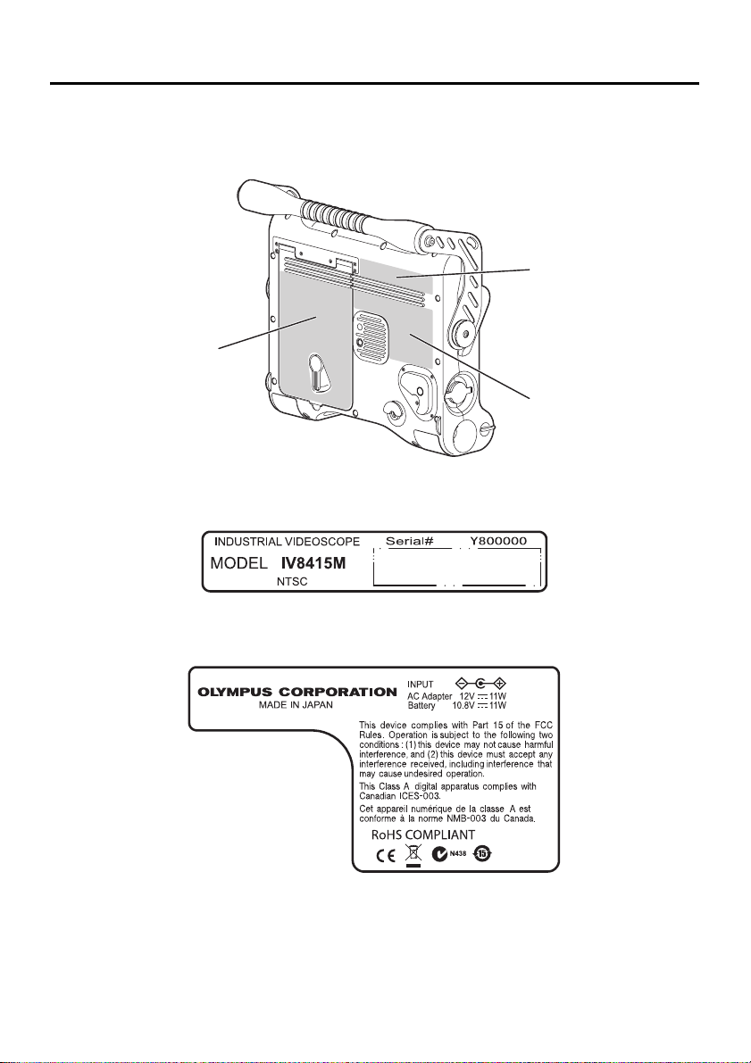
Warning and Rating Plates
Safety-related labels and symbols are attached to the instrument at the locations
shown below.
If labels or symbols are missing or illegible, please contact Olympus.
3. Warning plate
1. Rating plate A
1. Rating plate A
2. Rating plate B
2. Rating plate B
1
Page 8
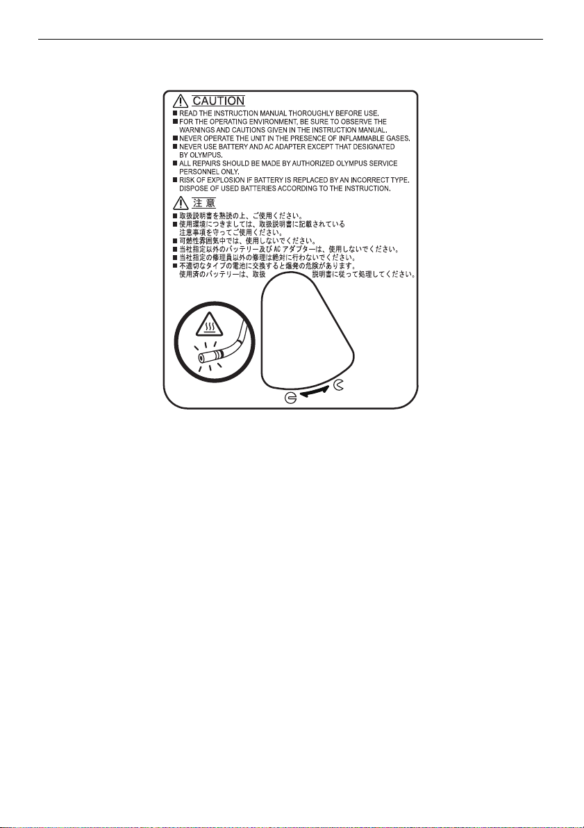
3. Warning plate
2
Page 9

Important Information – Please Read
Before Use
Intended use
This instrument has been designed to be used with IPLEX MX II series and
ancillary equipment for observation and examination of the insides of a
machinery, equipment or building that cannot be observed directly from the
outside.
Do not use this instrument for any purpose other than its intended use,
particularly for observation or examination of the inside of a human or animal
body cavity.
Instruction manual
This instruction manual contains essential information on using this instrument
safely and effectively.
Before use, thoroughly review this manual and the manuals of all equipment
which will be used during the procedure and use the equipment as instructed.
Keep this and all related instruction manuals in a safe, accessible location.
If you have any questions about any information in this manual, please contact
Olympus.
Combined ancillary equipment
Refer to the “System chart” page 90 in the Appendix to confirm that this
instrument is compatible with the ancillary equipment being used.
Using incompatible equipment can result in malfunction and/or equipment
damage.
Repair and modification
This instrument does not contain any user serviceable parts. Do not
disassemble, modify or attempt to repair. User injury and/or equipment damage
can result.
3
Page 10

Signal words
The following signal words are used throughout this manual.
DANGER
• Indicates an imminently hazardous situation which, if not avoided, will result in death or
serious injury.
WARNING
• Indicates a potentially hazardous situation which, if not avoided, could result in death or
serious injury.
CAUTION
• Indicates a potentially hazardous situation which, if not avoided, may result in minor or
moderate injury. It may also be used to alert against unsafe practices or potential equipment
damage.
NOTE
• Indicates additional helpful information.
Dangers, warnings and cautions
Follow the dangers, warnings and cautions described below when handling this
instrument. The information is to be supplemented by the dangers, warnings and
cautions given in each chapter.
DANGER
• Never use this instrument in observation inside the human and animal cavity. The human
body or animal may be injured.
WARNING
• Never use this instrument in a flammable atmosphere. Otherwise, an explosion or fire may
result.
• Do not use the instrument in an environment filled with fine particles such as metal dust.
• With the exception of the insertion tubes, this instrument and its case are not designed to be
waterproof. Except for the insertion tube, never use or store the instrument in any location
where it might be submerged in water. An electric shock may result.
• Never use this instrument on a piece of electrical equipment being energized. Since the
exterior finish of the insertion tube is electroconductive, an electric shock may occur if it is
brought in contact with an active part.
• Always turn the LIGHT button ( ) OFF when the instrument is not in use. Otherwise the
light emitted from the insertion tube may heat a nearby object and cause fire ignition.
• The distal end of the insertion tube may become hot due to the illumination light or the
internal heating caused by electrical parts. Touching the distal end immediately after having
turned off the light source may cause burn on your skin.
4
Page 11

• Do not allow the light emitted from the insertion tube’s distal end to enter your eye directly.
Otherwise, an eye injury may result.
• Should any abnormality be detected during angulation operation, do not continue the
angulation operation by force. Otherwise, the insertion tube or examination target may be
damaged.
• Do not subject the LCD surface to impact or strong pressure. Doing so could shatter the LCD
screen and cause personal injury.
• Do not rub the LCD with hard or sharp objects. This can crack or scratch the LCD panel.
• Do not allow a metallic object or a fluid such as water enter the battery compartment or the
battery terminals. Should any foreign object enter the instrument, remove the battery and the
AC adapter from the IPLEX MX II (main unit) and immediately contact Olympus.
• Do not touch the connectors directly by hand. Otherwise, a malfunction or electric shock may
result.
• Do not allow metallic or foreign objects to enter the device through connectors or any other
openings. Otherwise, a malfunction or electric shock may result.
• In case an irregularity such as smoke, abnormal odor or abnormal noise is detected,
immediately stop using the equipment even when it looks operable, and do not turn it ON
again.
• When transporting this equipment, turn off the power and remove the battery. It is extremely
dangerous to transport this equipment while it is on, as this can lead to unexpected
accidents.
CAUTION
• The image quality may be deteriorated in high temperature.
• Inserting the insertion tube into an observation object that is hotter than the operating
temperature may damage the equipment.
• Do not insert the insertion tube in a machine that is running, as this may result in the insertion
tube and/or machine damage. Also do not run the machine while the insertion tube is
inserted in it.
• The minimum bending radius of the insertion tube is 20 mm for the 4.4 mm type and 30 mm
for the 6 mm type. Bending at less than the minimum bending radius may result in damage to
the insertion tube.
• Do not bring the insertion tube in contact with a liquid other than water, saline, machine oil
and light oil. It may damage the instrument.
• Do not cover the instrument with a plastic bag or other object during use. If the inside of the
instrument cannot be cooled, the instrument damage may result.
• Do not use this instrument where it is exposed to direct sunlight.
• The LCD monitor may not display data normally when the instrument is used in an
environment where temperatures are below 0 °C. Use the instrument after using a heater to
bring the area to room temperature.
• Bringing the instrument indoor from cold atmosphere subjecting it to sudden temperature
change can cause condensation to form inside the instrument. Using the instrument while
condensation is formed creates the risk of malfunction. Wait until the instrument reaches the
same temperature as the room before using it.
• Never use the instrument in areas where strong radiation is present.
5
Page 12

• Do not remove the USB Flash Drive while playing back or recording still images. Otherwise,
the data recorded in the USB Flash Drive may be destroyed.
• Take care not to have your feet caught by a cord including the power cord or insertion tube.
• Do not pull the cable of the insertion tube, control unit or other equipment with a strong force.
Otherwise, the insertion tube or cable may be damaged or the instrument may topple down
or drop. Also, if the operator is using the shoulder strap, it may cause them to fall over.
• Do not pull main unit while holding the insertion tube, control unit or other cables.
• Do not operate the [ANGLE] joystick of the control unit with intensity while the angle lock is
on, otherwise it may cause malfunction.
• If the USB connector or other connectors become wet, wipe them dry.
Also, if any foreign matter gets into a connector, remove it.
• Accidentally dropping the IPLEX MX II (main unit) while cables or other device is attached to
a connector can damage the connector or the item that is attached to it.
• Never connect any other USB device or USB cable to the USB connector except for the USB
Flash Drive provided as standard or USB Flash Drive recommended by Olympus.
• Make sure that the battery cover, video connector cap, and AC adapter connector cap are
closed securely during storage or whenever connectors are not being used.
• Do not open the battery cover, video connector cap, AC adapter connector cap with wet
hands, or under damp or dusty environment.
• Never subject the IPLEX MX II unit to strong impact.
• The USB connector and the battery terminal on the main unit may get hot. Be careful to not
touch them when inserting or removing USB Flash Drive or the battery.
NOTE
• The images recorded with instrument can be displayed on a computer, etc., but it is not
possible to play back images recorded with an image recording device such as a digital
camera or a computer on the IPLEX MX II series instrument.
• Windows Media Player is either registered trademarks or trademarks of Microsoft Inc. in the
U.S. and/or other countries.
6
Page 13

Handling of the battery
Follow the dangers, warnings and cautions described below when handling the
battery. Otherwise, battery fluid leak, excessive heat generation, smoke, battery
burst, electric shock and/or burns may result.
DANGER
• In case of Li-ion operation, be sure to use the battery and battery charger designated for
IPLEX MX II series.
• Before use, thoroughly review the instruction manuals for the battery and battery charger to
fully understand the information contained in them, and observe their instructions during use.
• Do not install and use the battery by reversing the polarity. If the battery cannot be installed
properly in the instrument, do not attempt to insert it by force.
• Do not allow connectors to become shorted.
• Do not attempt to apply solder directly on a terminal. Otherwise, a hazardous situation such
as destruction of the terminal safety valve or scattering of battery fluid may result.
• Do not interconnect the electrodes of the battery through a metallic object or carry nor store
the battery together with a metallic object.
• Do not connect the battery directly to a power outlet or the cigar lighter of an automobile.
• Do not throw the battery in fire or heat the battery. Doing so creates the risk of explosion.
• Penetration of battery fluid in an eye may result in loss of eyesight. Should this occur, rinse
eyes thoroughly with clean water and immediately have a physician’s treatment.
• Do not attempt to open or modify the battery. Doing so creates the risk of explosion or fire.
• Do not immerse the battery in fresh or sea water, nor moisten the battery.
• Do not recharge the battery near a fire or under direct sunlight. Doing so creates the risk of
explosion or fire.
• Do not pierce the battery or subject it to strong impacts or load. Doing so creates the risk of
explosion or fire.
• Never drop or throw the battery, or subject it to strong impact.
• Place the equipment in a stable location to remove the battery. If the equipment is unstable,
the battery may fall out, which can lead to explosion and fire.
WARNING
• Do not use a battery that is not recommended for IPLEX MX II series.
• Do not attempt to recharge a battery that is not designated for IPLEX MX II series.
• If the battery charger cannot complete battery charging in the specified recharging time, stop
trying to recharge the battery.
• Do not use a battery if it presents an irregularity such as fluid leak, discoloration, deformation
or abnormal condition. Immediately request servicing.
• If the battery fluid attaches to your skin or clothes, immediately rinse with clean water such as
tap water. Otherwise, a skin injury may result. Contact a physician for treatment if necessary.
• Do not deform the battery compartment or put a foreign object in it.
• Do not cover the battery charger and battery with clothes or cushion during recharging. Also
avoid any situation in which the covering of the battery charger and battery by such objects is
expectable.
7
Page 14

CAUTION
• Do not soak the battery in or moisten it with water including rainwater and seawater.
• Do not leave the battery in a place subject to moisture, water leak or extremely high or low
temperatures.
• Do not touch the battery terminals with a wet hand.
• Be sure to recharge the battery before using them for the first time after purchase or after
they have not been used for a long period.
• When the battery is not to be used for a long period, be sure to remove them from the IPLEX
MX II (main unit). Otherwise, battery fluid leak and heat build-up may result in a fire or injury.
• Do not use or leave the battery in a place with high temperature, for example under direct
sunlight, in a closed automobile under the sun or in front of heating equipment.
• The battery is hot after long hours of operation of IPLEX MX II series. Do not take out the
battery immediately after use, as this may result in burning your hand.
• Do not leave the battery in the reach of children.
• When replacing the battery, do not repeatedly remove and load the battery rapidly. Doing so
may make it impossible to turn on power.
NOTE
• Use the battery correctly, as incorrect use may result in fluid leak, excessive heat generation
and/or damage. When replacing the battery, install them correctly by observing the insertion
direction.
• In general, the battery performance drops as the ambient temperature drops. Note that the
battery performance degraded due to low temperatures recovers when the temperature rises
to a normal level.
• Contamination of battery electrodes with sweat or oil will cause contact failures. When the
battery is dirty, wipe it clean with a dry cloth before use.
• The continuous operating time of the IPLEX MX II series time with a fully charged battery
condition is approx. 120 min. (fully-charged new battery). When long hours of batterypowered operation are expected, it is recommended to prepare charged batteries as spares.
• The battery is designated as a recyclable product. When discontinuing the use of the battery,
be sure to have it recycled in compliance with your local regulations.
• Recommended temperature range for Li-ion battery operation.
Discharge (when using the instrument): 0°C to 40°C
Recharging : 0°C to 40°C
Storage : -20°C to +50°C
Using the battery under a temperature outside the above temperature range will result in
degradation of the performance and service life. When storing the battery, be sure to remove
it from the IPLEX MX II (main unit).
• The battery is a consumable item.
• The battery cannot be charged using the equipment. For information on charging the battery,
refer to the manual that came with the battery charger.
8
Page 15

Product configurations of the IPLEX MX II series
The IPLEX MX II series includes a main unit, control unit, and an insertion tube
as shown in the table below.
The simplified specifications of the insertion tubes are shown below.
For detailed specifications of the individual models, see “Chapter 9
Specifications” (page 81).
IPLEX MX II series
model names
IV8415M
IV8430M
IV8630M φ 6.0 mm
Max. insertion tube
outer diameter
φ 4.4 mm
Insertion tube length
1.5 m
3 m
Refer to the “System chart” in the Appendix for the IPLEX MX II and optional
equipment configurations.
9
Page 16

Chapter 1
Checking the package contents
1.1 Checking the package contents
Match all items in the package with the components shown on “IPLEX MX II
series package contents” below. If any item is damaged, a component is missing
or you have any questions, do not use the instrument, but immediately contact
Olympus.
IPLEX MX II series package contents
Name Count
IPLEX MX II (main unit) 1
USB Flash Drive 1
AC adapter 1
AC power cord *1 *
IPLEX MX II Utility Disc (IPLEX VIEWER PLUS) 1
Shoulder strap 1
Lens cleaning kit (cleaning fluid, cotton swab) 1
Insertion tube holder 1
10
Insertion tube wrap belt 1
LCD protection sheet (Stuck to the LCD monitor) 1
Instruction Manual IPLEX MX II series (This booklet) 1
IPLEX MX II Operation manual 1
AC adapter 1
IPLEX MX II utility disc 1
Software license agreement 1
LCD protection sheet 1
Carrying case 1
* For a PAL configuration set, 2 power cables, each with a different plug type, are
provided.
Page 17
Chapter 2
Instrument nomenclature and
functions
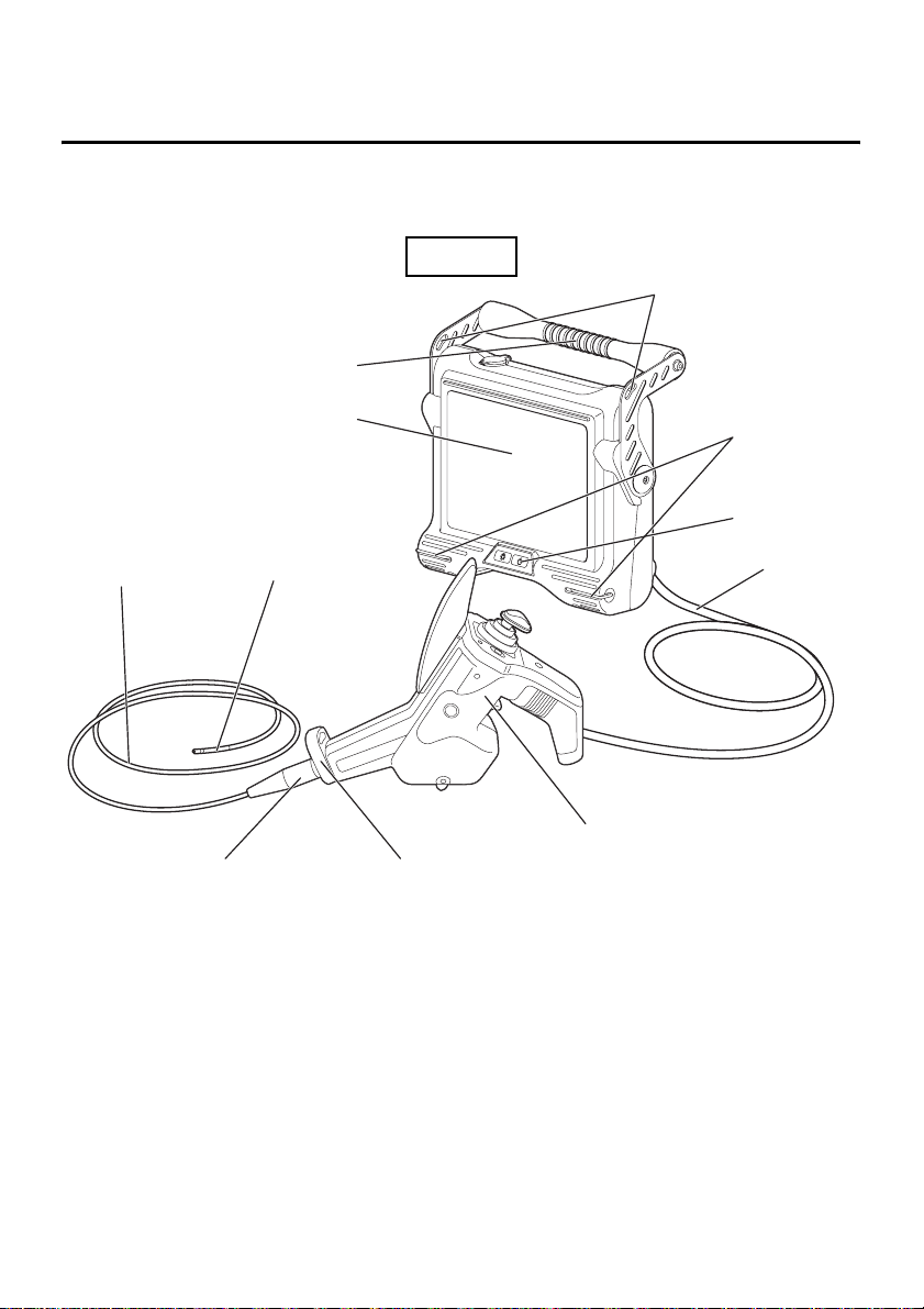
2.1 System nomenclature
Main unit
Handle
Strap holder
Insertion tube
LCD monitor
(covered by LCD
protection sheet)
Angulation section
Bend stopper
Strap holder
Front panel
Universal
cable
Control unit
Insertion tube holder
11
Page 18
Chapter 2 Instrument nomenclature and functions
12
Shoulder strap
Insertion tube wrap belt
Page 19
Chapter 2 Instrument nomenclature and functions
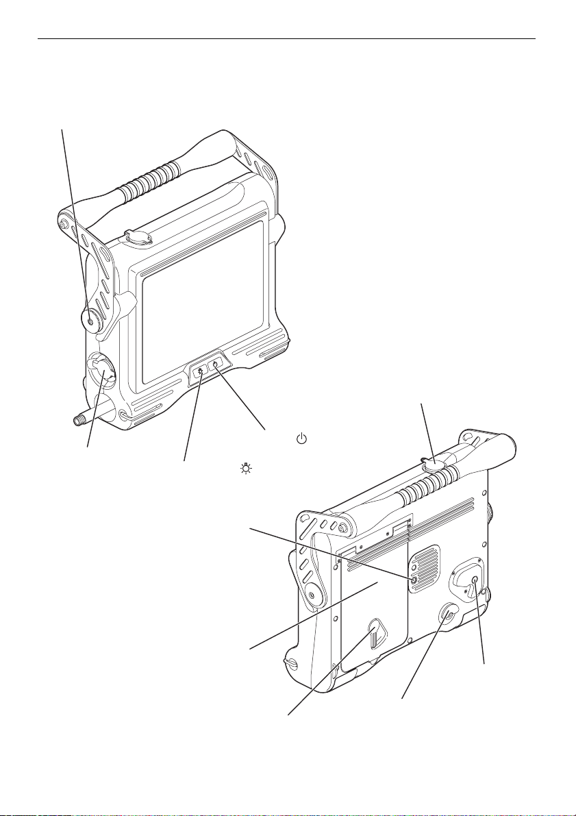
2.2 Main unit nomenclature and functions
Control unit holder
Video connector cap
AC adapter
connector cap
POWER button ( )
LIGHT button ( )
Tripod screw thread
Battery cover
Lock release button
Scope handset holder
Lock release lever
13
Page 20
Chapter 2 Instrument nomenclature and functions
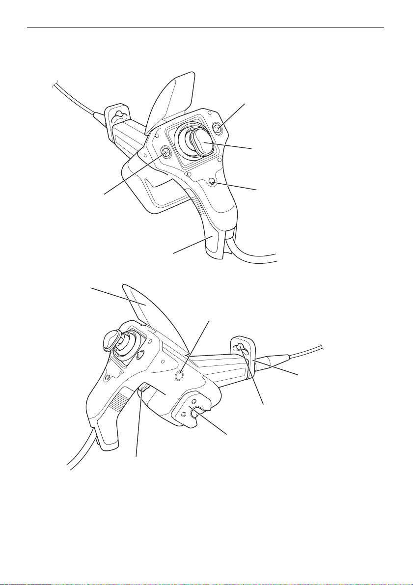
2.3 Control unit nomenclature and functions
[ZOOM] lever
Zooming the image/Menu selection/
Retrieved image selection
[ANGLE] joystick
Angulation operation
[BRT] lever
Adjusting the brightness/
Menu selection/
Retrieved image selection
Joystick guard
Grip
[FRZ/REC] button (two locations; left and right)
Freeze/record observed image/live image display
[ANGLE LOCK] lever
To lock the angulation operation
[VIEW/MENU] button
Retrieve screen display/
Menu display
Insertion tube holder
Hole to hold insertion tube
Secures the insertion tube
Hanger
To hang the control unit
on the main unit
14
Page 21
Chapter 2 Instrument nomenclature and functions
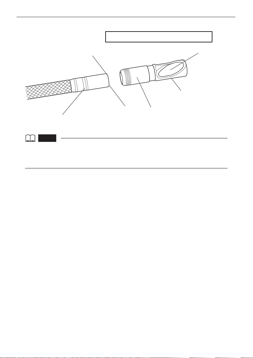
Side view mirror adapter: 6-mm type (optional)
Objective lens
Side view mirror
adapter lock groove
Illumination
Nut
Mirror
Product abbreviation
(50S V7X2)
NOTE
• The insertion tube can temporarily be fixed on the control unit by inserting it into the insertion
tube holder hole.
• The insertion tube holder can be rotated or removed.
15
Page 22
Chapter 3
Preparation and inspection
before observation
CAUTION
• Be sure to finish the preparation and inspection work described below before use. If any
irregularity is suspected, do not use the instrument but see “Chapter 8 Troubleshooting”
(page 75) to solve the problem. If irregularity is still suspected, contact Olympus. Damage or
irregularity may compromise the correct functioning of the instrument and may result in more
severe damage to the examined subject.
• Inspections are not only required before use, but should be conducted periodically.
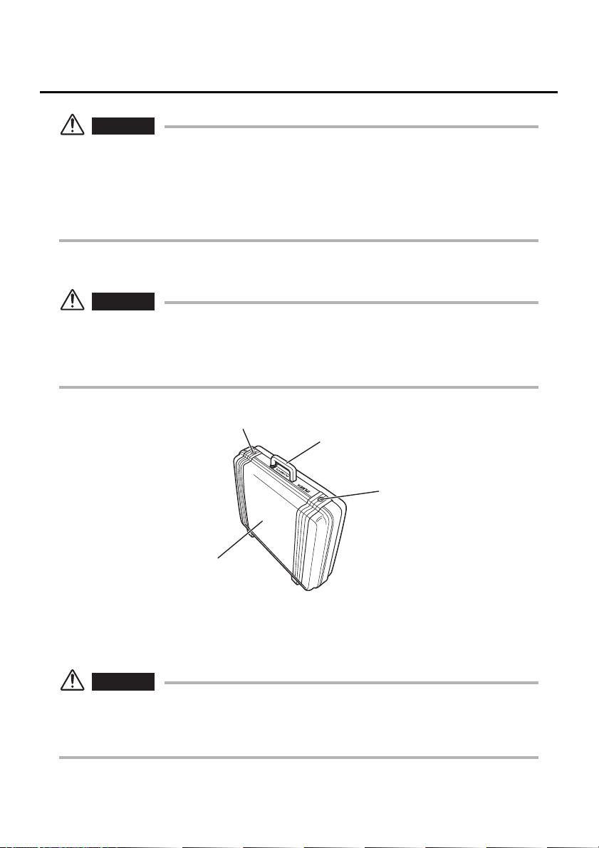
3.1 Transportation of the case
CAUTION
• Before transporting the case, inspect the exterior parts handles and latch of the case for
irregularities such as damage and loosening.
• Use only the designated case. Failure to do so may cause damage or malfunction of the
insertion tube and/or main unit.
Latch
Top cover
Handle
Latch
When using the handle
1 Ensure that the latch is closed firmly before lifting the case.
CAUTION
• Never move the equipment around by the insertion tube or cables.
If the latch is not completely closed, the top cover may open accidentally when the case is lifted.
•
• Do not kick the case or move it with your feet.
16
Page 23
Chapter 3 Preparation and inspection before observation
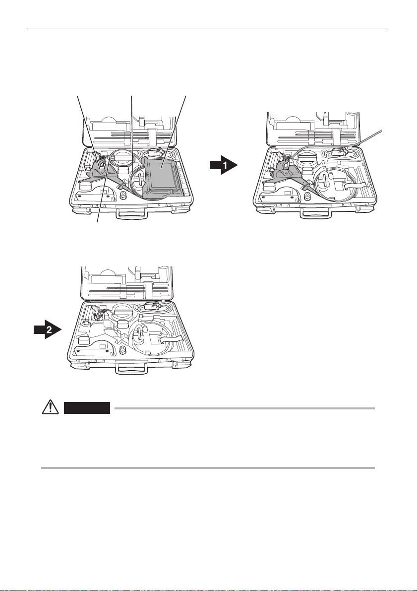
Taking the instrument out of the case
Remove the equipment in the order of: Main unit → Insertion tube →
Control unit.
Control unit
Universal cable
Insertion tube
Main unit
Remove the main unit.
Remove the control unit and insertion tube.
WARNING
• Fully open the top cover when removing the main unit from the case. If the cover is not fully
open, it can close unexpectedly and pinch your hand or cables.
• Never use the main unit while it is accommodated inside the case. If the top cover of the case
is left open, it may close unexpectedly and pinch your hand or a cable.
17
Page 24

Chapter 3 Preparation and inspection before observation
CAUTION
• Place the case on a level surface so it is stable.
• To open the top cover of the case, release the latch on the front of the case.
• Do not pull the insertion tube with excessive force when taking it out of the cushioned slot.
Otherwise, the insertion tube may be damaged.
• When taking the control unit or main unit out of the case, never hold them by the insertion
tube or universal cable. It may damage the instrument.
• Check if the insertion tube, battery cover, video connector cap and adapter connector cap are
kept clean. Wipe off with a clean, soft cloth if dirt or a foreign substance is attached.
• Check the insertion tube, battery cover, video connector cap and adapter connector cap if
cuts or gaps are not available.
18
Page 25
Chapter 3 Preparation and inspection before observation
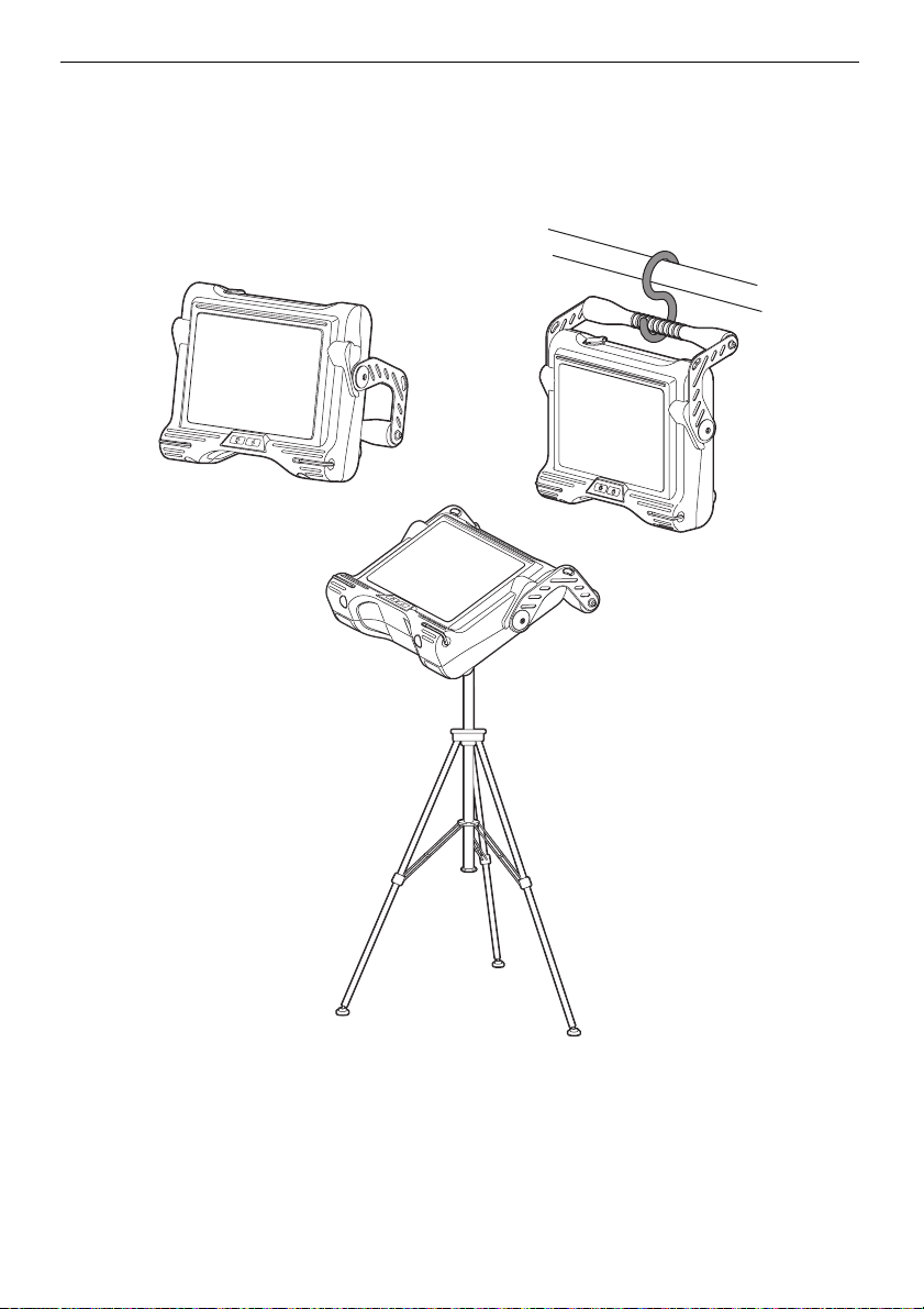
3.2 Setting up the main unit
1 The main unit can be used in any one of the three setup
configurations shown below.
Use the handle
as a stand
Put it on a tripod
Hang it from
the handle
19
Page 26
Chapter 3 Preparation and inspection before observation
CAUTION
• Place the main unit on a level surface so it is stable. The main unit can tip over if it is not
stable.
• Do not place the main unit in overhead location. Doing so may result in the main unit falling
and being damaged.
• When suspending the base unit while using it, hook the handle someplace that can support
its weight and where there is no danger of it falling.
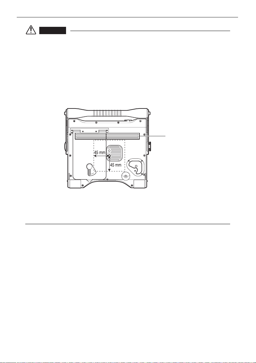
• When mounting the tripod to the main unit, install it so the tripod platform does not run up on
the protrusion on the rear of the main unit. Affixing the tripod with the platform installed at an
angle can cause the main unit to fall off. You can use a platform with a size that is less than
45 mm from the center of the tripod screw.
Protrusion
• Setup the tripod on level ground. Setting the tripod up on a slope or uneven ground is
dangerous because it may fall over.
• Be careful not to accidently move the lock release lever on the battery cover and open it
when handling the main unit.
20
Page 27
Chapter 3 Preparation and inspection before observation
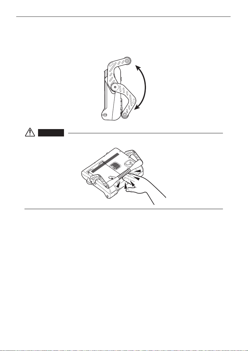
Using the handle
The handle can be lowered from its storage position and freely adjusted within
the range shown in the illustration below. When using the handle as a stand, you
can adjust the angle for easy viewing.
CAUTION
• Take care not to pinch your hand or other objects when moving the handle.
21
Page 28
Chapter 3 Preparation and inspection before observation
3.3 Preparing the power supply
WARNING
• Do not bend, pull, twist, crush or apply excessive force to the power cord of the AC adapter.
Otherwise, a break in the power cord wires may cause a fire or electric shock.
• Ensure that the power cord is normal before connecting it. Using a power cord with
irregularities may result in an electric shock.
• Be careful not to injury yourself when replacing the battery.
CAUTION
• Be careful not to accidentally drop the battery during replacement.
• Before using the battery, read the dangers, warnings and cautions in “Handling of the battery”
under “Important Information – Please Read Before Use” on (page 7).
• The battery indicator flashes when a battery is continuously used under low-voltage
conditions. In such case immediately turn off the power of the main unit or connect the AC
adapter. If continuously used without any action the power will be automatically turned off
which may cause malfunction.
• Do not remove AC adapter or battery while the system is running. It may cause malfunction.
Supplying power from the battery
1 Check to make sure that main unit power is turned off.
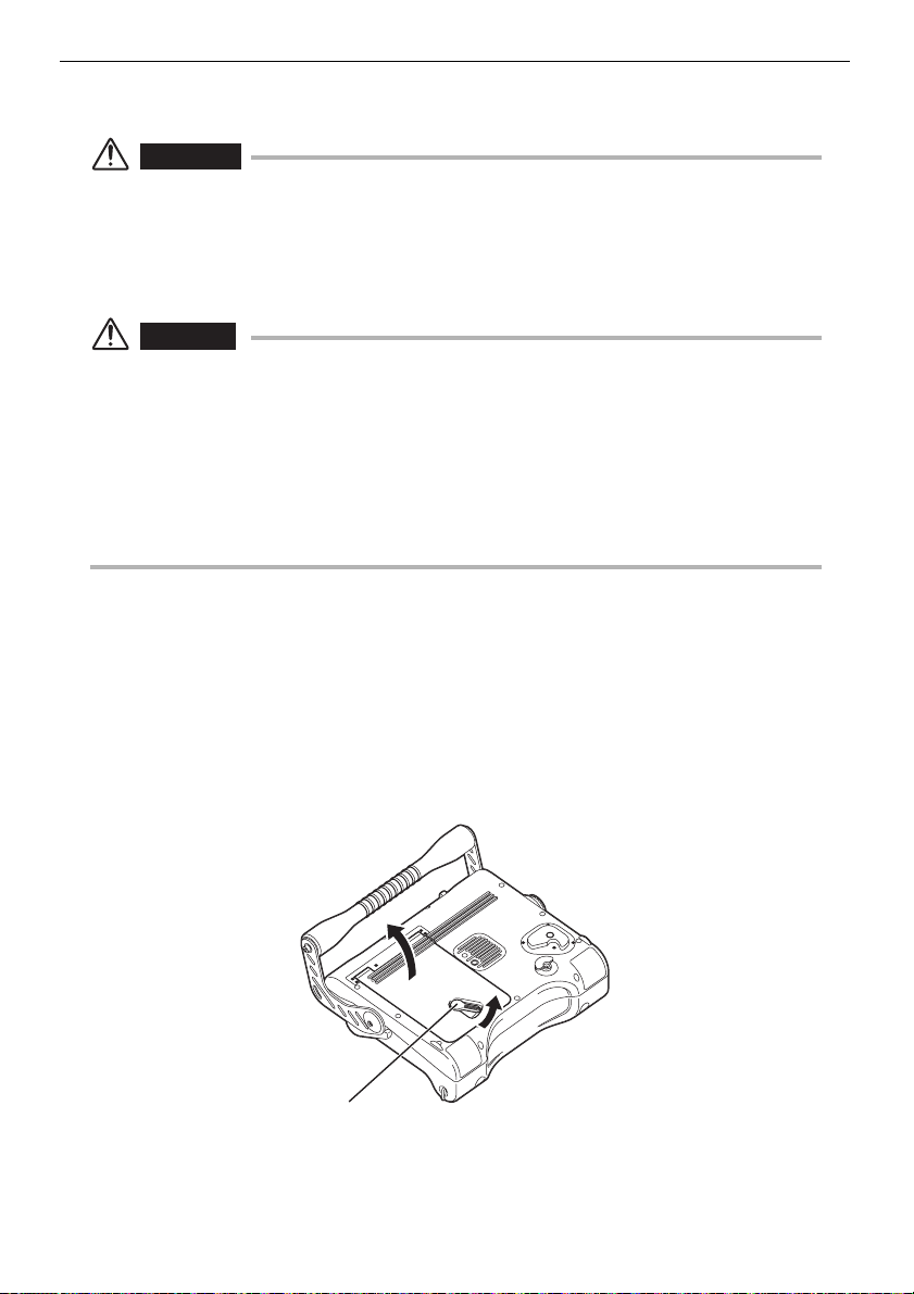
2 Return the handle to its storage position.
3 Move the lock release lever on the battery cover as shown in the
figure below to open the battery cover.
Lock release lever
22
Page 29
Chapter 3 Preparation and inspection before observation
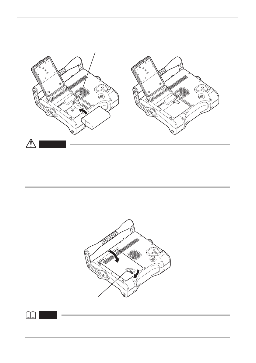
4 Insert the battery so that the ribbon passes under it. This is so you
can pull the ribbon to remove the battery.
Ribbon
CAUTION
• When loading the battery, check to make sure the main unit’s battery contacts and the
battery terminals are positioned correctly.
• Never try to force the battery if it does not slide in easily. Check to make sure that the battery
is positioned correctly and that there is no problem with its terminals. Trying to force the
battery in may cause malfunction.
5 Close the battery cover and move the lock release lever on the
battery cover as shown in the figure below to lock it.
Lock release lever
NOTE
• If you are having trouble locking the battery cover, press on the cover while moving the lock
release lever.
23
Page 30
Chapter 3 Preparation and inspection before observation
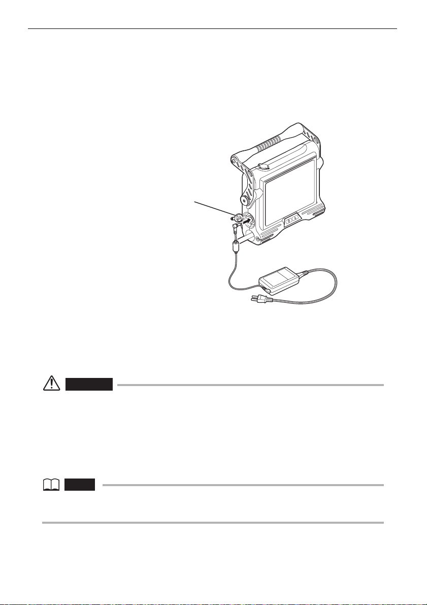
Supplying power from the AC adapter
1 Open the AC adapter connector cap.
2 Connect the AC adapter to the AC adapter connector on the main
unit.
AC adapter connector cap
3 Ensure that the AC power cord is connected securely to the AC
inlet of the AC power adapter.
4 Plug the AC power cord securely into a power outlet.
WARNING
• Inspect the power cord before use and check for any signs of damage. Using a power cord
with irregularities may result in an electric shock.
• Uses AC power code appropriate for the standard AC power in the country that uses it.
• Never use an AC adapter other than the designated AC adapter. Otherwise, malfunction of
the instrument or unexpected damage may result.
• The AC adapter is not water resistant. Never use it in the rain or in any location where it can
become wet. Water creates the risk of electric shock.
NOTE
• For information about how to connect the AC adapter, see the AC adapter’s instruction
manual.
24
Page 31

Chapter 3 Preparation and inspection before observation
3.4 Inspecting the insertion tube
CAUTION
• Be sure to hold the insertion tube by a position on the rear of the angulation section.
Otherwise, the angulation section may be damaged.
Inspecting the external appearance of the insertion tube
1 Check visually that the external finish of the complete length of the
insertion tube and universal cable are free of irregularities such as
deformation.
2 Check that the external covering material of the insertion tube,
other than the angulation section, is not loose.
CAUTION
• If the insertion tube is deformed, you may not be able to withdraw it from the observation
object.
• If the external material of the insertion tube is cut, take care against injury during inspection.
Inspecting the insertion tube distal end
WARNING
• The distal end of the insertion tube may become hot due to the illumination light or the
internal heating caused by electrical parts. Touching the distal end immediately after having
turned off light source may cause burn on your skin.
1 Make sure that power is turned off.
2 If the side view mirror adapter is attached to the insertion tube, turn
the nut counter-clockwise to detach the side view mirror adapter
from the insertion tube (see “Attaching and detaching the side view
mirror adapter” (page 28)).
25
Page 32

Chapter 3 Preparation and inspection before observation
3 Check that there is no dirt or water on the insertion tube distal end.
If dust or water is present, wipe them clean with a soft piece of
gauze or a cotton swab, grasping at hard part of distal end. The
best results may be obtained using the lens cleaning fluid provided
in the lens cleaning kit.
4 Check that the distal end of the insertion tube is not deformed or
loose.
CAUTION
• Never use the distal end of the insertion tube if any part is loose. Otherwise, the loose part
may fall into the inspection object.
• The angulation section is composed of precision parts. Do not pull the distal end of the
insertion tube, do not grasp/bend with a strong force. Otherwise, the parts in the angulation
section may be damaged.
26
Page 33

Chapter 3 Preparation and inspection before observation
3.5 Inspecting the side view mirror adapter (optional) (for IV8630M)
WARNING
• The distal end of the insertion tube may become hot due to the illumination light or the
internal heating caused by electrical parts. Do not forget to turn off the light source before
attaching or detaching the side view mirror adapter. Touching the distal end immediately after
having turned off light source may cause burn on your skin.
Checking the side view mirror adapter and connection
screws
1 Inspect the mirror surface of the side-view mirror adapter for
contamination. If it is stained, wipe the stain completely away using
the provided lens cleaning kit. When wiping the mirror surface
without removing the adapter from the insertion tube, hold the
combination by the rigid section of the insertion tube.
CAUTION
• The mirror surface of the side-view mirror adapter may be damaged if it is wiped dry. When
removing the stain from the mirror surface, be sure to use the lens cleaning kit provided with
the insertion tube. Also remember that the mirror surface may be damaged if a liquid other
than water or the lens cleaning fluid is attached on the mirror surface.
• The mirror surface of the side-view mirror adapter may be damaged during removal of
metallic powder, sand or mud attached on it. If the mirror surface is contaminated with these
objects, remove the side-view mirror adapter from the insertion tube and wash the objects
away under running water.
• If the mirror surface of the side-view mirror adapter is still stained after it has been wiped
using the lens cleaning kit provided with the insertion tube, do not attempt to force remove
the stain but contact Olympus.
27
Page 34

Chapter 3 Preparation and inspection before observation
2 Check the bores connection diameters of the side of the insertion
tube distal end, side view mirror adapter lock groove and side view
mirror adapter, and that their screws are not deformed or have
foreign objects attached to them.
Attaching and detaching the side view mirror adapter
CAUTION
• If the side view mirror adapter cannot be attached or detached because its nut will not turn,
stop using the equipment and contact Olympus.
• The side view mirror adapter is a precision instrument using glass mirrors in the optics. Be
careful not to drop it or apply a strong impact to it.
• The mirror surface of the side viewing mirror adapter is an optical component. It is
susceptible to stains and scratches.
• Do not attempt to insert the insertion tube into the side view mirror adapter by force.
Otherwise, it would become impossible to withdraw the insertion tube later.
NOTE
• If the side view mirror adapter cannot be clamped completely by tightening the nut, the
threads may be contaminated. Apply the provided cleaning fluid on the inner side of the nut
of the side view mirror adapter and turn the nut. This will clean the threads and makes it
possible to clamp the side view mirror adapter completely.
• If the threads are extremely dirty or the claw inside the side view mirror adapter is
contaminated, remove the nut from the side view mirror adapter and clean it.
1 When inserting the insertion tube’s distal end into the side view
mirror adapter, set the nut so that the red index is visible entirely.
Nut
Red index
28
Page 35

Chapter 3 Preparation and inspection before observation
CAUTION
• Do not use the side view mirror adapter with the green index. They cannot be attached
correctly.
• If the red index is not completely visible, you cannot insert the distal end of the insertion tube
into or remove it from the side view mirror adapter.
• The nut will fall off the mirror if it is loosened any further after the red index is completely
visible (see below). If the nut comes off, it may be lost or the claws may be damaged. Do not
remove the nut except to clean the inside of the side view mirror adapter.
Mirror section
2 Slowly insert the insertion tube distal end into the side view mirror
adapter and push in till the claw inside the side view mirror adapter
is engaged with the claw on the insertion tube distal end (this
determines the rotation direction). If the side view mirror adapter
cannot be inserted, rotate it so that its mirror turns and ensure that
it is fit properly. Turn the screw clockwise until it becomes loose
and confirm that the red index gets hidden.
3 Rotate the side view mirror adapter while lightly pushing it, and
confirm that the rotation is stopped by engagement of the claw
inside the side view mirror adapter in the mirror adapter lock
groove on the insertion tube distal end.
29
Page 36

Chapter 3 Preparation and inspection before observation
4 Lightly push the side view mirror adapter clockwise onto the
insertion tube so that the second threaded section is engaged.
Tighten the nut all the way until it is stopped. Make sure that the
side view mirror adapter is securely attached.
5 To detach the side view mirror adapter, reverse the attaching
procedure.
Inspecting the parts of the side view mirror adapter
Check that the parts of the side view mirror adapter are not loosened.
CAUTION
• Never use it if any parts are loose. Otherwise, the loose part may fall into the inspection
object.
30
Page 37

Chapter 3 Preparation and inspection before observation
3.6 Inspecting the control unit and the universal cable
1 Check for irregularities such as damage or deformation to the
external material, buttons, joysticks, and levers.
2 Ensure that the universal cable is free of irregularities such as cuts
and buckling.
[BRT] lever
[VIEW/MENU] button
Universal cable
[ANGLE] joystick
[ZOOM] lever
[FRZ/REC] button
(two locations; left and right)
[ANGLE LOCK] lever
31
Page 38

Chapter 3 Preparation and inspection before observation
3.7 Inspecting the LCD monitor
Inspecting the external appearance
1 Check that the LCD monitor is free of irregularities such as cracks
on the screen.
NOTE
• The LCD panel is fabricated based on precision technologies. The LCD panel may contain
pixels that do not light (visible as black dots) or light permanently (visible as bright dots), but
this is not a defect or malfunction of the product.
• To clean the LCD monitor if it is dirty or has fingerprints on it, see “Cleaning the LCD monitor”
(page 69).
32
Page 39

Chapter 3 Preparation and inspection before observation
3.8 Mounting of the control unit on the main unit
The control unit can be attached to the main unit as desired. It can be attached
to the main unit for carrying and left attached to the main unit during observation.
Handle
Back attachment: For transport Side attachment: For observation
1 Insert the hanger on the side of the control unit straight into the
control unit holder on the side or the back of the main unit. The
hanger may not fit correctly at an angle into the control unit holder,
be sure to put it straight into the control unit holder.
Hanger
Control unit holder (side)
Control unit holder (rear)
Lock release button
33
Page 40

Chapter 3 Preparation and inspection before observation
2 When attaching the control unit to the back of the main unit, check
that it is positioned as shown in the figure below before attachment.
Then, check that the control unit is firmly attached. Attaching it with
excessive force in the wrong direction can cause the control unit to
fall off and cause an accident. This also may damage the main unit.
Correct direction
Incorrect direction Incorrect direction
3 Push in the hanger until you feel a click. If it is not inserted
completely it may come off too easily.
4 When detaching the control unit from the main unit, pull the control
unit straight upward from the main unit. When the control unit is
affixed to the back of the main unit, hold down the center of the lock
release button as you pull upwards.
34
Page 41

Chapter 3 Preparation and inspection before observation
CAUTION
• Hold the handle of the main unit when transporting the main unit with the control unit affixed
to the back. The main unit may fall or the excessive force to the main unit may damage
connections if you lift it by the control unit.
• Take care not to tilt or swing the main unit when carrying it with the control unit attached. Doing
so can cause the control unit to fall off and cause unforeseen accidents or personal injury.
• When transporting it with the control unit and main unit affixed to each other, take care so the
universal cable and insertion tube do not come into direct contact with the ground. A dangling
universal cable or insertion tube can become entangled with your feet causing you to fall,
which may cause personal injury, damage to this equipment, and malfunction.
• When putting down the main unit while the control unit is attached to it, always place it on its
side or base. Otherwise, the control unit and/or insertion tube may be damaged.
• Do not use excessive force or twist the control unit when it is attached to the main unit. Doing
so may damage the hanger.
35
Page 42

Chapter 3 Preparation and inspection before observation
3.9 Attaching and detaching the strap
When you want to hang the IPLEX MX II (main unit) from your shoulder, attach
the shoulder strap. Be careful not to use a shoulder strap other than those
designated by Olympus and supplied with the IPLEX MX II unit.
WARNING
• Never attempt to carry an object other than the IPLEX MX II (main unit) using the shoulder
strap. Otherwise, the strap may be damaged and cause the IPLEX MX II (main unit) to drop.
• Be sure to check that the shoulder strap is free of irregularities such as frayed fibers and
damaged metal parts before use.
• Do not use the shoulder strap in a manner that is subjected to an excessive load by, for
example, swinging the IPLEX MX II (main unit) or placing a heavy object on the instrument.
• When using the shoulder strap, be careful not to hit the IPLEX MX II (main unit) against other objects.
• When using the shoulder strap, be careful not to bring it in direct contact with your skin. Otherwise,
there will be a risk of low-temperature burns on your skin due to the heat of the instrument may result.
CAUTION
• Be careful to not drop the IPLEX MX II (main unit) when attaching or removing the shoulder strap.
• Do not put the main unit into the carrying case with the shoulder strap attached. Doing so
may damage the LCD monitor or the shoulder strap.
• Do not store the IPLEX MX II (main unit) by hanging it from something. Otherwise, the strap
may be damaged.
• Check to make sure that the shoulder strap hooks are fixed securely to the main unit. If they
are not, the main unit can drop when picked by the shoulder strap.
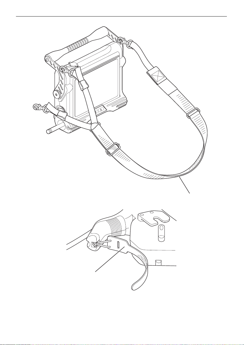
Attaching the strap
1 While pressing the shoulder strap hook lever, attach the hook to a
main unit strap ring or the strap bracket.
Strap ring
Strap bracket
36
Page 43

Chapter 3 Preparation and inspection before observation
Two strap rings are provided for attaching the strap when
transporting the main unit. Attach the strap to the two strap
brackets and to one of the strap rings to do observations.
During observation, attach the shoulder strap so that the side with
the two connections is on the left side of the main unit, as shown in
the figure below. The two connections can also be attached to the
right side of the main unit. However, this will be unbalanced and
operation may be difficult when the control unit is attached to the
side of the main unit.
Not attached
For transport For observation
2 Adjust the length of the shoulder strap using its length adjuster.
Length adjuster
37
Page 44

Chapter 3 Preparation and inspection before observation
3 Use the length adjusters shown below to adjust the angle for easy
viewing during observations.
Length adjuster
4 Use the shoulder strap to hang the IPLEX MX II (main unit) from
your shoulder.
38
For observationFor transport
Page 45

Chapter 3 Preparation and inspection before observation
5 While walking with the control unit attached to the main unit (back,
left side), insert the slack of the universal cable between the handle
and the main unit. If the universal cable is dangling while you are
walking, you may trip on it or have an accident.
Universal cable
6 You can use the insertion tube wrap belt on the control unit to
secure the insertion tube.
Removing the strap
To remove the strap, press the hook lever of the shoulder strap as you unhook
the strap from the main unit strap ring or strap bracket.
39
Page 46

Chapter 4
Basic operations
4.1 Turning on the power
Turning the power on
1 Hold down the main unit’s power button ( ) for at least two
seconds and confirm that the power turns on.
Power button ( )
Turning off the power
Press and hold the power button ( ) on the main unit for 2 seconds.
NOTE
• The power turns off about 3 seconds after pressing the power button ( ).
40
Page 47

Chapter 4 Basic operations
Checking the LCD monitor image
1 Ensure that the LCD monitor displays the observation image.
2 Make sure there are no dark patches or dirt in the image. If you find
any irregularities, go back to “3.4 Inspecting the insertion tube”
(page 25) to check it again.
NOTE
• The screen displays and menu operations are enabled approximately 40 seconds after the
power button ( ) is pressed.
• When the language setting is changed, the time taken until the screen display functions, such
as menu selection, may be longer than before. This is not a malfunction.
• The displayed title is the title that was entered on the Live screen the last time the system
was used.
Indicator display
Recording/playback indicator
Brightness level
Zoom level
Date/time Title
Display language setting
Select the language to be used for menus and other display text before using
the system for the first time. For more information, see “Language selection”
(page 62).
Freeze indicator
Battery indicator
Light indicator
Logo
41
Page 48

Chapter 4 Basic operations
Date and time settings
Set the current date and time before using the system for the first time. For more
information, see “Setting the date and time” (page 60).
Checking the illumination lighting
WARNING
• The Illumination emitted from the insertion tube distal end may heat and ignite a nearby
object. Be sure to set the illumination light turn off the LIGHT button ( ) on the front panel of
the main unit when not using the instrument.
• Do not allow the light emitted from the insertion tube’s distal end enter your eye directly.
Otherwise, an eye injury may result.
1 Confirm that the light indicator is shown on the screen. If it is not,
press the LIGHT button ( ) on the front panel to make it appear.
2 Verify the light is emitted from the insertion tube to ensure that the
light source is turned on.
White balance adjustment
Adjust the white balance of the insertion tube as required by following the
procedure described in “Live screen/frozen screen menu display and functions”
in “WHITE BALANCE” (page 57).
Checking the angulation functions
1 Straighten the insertion tube.
2 Manipulate the [ANGLE] joystick slowly and ensure that the
angulation section moves smoothly.
CAUTION
• Repair is required if the joystick shaft is bent or if the knob is detached. Contact Olympus.
NOTE
• The angulation movement is interlocked with the angle and direction of the [ANGLE] joystick
movements.
42
Page 49

Chapter 4 Basic operations
Checking the angulation lock
1 Pull the [ANGLE LOCK] lever up until it clicks. Confirm that
angulation remains locked even when you remove your finger from
the [ANGLE] joystick.
2 Pull the [ANGLE LOCK] lever up until it clicks again to confirm the
angle lock is released.
Every time the [ANGLE LOCK] lever is pulled up and clicks, it changes from
locked to unlocked and vise versa.
CAUTION
• Do not use the [ANGLE] joystick while the angle lock is on. Otherwise it may cause an
overload malfunction.
• A red mark is visible on the side of the [ANGLE LOCK] lever when the angle lock is on. If the
articulation feels restricted or heavy to operate, check whether the angle lock is on or not.
43
Page 50

Chapter 4 Basic operations
4.2 Inserting the insertion tube
Holding the control unit and insertion tube
1 In general, the [ANGLE] joystick of the control unit is manipulated
with the thumb of the hand holding the grip of the control unit.
2 Other buttons are also to be manipulated with the fingers of the
hand holding the grip of the control unit.
3 Hold the insertion tube with the other hand to which the control unit
is being held.
44
Page 51

Chapter 4 Basic operations
Inserting the insertion tube
While observing the monitor screen, carefully check the insertion direction as
you slowly insert the insertion tube into the object being observed. Perform the
angulation operation as required during insertion. Be careful not to apply
excessive pushing force, twisting or tension to the insertion tube.
WARNING
• Be sure to turn the illumination light on during insertion into the object being examined.
• If, after the side view mirror adapter is attached to the IV8630M, the overall observation
image is oriented to the left or right as shown in the figure below, or the image rotates or
fluctuates while the insertion tube is moved, the side view mirror may be about to be
detached from the insertion tube distal end. As continuing the use may cause the side view
mirror adapter to drop from the insertion tube, immediately stop using the insertion tube,
withdraw it gently and reattach the side view mirror adapter securely as described in the
attaching procedure.
• Read and understand the contents of “Important Information – Please Read Before Use”
(page 3) before using the insertion tube. In case of any questions, contact Olympus.
CAUTION
• Using the system under any conditions other than those specified in “Operating Environment”
in “Chapter 9 Specifications” (page 81) in the instruction manual may cause unexpected
accidents that may damage the insertion tube.
• The amount of screen noise may increase under high ambient temperatures.
• If any irregularities are found with the insertion tube operation or other things during the
insertion tube insertion, do not insert the insertion tube any further. If this happens, (release
the angulation lock if it is locked) remove your finger from the [ANGLE] joystick, return the
angulation section to center position and slowly remove the insertion tube.
45
Page 52

Chapter 4 Basic operations
Angulation operation
1 The insertion tube should be angulated as required for guidance or
observation. See “Checking the angulation functions” (page 42) for
details about angulation operation.
NOTE
• Increasing the insertion tube looping amount (bending amount) decreases the maximum
angulation angle limit of the angulation section. Keep the insertion tube as straight as
possible to get the best operation from the instrument.
• Angulation tends to be difficult to achieve under low temperatures.
• Do not withdraw the insertion tube while its angulation is locked or while your finger is on the
[ANGLE] joystick. Doing so can damage the insertion tube and/or object being observed.
• Should any abnormality be detected during an angulation operation, do not try and force the
angulation operation to continue. Doing so can damage the insertion tube or object being
observed.
46
Page 53

Chapter 4 Basic operations
4.3 Withdrawing the insertion tube
WARNING
• The distal end of the insertion tube becomes hot just after use in high-temperature
atmospheres. Do not touch it directly to avoid burns.
CAUTION
• Do not withdraw the insertion tube while its angulation is locked or while your finger is placed
on the [ANGLE] joystick. Otherwise, the insertion tube and/or observation target may be
damaged.
• If the insertion tube is caught by something during withdrawal, turn the control unit gently
while continuing the withdrawal. Do not use excessive force to avoid damaging the insertion
tube or the object you are inspecting.
Releasing the angulation lock
If the angle lock is on, pull up the [ANGLE LOCK] lever until it clicks to release it.
(Every time the [ANGLE LOCK] lever is pulled up and clicks, it changes from
locked to unlocked and vise versa.)
[ANGLE LOCK] lever
Withdrawing the insertion tube
Remove your finger from the [ANGLE] joystick and carefully observe as you
withdraw the insertion tube.
47
Page 54

Chapter 4 Basic operations
4.4 Adjusting the image
Still image (freeze)
CAUTION
• Do not insert and withdraw the insertion tube when the image is frozen.
1 Press the [FRZ/REC] button on the side of the control unit to freeze
the observed image. The LCD monitor displays the freeze indicator
( ) on the top right of the screen.
NOTE
• If the [FRZ/REC] button is held depressed for more than 2 seconds, image recording will be
initiated.
2 When the observation image is frozen, press the [FRZ/REC] button
again to return to a live image.
3 When an image containing quick action is frozen, the frozen image
may be blurred.
Zoom
1 While a live image is displayed, tilt the control unit [ZOOM] lever
toward [T] to zoom (magnify) the observation image three steps.
The zoom level will be displayed for about 3 seconds on the
monitor screen. While the zoomed image is displayed, the LCD
monitor displays “ZOOM” to indicate that image zooming is
activated.
2 To return to the original image size, tilt the [ZOOM] lever toward
[W].
NOTE
• Images are zoomed in by means of “digital zooming”. As a result, the image may become
slightly coarse when the zooming ratio is increased.
48
Page 55

Chapter 4 Basic operations
Adjusting the brightness
While the live image is displayed, tilt the [BRT] lever on the control unit toward
[
S] to brighten the overall image or toward [T] to darken it. When the image
brightness is adjusted, the LCD monitor displays the level indicator for about 3
seconds.
Use the [BRT] lever when you want to change the overall brightness of the image.
Monochrome boost
While a live image is displayed, you can switch to high-sensitivity image display
by pressing the [BRT] lever towards [
maximum setting (Level 8). The live image becomes monochrome during the
gain boost display. This function is effective when it is required to observe the
image under high brightness than the standard, for example when the subject is
very dark. Note that the image noise may increase under certain observation
conditions.
NOTE
• The live image is displayed in monochrome when the monochrome boost function is
activated.
S] until [BRT] (brightness) reaches its
49
Page 56

Chapter 4 Basic operations
4.5 Recording the image
Image recording preparation
The USB Flash Drive should always be formatted on the main unit. See “Live
screen/frozen screen menu display and functions” (page 57) for the operating
procedure.
CAUTION
• If the USB Flash Drive is removed during image recording, the data in the recording media
may be destroyed. Never attempt to remove the USB Flash Drive while recording images.
The following table shows the size of a single image and the approximate
numbers of images recordable on the USB Flash Drive.
1 GB USB Flash Drive capacity estimate
Recording format Size of a single image Images per 1 GB memory
Still image Approx. 300 KB Approx. 3400 images
1 Insert a USB Flash Drive
Connect the USB Flash Drive provided as standard to the main unit’s USB
connector.
50
USB Flash Drive
USB connector
Page 57

Chapter 4 Basic operations
CAUTION
• If the USB connector is wet, wait until it is thoroughly dry before connecting the USB Flash
Drive.
• If there is foreign matter inside the USB connector, remove all of it before connecting the
USB Flash Drive.
• Never connect any other USB device to the USB connector except for the USB Flash Drive
provided as standard or USB Flash Drive recommended by Olympus.
NOTE
• To remove the USB Flash Drive, slide the ejector in the direction indicated by the arrow and
then pull out the card.
Ejector
2 Setup of the image recording format
To record the date, time, title, logo, and other on-screen information onto the
image being recorded, press the control unit [VIEW/MENU] button for at least 2
seconds (long push) while a live screen is displayed to display the menu. Select
“ON” for the “PRINT SCREEN ON/OFF” setting (page 57).
NOTE
• Recording a still image while “ON” is selected for the “Print Screen ON/OFF” setting records
only still images on which the date, time, title logo, and other on-screen information is
recorded. Replaying a still image that has the date, title, and other information recorded on it
may result in overlapping of some text. This is not a malfunction.
51
Page 58

Chapter 4 Basic operations
3 Note on the filenames
a. A file named IV0?????.*** is created in the USB Flash Drive when an image
is recorded.
b. The “?????” indicates a 5 digit serial number in the file name “IV0?????”.
The file number is a number between 00001 and 99999. When an image is
recorded, the filename is assigned a file number one larger than the file with
the largest file number already in the USB Flash Drive. For example,
assuming that a USB Flash Drive includes image files with file numbers
IV000001 and IV000003, recording an image creates a file named IV000004.
c. “***” is the filename extension. Performing the image recording operation
creates an image file with the filename extension .JPG.
Recording a still image
NOTE
• Still images can be recorded to the USB Flash Drive provided as standard or USB Flash
Drive recommended by Olympus.
Press the [FRZ/REC] button (briefly) on the control unit to freeze the image.
While the frozen image is displayed, press the [FRZ/REC] button again for at
least two seconds to record the still image in the USB Flash Drive. The screen
shows “STILL” during recording of a still image, the screen goes black for a
moment and then the frozen image is displayed.
52
Number of images
that can be recorded
Page 59

4.6 Replaying the image
Quick replay of most recent image
Press the [VIEW/MENU] button in the live screen to display the most recently
recorded image in full screen (the retrieve screen).
Slide retrieval
• During the retrieval of a still image, the retrieved image can be switched with
the [BRT] lever or the [ZOOM] lever.
• Use the [BRT] lever towards [S] or the [ZOOM] lever towards [T] to scroll
images in order of their file names. The images scroll in a loop from the first to
the last and then the first is displayed again.
• Use the [BRT] lever towards [T] or the [ZOOM] lever towards [W] to scroll
images in reverse order of their file names. The images scroll in a loop from
the last to the first and then the last is displayed again.
Chapter 4 Basic operations
53
Page 60

Chapter 4 Basic operations
4.7 Displaying a live image on an external monitor
The video output connector of the main unit enables connection of a
commercially available video cable with RCA pin plug for output of images to a
monitor. Only live images can be output.
Open the video connector cap to connect a video cable with RCA pin plug to the
main unit.
Video connector cap
CAUTION
• Recorded images cannot be output through the video output connector. Menus and other
information cannot be output to the monitor.
54
Page 61

Chapter 5
Press the [VIEW/MENU] button on the control unit for at least 2 seconds (long
push) opens a menu on screen, where various functions can be set and used.
Menu operations and functions
5.1 Operating menu
Menu operations
1 Press the [VIEW/MENU] button for at least 2 seconds (long push) to
display the menu screen.
2 Use the [BRT] lever or the [ZOOM] lever to select the menu to open.
3 Press the [VIEW/MENU] button to execute the selected menu function.
4 Select the icon and press the [VIEW/MENU] button, to return to
the previous screen.
Press the [FRZ/REC] button while the menu is displayed to return to the
observation screen.
Example of operations
The following description on the setting takes the “BEEP ON/OFF” menu as an
example.
1 Press the [VIEW/MENU] button for at least 2 seconds (long push) to
display the menu screen.
Menu
55
Page 62

Chapter 5 Menu operations and functions
2 Use the [BRT] lever or the [ZOOM] lever to select , then press
the [VIEW/MENU] button.
The “BEEP ON/OFF” window is displayed.
3 Use the [BRT] lever or the [ZOOM] lever to select “ON”, then press
the [VIEW/MENU] button.
Now the operation is complete. You can return to the menu screen and perform
other menu settings.
4 To terminate the menu setting operation, select in the menu
screen and press the [VIEW/MENU] button.
The menu screen will disappear and the observation screen will appear.
56
Page 63

Chapter 5 Menu operations and functions
5.2 Using the live screen/frozen screen
Live screen/frozen screen menu display and functions
The menu on the live screen/frozen screen can be used for the following
settings.
Menu Description of function Initial status
TITLE INPUT Title input operation.
See “Inputting the title” (page 58) for details about
operations.
WHITE BALANCE Sets the white balance characteristics of the system. Capture
an image of a white object, such as a piece of paper.
Select “EXECUTE” to set the white balance.
White balance cannot be selected while the image is frozen.
PRINT SCREEN
ON/OFF
MEDIA FORMAT Formats a USB Flash Drive. —
DATE/TIME/LOGO Sets the display at the bottom line on the screen.
BEEP ON/OFF Specifies whether beep tones sound from the built-in
Sets whether the graphic display such as date, time, title and
logo display on the image are recorded together with the still
image.
Displays date, time and title.
ALL : Displays date, time, title, OLYMPUS logo,
zoom level, and brightness level.
DATE/TIME/LOGO
: Displays date, time, title, and OLYMPUS logo.
DATE/TIME : Displays date, time and title.
OFF : Nothing is displayed.
speakers.
ON : Beep tones sound.
OFF: Beep tones do not sound.
OFF
DATE/TIME/
LOGO
ON
—
—
DATE TIME Set the date and time.
See “Setting the date and time” (page 60) for details about
operations.
LANGUAGE Switches the menu display language.
Select from available languages.
See “Language selection” (page 62) for details about
operations.
EXIT Returns to the previous screen from the menu screen. —
ENGLISH
—
57
Page 64

Chapter 5 Menu operations and functions
Inputting the title
A title can be displayed in the live screen/frozen screen. The displayed title can
be recorded together with the image.
NOTE
• You can input up to 30 characters for titles.
• You can input the alphabet, Western European letters (with umlauts and other diacritic
marks), numbers, and symbols.
• If the language is set to Japanese, you can input single-byte katakana.
Displaying the title input window
1 Press the [VIEW/MENU] button for at least 2 seconds (long push) to
display the menu screen.
2 Use the [BRT] lever or the [ZOOM] lever to select , then press
the [VIEW/MENU] button.
3 Select “EDIT” and press the [VIEW/MENU] button.
The title input window is displayed.
The currently set title is displayed in the title input box.
Title input box
58
Input mode list
Page 65

Chapter 5 Menu operations and functions
Title input operations
1 Select an input mode. Use the [ZOOM] lever to select “A”, “1”, “#”,
“À”, “ ”, or “” from the list of input modes on the right side of
the screen, and then press the [VIEW/MENU] button.
• “A” : Use to input letters in the alphabet.
• “1” : Use to input numbers.
• “#” : Use to input symbols.
• “À” : Use to input special letters from European languages ((letters with
umlauts, etc.) if the language is not set to Japanese).
• “ ” : Use to input single-byte katakana (only if the language setting is
Japanese).
• “” : Use to move the position of the cursor, and finish text input from any
position.
2 Use the [BRT] lever to select a letter to input and then press the
[VIEW/MENU] button.
The letter is set and the cursor moves to the next position.
If a letter is not selected, “Space” is displayed.
3 Edit the work if necessary.
• To edit text, select “” from the input mode on the right side of the screen and
then select either “” or “” and press the [VIEW/MENU] button.
• The position of the cursor moves each time the [VIEW/MENU] button is
pressed.
• When the cursor reaches the position you want to edit, select an input mode
from the list on the right side of the screen and input the text you want.
59
Page 66

Chapter 5 Menu operations and functions
4 Repeat steps 1 through 3 to complete inputting a title.
If the title you are inputting is less than the maximum (30 letters), you can exit
text input as follows.
• Select “Space” and press the [VIEW/MENU] button continuously to input
spaces to the end of the title field.
• Select “” from the input mode on the right side of the screen and then select
“ ” and press the [VIEW/MENU] button.
Deleting all text
1 After inputting text, select “CLEAR” and press the [VIEW/MENU]
button.
Setting the completed title
1 After inputting the title, select “EXECUTE” and press the [VIEW/
MENU] button.
The title input window closes and the input title is shown in the title display area.
Setting the date and time
1 Press the [VIEW/MENU] button for at least 2 seconds (long push) to
display the menu screen.
2 Use the [BRT] lever or the [ZOOM] lever to select , then press
the [VIEW/MENU] button.
The “DATE TIME” window is displayed.
60
Page 67

Chapter 5 Menu operations and functions
3 Use the [BRT] lever or the [ZOOM] lever to select numbers to set the
“Year”, and then press the [VIEW/MENU] button.
After “Year” is set, the input field changes to “Mon.”.
Do the same operation to set “Mon.”, “Day”, “Hour”, and “Min.”.
4 To change the date format, select the minutes digits and then press
the [VIEW/MENU] button to select “Year Mon. Day”.
5 Use the [BRT] lever or the [ZOOM] lever to select a date format and
then press the [VIEW/MENU] button.
6 Select “EXECUTE” and press the [VIEW/MENU] button.
61
Page 68

Chapter 5 Menu operations and functions
Language selection
Sets the menu display language.
You can select from available languages.
1 Press the [VIEW/MENU] button for at least 2 seconds (long push) to
display the menu screen.
2 Use the [BRT] lever or the [ZOOM] lever to select , then press
the [VIEW/MENU] button.
The “LANGUAGE” window is displayed.
3 Use the [BRT] lever or the [ZOOM] lever to select a language and
press the [VIEW/MENU] button.
The menu screen closes and “IN PROCESS” is displayed. The menus are
displayed in the selected language when “IN PROCESS” disappears.
62
Page 69

Chapter 5 Menu operations and functions
5.3 Using the retrieve screen
Retrieve screen menu display and functions
The menu displayed on the thumbnail/retrieve screen can be used for the
following settings.
Menu Description of function Initial status
DELETE ALL All the images recorded in the “100IV7R1” folder on the USB
Flash Drive are deleted.
See “Delete image” (page 63) for details about operations.
DELETE Deleting images playing back in the retrieve screen.
See “Delete image” (page 63) for details about operations.
Delete image
The images recorded in the “100IV7R1” folder on the USB Flash Drive can be
deleted.
CAUTION
• If the USB Flash Drive is removed during the image deletion process, the data in the USB
Flash Drive may be destroyed. Never attempt to remove the USB Flash Drive while deleting
images.
Deleting all images in the retrieve screen
1 Press the [VIEW/MENU] button for at least 2 seconds (long push)
while a still image is displayed to display the menu screen.
—
—
63
Page 70

Chapter 5 Menu operations and functions
2 Select and press the [VIEW/MENU] button.
The “DELETE ALL” window is displayed.
3 Select “EXECUTE” and press the [VIEW/MENU] button to delete all
images recorded in the “100IV7R1” folder on the USB Flash Drive.
Deleting images playing back in the retrieve screen
1 Press the [VIEW/MENU] button for at least 2 seconds (long push)
while a still image is displayed to display the menu screen.
2 Select and press the [VIEW/MENU] button.
The “DELETE” window is displayed.
3 Select “EXECUTE” and press the [VIEW/MENU] button to delete the
retrieved image.
64
Page 71

Chapter 6
Operations on a computer
6.1 Using recorded images on a computer
You can use bundled IPLEX VIEWER PLUS to access images recorded with
IPLEX MX II on a computer.
Use a computer to read directly from the USB Flash Drive where the images you
want to read are recorded.
Reading images with a computer
For details about how to open IPLEX MX II images with IPLEX VIEWER PLUS,
see the IPLEX VIEWER PLUS instruction manual.
CAUTION
• Connect only USB Flash Drive to the main unit’s USB connector. Do not connect any other
USB device or use a USB cable to connect to a computer. Doing so may cause malfunction.
65
Page 72

Chapter 7
Storage and maintenance
7.1 Remaining battery power
When operating IPLEX MX II with the battery, the LCD monitor displays the
remaining battery power on the top right of the screen. A guideline to remaining
battery capacity is shown as follows.
(1) Remaining battery power about 50%.
(2) Remaining battery power about 25% to 50%.
(3) Remaining battery power about 5% to 25%.
(4) Remaining battery power about 2% to 5%.
(5) Remaining battery power about 1% to 2%.
This indicator flashes.
Replace with a battery that has been charged.
CAUTION
• Do not record or delete images and do not format USB Flash Drive if warning number (4)
shown above is displayed. If the power runs out during these operations the data could be
corrupted.
• If a warning message mentioned above (5) is displayed due to the lowering of battery power
voltage, immediately turn off the power of the main unit or connect the AC adapter. If
continuously used without any action the power will be automatically turned off which may
cause malfunction.
NOTE
• The remaining battery power can also be checked on the [POWER INDICATOR] of the
battery itself. (However, the remaining battery power shown on the LCD monitor is different.)
For details, refer to the instruction manual of your battery.
• The remaining battery power is not displayed during the AC adapter-powered operation.
• When long hours of battery-powered operation are expected or when using the instrument in
cold weather, it is recommended to prepare charged batteries as spares.
• When the battery operation time becomes extremely short, it is recommended to replace the
battery with a new battery.
• The main unit is not provided with charging capability. To charge the battery, use the optional
external battery charger.
• The battery cannot be charged using the equipment. For information on charging the battery,
refer to the manual that came with the battery charger.
66
Page 73

Chapter 7 Storage and maintenance
7.2 Replacing the battery
DANGER
• Before opening the battery cover, press the power button ( ) to turn off the power. Not
doing so may cause an electric shock.
WARNING
• Be careful not to injure yourself when replacing the battery.
• Never use a battery other than the one designated by Olympus. Otherwise, failure of the
instrument may not only lead to a malfunction but also a fire.
• Be careful not to leave any foreign objects in the battery compartment when replacing the
battery. Otherwise, a fire or malfunction may result.
CAUTION
• Be careful not to accidentally drop the battery during replacement.
Replacing the battery
1 Press the power button ( ) on the main unit to turn off the power.
2 Slide the battery cover lock release lever and open the battery
cover.
3 Pull the ribbon and the battery will come out.
Ribbon
67
Page 74

Chapter 7 Storage and maintenance
NOTE
• If you are having trouble removing the battery, hook it with your finger to remove it.
4 See “Supplying power from the battery” (page 22) for information
about putting in a new battery.
68
Page 75

Chapter 7 Storage and maintenance
7.3 Cleaning
Cleaning the insertion tube
CAUTION
• Clean the insertion tube immediately after withdrawing the insertion tube. If you leave it
uncleaned, the equipment may be stained or corroded.
• Do not use a hard cloth or hard brush for cleaning the insertion tube. Otherwise, the insertion
tube may be damaged.
1 Use a clean, soft cloth to wipe any dirt or other foreign object off of
the insertion tube.
2 If a liquid such as wastewater or machine oil is attached to the
insertion tube, first wipe it with a soft cloth or cotton, and wash well
using a neutral detergent solution and pieces of gauze. Then wipe it
with a piece of soft gauze moistened with clean water, wipe off the
moisture well and dry.
3 Inspect and clean the distal end of the insertion tube according to
“3.4 Inspecting the insertion tube” (page 25).
Cleaning the LCD monitor
If the LCD monitor is dirty or has fingerprints on it, wipe it with a soft cloth
dampened with clean water. Then, lightly wipe it with a clean dry cloth.
CAUTION
• Never use a chemically treated cloth or strong detergent, such as benzine or alcohol. Doing
so may damage the surface of the LCD monitor.
• Do not use a cloth that is hard, dirty, or has foreign matter on it. Doing so may damage the
surface of the LCD monitor.
69
Page 76

Chapter 7 Storage and maintenance
Cleaning the main unit and control unit
If the main unit is dirty, wipe it with a soft cloth dampened with clean water. Then,
lightly wipe it with a clean dry cloth. Also thoroughly wipe all dirt, water, and other
foreign matter from the interior of the battery cover, video connector cap, AC
adapter connector cap, and the locations where the insertion tube connects to
the main unit.
CAUTION
• Do not clean the equipment under running water. Otherwise, the equipment may be
damaged.
70
Page 77

7.4 Repacking the case
Repack the equipment in the order of: Control unit → Insertion tube →
Main unit.
Chapter 7 Storage and maintenance
Storage process label
Control unit
Insertion tube
Stow the control unit first.
Control unit
Storage
groove
Insertion tube
Wind the insertion tube into the storage groove. Stow the main unit on top of the insertion
Universal cable
tube.
Next, wind and stow the universal cable.
Last, stow the shoulder strap.
Insertion tube
Shoulder strap
Main unit
71
Page 78

Chapter 7 Storage and maintenance
Stow accessories as illustrated below.
Manual
Utility disc
AC adapter (2 pcs)
• For main unit
• For battery charger
(optional)
Battery charger
(optional)
Rigid sleeve (optional)
AC power cord
Lens cleaning kit
Battery (2 pcs/optional)
(grip/optional)
USB Flash DriveRigid sleeve
Side view mirror adapter
(optional)
WARNING
• Before storing the main unit in the case, be sure to remove the battery and turn the main unit
off. Otherwise, the equipment may overheat and cause a fire.
CAUTION
• Stow the control unit, insertion tube, and main unit in the correct order. If they are not stored
in the correct order, the insertion tube may be damaged.
• Let the distal end of the insertion tube cool before stowing it in the case.
• Do not apply excessive force when stowing the insertion tube into the cushioned slot.
Otherwise, the insertion tube may be damaged.
• Make sure to remove twist from the insertion tube when storing it.
• Make sure that the case’s latch is locked properly. If it is locked improperly, the top cover may
open during transport.
• When closing the top cover, be careful that your hand, the strap, insertion tube or cables are
not pinched.
• When returning the main unit to its case, open the case in a stable place before repacking the
equipment.
• Use only the designated case. Otherwise, the insertion tube unit and/or main unit may be
damaged or malfunction.
NOTE
• Refer to the storage process label on the inside of the top cover of the carrying case for the
storage procedure.
72
Page 79

Locking the case
The top cover of the case may open if the case is hit while being moved. Use the
provided key to lock the case during transport.
CAUTION
• Lock the case at both of the two locations.
Chapter 7 Storage and maintenance
73
Page 80

Chapter 7 Storage and maintenance
7.5 Storage precautions
Store the equipment under normal room temperature and humidity conditions.
DANGER
• Do not bend, stretch, twist or crush cables with excessive force. Otherwise, a break in a
cable may result in a fire or electric shock hazard.
CAUTION
• Do not store the equipment in a place subject to high temperature, high humidity, excessive
dust or fine particles, direct sunlight or radioactive emissions. Doing so could damage the
equipment.
• The performance of some kind of electric parts will be deteriorated by the gas including the
halide contained in the insecticide, the herbicide, and the gas extinguishant, etc. Do not store
the equipment in a place subject to the gas including halide. Doing so could damage the
equipment.
• Do not handle the equipment roughly or hit it against other objects when storing it. Doing so
may cause a malfunction.
1 Press the power button ( ) to turn off the power and remove the
battery and the AC adapter from the main unit.
2 Store the equipment on a level surface in a clean, dry and stable
place.
74
Page 81

Chapter 8
DANGER
• Never use the instrument if there is any abnormality. Otherwise, the instrument may
malfunction and the user may also be injured fatally, critically or seriously.
Inspect the equipment as described in “Chapter 3 Preparation and inspection
before observation”, do not use the equipment if there are any obvious
malfunctions. Contact Olympus for repairs. Should the slightest irregularity be
suspected, do not use the instrument and see “8.1 Troubleshooting guide” (page
76). If the problem cannot be resolved by the described remedial action, stop
using the instrument and send it to Olympus for repair.
Olympus does not repair disposable accessory parts. In the case of malfunction,
contact Olympus to purchase a replacement.
Troubleshooting
75
Page 82

Chapter 8 Troubleshooting
8.1 Troubleshooting guide
Error messages
Problem Display Possible cause Remedy
Image cannot
be recorded or
retrieved.
An error
message
appears when
a USB Flash
Drive is
connected.
Message
displayed
when using
battery.
NO
RECORDING
MEDIA.
RECORDING
MEDIA FULL.
THIS IMAGE
CANNOT BE
RETRIEVED.
RECORDING
MEDIA ERROR.
PLEASE
FORMAT THE
RECORDING
MEDIA.
OVER
CURRENT
(USB).
PLEASE TURN
OFF THE
POWER.
LOW BATTERY.
PLEASE
CONNECT THE
AC ADAPTER
OR TURN OFF
THE POWER.
The USB Flash Drive is not
inserted.
The USB Flash Drive is full. Delete unneeded data to
The image has not been
recorded with the IPLEX
MX II.
The format of the USB
Flash Drive is not
recognized.
The USB Flash Drive being
used is not recommended
for this system.
A USB device other than a
USB Flash Drive is
connected.
The battery voltage
dropped.
Insert a USB Flash Drive to
use and restart operation.
free up space or replace with
new USB Flash Drive.
Only images recorded with
the IPLEX MX II can be
retrieved.
Format the USB Flash Drive
with the IPLEX MX II.
Stop inspection and turn the
instrument off, then on
again.
Use a recommended USB
Flash Drive.
Disconnect all USB devices
except the USB Flash Drive.
Stop the following and
quickly replace the battery or
plug in the AC adapter:
• Recording
• Copying
• Deleting images
• Formatting USB Flash
Drive
The image
cannot be
adjusted.
76
IMAGER
ERROR.
PLEASE TURN
OFF THE
POWER.
Self-check function triggers
during use and displays a
message.
Stop inspection and turn the
instrument off, then on
again.
Page 83

Chapter 8 Troubleshooting
Problem Display Possible cause Remedy
Self-check
triggers during
use and
displays a
message (and
an alarm
sounds).
The angulation
operation is
extremely
heavy.
HIGH
TEMPERATURE
(MAIN UNIT).
PLEASE TURN
OFF THE
POWER.
OVER CURRENT
(ARTICULATION
MOTOR).
PLEASE TURN
OFF THE
POWER.
The message prompts you
to stop operations because
the inside of the main unit
was too hot and triggered
the self-check function.
The insertion tube is
overloaded and the selfcheck function was
triggered to prompt
termination of inspection.
Terminate inspection, allow
the instrument to cool down,
and then turn power back on
again.
Extend the insertion tube as
much as possible to reduce
the loop amount, and turn
power back on without
operating the [ANGLE]
joystick.
77
Page 84

Chapter 8 Troubleshooting
General troubles during operation
Problem Possible cause Remedy
The illumination
does not light.
The illumination
is dim.
The side view
mirror adapter
cannot be
attached to the
insertion tube.
(for IV86)
The side view
mirror adapter
cannot be
removed from
the insertion
tube.
The LIGHT button ( ) is not on. Turn on the LIGHT button ( ).
The LEDs on the distal end of the
insertion tube are inoperable.
The distal end of the insertion tube is
dirty.
Extended use under high ambient
temperatures causes decreased light
emissions.
Foreign object in the distal end of the
insertion tube (closer to the tip than
the side view mirror adapter lock
groove) or inside the side view mirror
adapter.
The side view mirror adapter in use is
not a designated optical adapter for
this system.
You are not using the proper
installation procedure.
The nut of the optical adapter is
rotated in the wrong direction.
Return the unit to Olympus for repair
investigation.
Wipe with a clean piece of gauze or a
cotton swab.
Return the unit to Olympus for repair
investigation.
Wipe them with a clean piece of
gauze or cotton swab.
Use a designated side view mirror
adapter.
Redo it correctly (See “Attaching and
detaching the side view mirror
adapter” (page 28).)
Redo it correctly (See “Attaching and
detaching the side view mirror
adapter” (page 28).)
The system
cannot be
turned on.
The system
cannot be
turned off.
78
The AC adapter or the battery is not
connected.
The [POWER] button is not set to on.
A non-designated AC adapter or
battery is connected.
The main unit is damaged. Remove the AC adapter or the battery
Connect the AC adapter or the battery
correctly. (See “3.3 Preparing the
power supply” (page 22).)
Set the power button ( ) of the main
unit to on.
Use the designated AC adapter or
battery.
from the main unit to turn off the
power.
Page 85

Chapter 8 Troubleshooting
Problem Possible cause Remedy
The image is
not sharp.
The image
brightness is
not optimum.
Color
reproduction is
poor.
The image is
noisy.
Angulation
cannot be
returned to its
original attitude.
Operation load
for articulation
is getting
heavier.
The object lens on the scope distal
end is dirty.
The side view mirror adapter is
attached improperly.
The external monitor is adjusted
incorrectly.
The automatic brightness control is
set erroneously.
The object lens on the insertion tube
distal end is dirty or the illumination is
dirty.
The external monitor is adjusted
incorrectly.
The white balance is set improperly. Re-adjust the white balance.
The automatic brightness control is
set erroneously.
The angulation lock is set. Pull the [ANGLE LOCK] lever up until
Angle lock function may effect. Pull the [ANGLE LOCK] lever up until
Wipe it with a clean piece of gauze or
cotton swab.
Attach the side view mirror adapter
properly.
Correctly adjust the external monitor.
Perform the [BRT] lever operation to
configure the proper setting.
Wipe them with a clean piece of
gauze or cotton swab.
Correctly adjust the external monitor.
Perform the [BRT] lever operation to
configure the proper setting.
it clicks to release the angle lock.
it clicks to release the angle lock.
Control unit is
emitting loud
noise or
vibrating
violently.
The beep can
not be heard.
The insertion tube is overloaded. Remove your finger from the [ANGLE]
joystick and then extend the insertion
tube as much as possible to reduce
the loop amount.
“BEEP ON/OFF” is set to “OFF”. Set “BEEP ON/OFF” to “ON”.
79
Page 86

Chapter 8 Troubleshooting
8.2 Returning the instrument for repair
WARNING
• Olympus is not liable for any injury or damage which occurs as a result of repairs attempted
by non-Olympus personnel.
CAUTION
• Olympus will not repair an instrument contaminated by noxious substances.
Before returning the instrument for repair, contact Olympus. Include a detailed
description of the malfunction and the conditions under which it occurs when
returning the instrument.
Malfunctions that occur during the warranty period are done at no charge
according to the warranty agreement. Be sure to attach the warranty agreement
when returning the instrument for repairs. Repair will be charged if the warranty
agreement is not attached. The freight fees are paid by the user even if repairs
are done free of charge.
80
Page 87

Chapter 9
Specifications
9.1 Operating environment
Operating
temperatures
Operating
atmospheric
pressure
Operating
environment
humidity
Liquid
resistance
Waterproofing Insertion tube Waterproof construction.
Insertion tube In air : -25 to 80°C
In water: 10 to 30°C
Other parts than
above
Insertion tube In air : 1013 hPa
Other parts than
above
All parts 15 to 90% (Relative humidity)
Insertion tube No trouble when exposed to machine oil, light oil or 5%
Other parts than
above
Other parts than
above
In air : -10 to 40°C (Battery-powered operation)
0 to 40°C (AC adapter-powered operation)
Under water: 1013 to 1317 hPa
In air : 1013 hPa
saline solution.
Not waterproof or rainproof construction.
CAUTION
• Meeting operating environment specifications does not constitute any guarantee against
damage to or malfunction of this equipment.
81
Page 88

Chapter 9 Specifications
9.2 Other specifications
Optical system Field of view IV84 series: 100°
IV86 series: 120°
Direction of view Direct viewing
Depth of field IV84 series: 12 to 50 mm (Fixed)
IV86 series: 18 to 1000 mm (Fixed)
Illumination LED illumination system
Distal end Outer diameter IV84 series: φ 4.4 mm
IV86 series: φ 6.0 mm
Distal end rigid
section length
Angulation IV84 series: 120°
Flexible section Flexibility TF tube with flexibility gradually increasing toward
Outer diameter IV84 series: φ 4.4 mm
Total length IV8415M: 1.5 m IV8430M: 3 m
IV84 series: 14.85 mm
IV86 series: 21.34 mm
IV86 series: 120°
* Each direction (the insertion tube is straight).
the distal end.
IV86 series: φ 6.0 mm
IV8630M: 3 m
82
Page 89

Control unit Angulation Power assisted angulation.
Chapter 9 Specifications
Function of buttons ZOOM (T/W) lever
<In the live screen>
3-step zoom magnification switching
<In the retrieve screen>
Switches the retrieved image.
<In the menu screen>
Used for menu selections.
BRT (S/T) lever
<In the live screen>
Brightness changes in UP/DOWN format.
<In the retrieve screen>
Switches the retrieved image.
<In the menu screen>
Used for menu selections.
ANGLE joystick
Used to control the angulation.
VIEW/MENU button
<In the live screen>
Short push displays most recent image on retrieve
screen.
Long push displays the menu screen.
<In the menu screen>
Used for menu selections.
FRZ/REC button
<In the live screen>
Freezing function and recording function done by
one button.
Short push opens freeze screen.
Long push activates recording function.
<In the menu screen>
Returns to the live screen from the menu screen.
ANGLE LOCK lever
Mechanically locks and maintains angulation.
Dimensions 230 (W) x 100 (D) x 200 (H) mm
(without insertion tube and cable)
Weight Approx. 500 g (without insertion tube and universal
cable)
Total weight of all components IV8415M, IV8430M : 2.5 kg (with battery)
IV8630M : 2.6 kg (with battery)
83
Page 90

Chapter 9 Specifications
Setup configuration Three setup configurations are supported.
• Using the handle as a stand for the main unit
• Suspending the main unit from the handle
• Mounting the main unit on a tripod
Portability Can be fitted to body with a shoulder strap.
Holding of control unit Provided with a hook for locking of the control unit.
LCD panel TFT full color liquid crystal display panel module.
Transparent panel
6.5 inch image size
Anti-reflective type
Function of buttons
Scope screen Full screen
Bright adjustment 8 steps each (step 8 is the monochrome boost
Freeze frame (still image display) Automatically selects frame freeze when there is
Zoom Three steps digital zoom
White balance White balance can be readjusted by selecting white
Input/Output
connector
Video signal outputs One video signal output (For external devices)
USB connector A connector, USB 2.0 compatible
Power button ( ) : Turns power ON/OFF
LIGHT button ( ): Short push turns illumination
ON/OFF.
mode).
little motion in the screen or field freeze when there
is a lot of motion in the screen.
balance in the menu.
It is a simple operation adjusted by capturing an
image of a white object.
Composite (VBS) video output (for live image)
One RCA jack output
84
Page 91

Chapter 9 Specifications
Power supply Battery Specified battery can be inserted and removed
from the battery slot.
Only the specified battery is permitted:
Specified battery (Lithium Ion)
Model name:
Manufactured by INSPIRED ENERGY
NC2040OL24
Nominal voltage: 10.8 V
Battery powered operating time:
120 minutes or longer (based on a new battery)
For details, refer to the instruction manual of your
battery.
AC adapter Designated AC adapter can be connected to AC
adapter connector.
Rated input voltage : 100 V to 240 V
Supply frequency : 50/60 Hz
Output voltage : 12 V
For details, refer to the instruction manual of AC
adapter.
Operating voltage range 7.5 to 12.6 V (Battery-powered operation)
Power consumption MAX 11 W
Dimensions 239 (W) x 99 (D) x 215 (H) mm
Still image recording Resolution NTSC : H640 x V480 (Pixel)
Recording
format
Character
superimpose
Still image retrieval Restrictions Images recorded on IPLEX MX II can be retrieved.
Retrieved image display Images recorded on USB Flash Drive provided as
Image file operations Title input Images can be titled with the menu operation on
Delete Images recorded on the USB Flash Drive can be
11.4 to 12.6 V (AC adapter-powered operation)
PAL : H768 x V576 (Pixel)
Files are stored as compressed JPEG format (Exif
2 compliant).
The date, time, title and OLYMPUS logo displayed
on the screen can be superimposed on the image.
standard or USB Flash Drive recommended by
Olympus can be displayed. In full screen mode,
press the [VIEW/MENU] button on the control unit
to display the most recently recorded image. Use
the [BRT] lever or the [ZOOM] lever to switch to the
retrieve screen display.
the control unit. Titles can be up to 30 single-byte
alphanumeric or kana characters.
deleted.
85
Page 92

Chapter 9 Specifications
Beep tone setting Beep tone output can be turned on or off by menu
operation.
Carrying case specifications
Equipment stored in
carrying case
Dimensions weight Dimensions 600 (W) x 133 (D) x 426.5 (H) mm
Insertion tube,
Control unit, Main
unit
Other items • Shoulder strap x1
Weight Approximately 3.0 kg
Stowed in storage space.
• Battery x 2
• Battery charger x1
• AC adapter (including power cables) x2
• Instruction manual
• Lens cleaning kit
• Utility disc
• USB Flash Drive
• Rigid sleeve
• Side view mirror adapter
• Side view rigid sleeve
23.62 (W) x 5.16 (D) x 16.79 (H) inch
(7.7 kg with all accessories stowed)
86
Page 93

Side view mirror adapter specifications
The following specifications represent the performance of the side view mirror
adapter (optional) when it is attached to the insertion tube. The side view mirror
adapter can be attached to the IV8630M.
Adapter model name 50S V7X2
Field of view *1 50°
Chapter 9 Specifications
AT50S-IV76X2
Optical system
Distal end
External view Index
Direction of view *2 Side
Depth of field *3 5 to 1000 mm
Outer diameter *4 φ 7.4 mm
Distal end rigid section length *5 35.8 mm
Red (adapter with green index cannot be
used)
CAUTION
• Clean and dry the side view mirror adapter immediately after it has been immersed in water.
Otherwise, the adapter may corrode, swell and becomes unable to be removed from the
insertion tube.
NOTE
*1 • The image becomes reversed.
• Due to the way the mirror is made, it may reflect a whitish image in some cases. However,
the mirror is not damaged or dirty. In such cases, move it closer to the object to prevent
the whitish image.
*2 Images other than the mirror image are visible when the adapter is mounted on the
insertion tube.
*3 Indicates the range within which the image can be viewed clearly.
*4 The adapter can be inserted into a φ 7.4 mm hole when it is mounted on the insertion tube.
*5 Indicates the length of the rigid portion at the insertion tube’s distal end when the adapter is
mounted.
87
Page 94

Chapter 9 Specifications
External application standard
Low Voltage Directive and EMC Directive This device complies with the requirements of
Directive 2006/95/EC concerning electrical
equipment designed for use within certain voltage
limits.
This device complies with the requirements of
Directive 2004/108/EC concerning electromagnetic
compatibility when used in combination with
devices bearing CE marking either on the products
or in its instructions.
FCC and IC Information This device complies with Part 15 of the FCC
Rules. Operation is subject to the following two
conditions: (1) this device may not cause harmful
interference, and (2) this device must accept any
interference received, including interference that
may cause undesired operation.
This Class A digital apparatus complies with
Canadian ICES-003.
Cet appareil numérique de la classe A est
conforme à la norme NMB-003 du Canada.
WEEE Directive In accordance with European Directive 2002/96/EC
RoHS Directive RoHS compliance model
Chinese RoHS Directive This mark indicates the environmental protection
on Waste Electrical and Electronic Equipment, this
symbol indicates that the product must not be
disposed of as unsorted municipal waste, but
should be collected separately.
Refer to your local Olympus distributor for return
and/or collection systems available in your country.
use period applicable to electronic information
products sold in China in accordance with the
“Management Methods for Controlling Pollution by
Electronic Information Products” of February 28,
2006 and the “Requirements Concerning Pollution
Control Markings for Electronic Information
Products.”
(Caution)
During the environmental protection use period
harmful substances will not be emitted when used
under proper conditions. However, it does not
guarantee functional performance of the product
during the said period.
88
Page 95

Chapter 9 Specifications
89
Page 96

Appendix
System chart
Insertion tube wrap belt
Carrying case
Shoulder strap
External monitor (NTSC/PAL)
(commercially available)
Video cable with RCA pin plug
(commercially available)
Main unit
4.4-mm type
• IV8415M
• IV8430M
6-mm type
• IV8630M
(covered by LCD
protection sheet)
90
Page 97

MAJ
-
1731
MADE IN JAPAN
IPLEX VIEWER PLUS
Side view rigid sleeve (optional)
MAJ
1731
MADE IN JAPAN
4.4-mm type
• MAJ-1730
6-mm type
• MAJ-1731
USB Flash Drive
AC adapter
Battery
(manufactured by INSPIRED ENERGY/optional)
Battery charger
(manufactured by INSPIRED ENERGY/optional)
AC adapter (for battery charger)
Rigid sleeve (optional)
4.4-mm type
• MAJ-1281
6-mm type
• MAJ-1253
Side view mirror adapter (optional)
6-mm type
• AT50S-IV76X2
91
Page 98

92
Page 99

Page 100

Shinjuku Monolith, 3-1 Nishi-Shinjuku 2-chome, Shinjuku-ku, Tokyo 163-0914, Japan
Telephone: (81)3-6901-4038
Wendenstrasse 14-18, 20097 Hamburg, Germany
KeyMed House, Stock Road, Southend-on-Sea, Essex SS2 5QH, U.K.
491B, River Valley Road #12-01/04, Valley Point Office Tower, Singapore 248373
House 27, Bld.8, Electrozavodskaya Str Moscow, 107023 Russian Federation
31 Gilby Road, Mount Waverley, VIC., 3149, Australia
Telephone: (49)40-23-77-30
48 Woerd Ave Waltham, MA 02453, U.S.A.
Telephone: (1)781-419-3900
Telephone: (44)0-1702 616333
Telephone: (65)6834-0010
Telephone: (7)495-956-6691
Telephone: (61)130-013-2992
MM0613 02
Printed in Japan xxxxxxxx xxxxx
 Loading...