

Olympus CHA-F, CHA-F-3 Repair Manual
OLYMPUS SYSTEM MICROSCOP
MODEL
CH
REPAIR
MANUA
OLYMPUS
CONTENTS
1.
REPAIR TOOLS
AND
GREASE
..
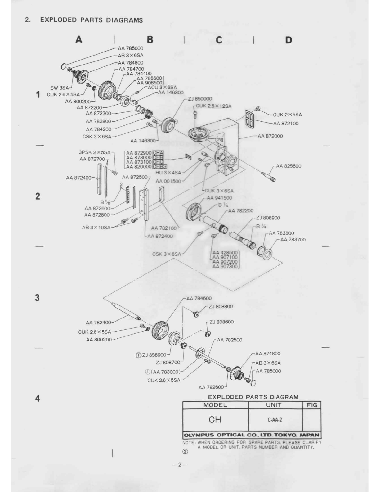
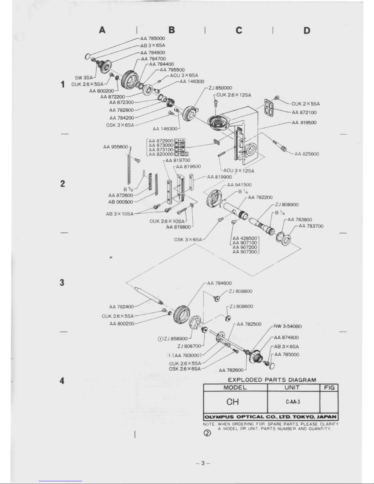
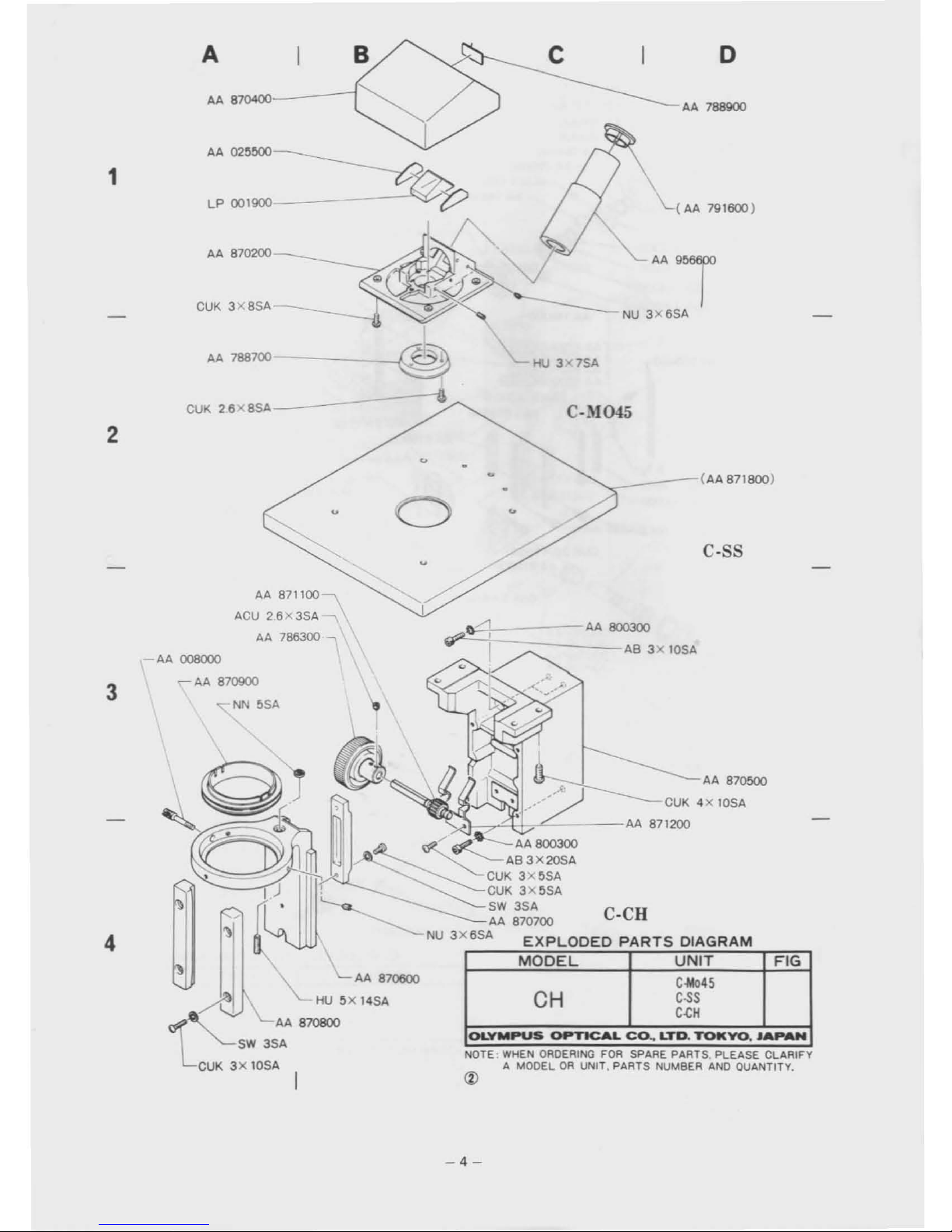
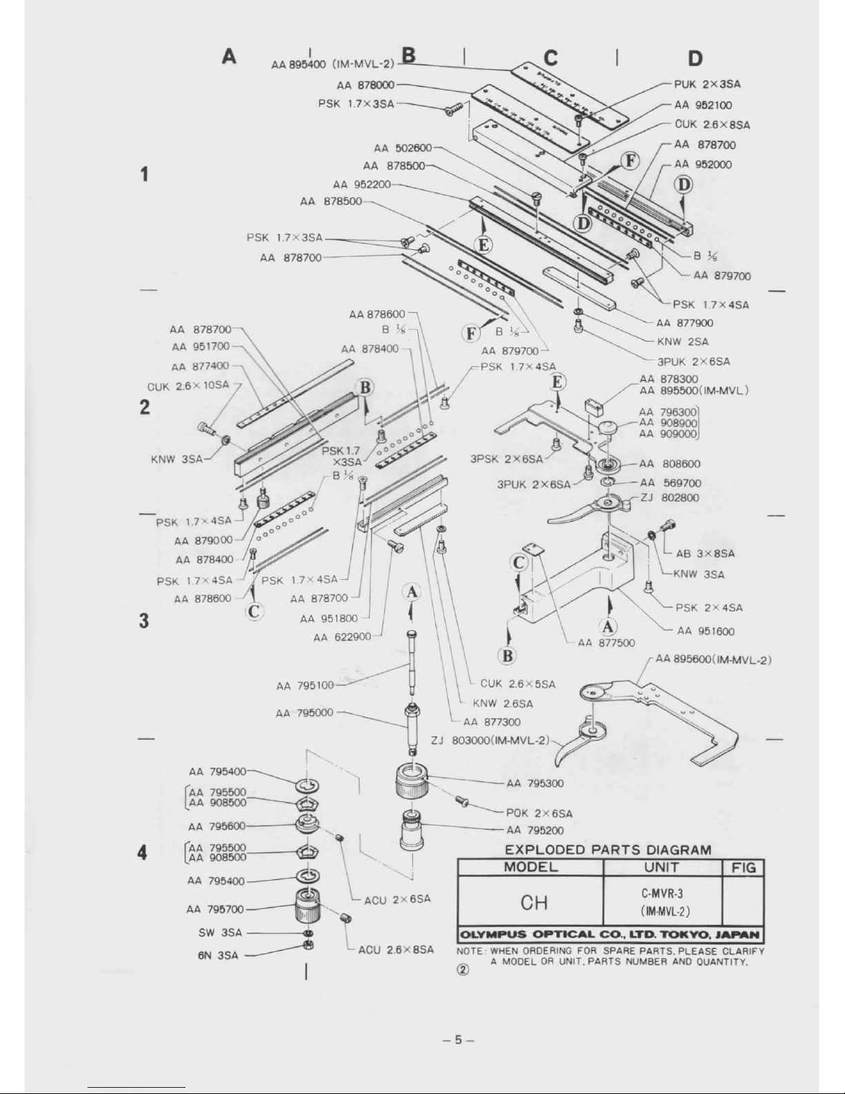
2. EXPLODED PARTS
DIAGRAMS
....................•......•.....•.....
2
3. DISASSEMBLING PROCEDURES FOR CHA·F-3 6
4. REASSEMBLING PROCEDURES FOR CHA·F-3
17
5. DISASSEMBLING PROCEDURES FOR C·CH CONDENSER
HOLDER
31
6. REASSEMBLING PROCEDURES FOR C·CH CONDENSER
HOLDER
34
7. DISASSEMBLING PROCEDURES FOR C-CL
LIGHT
EXiT
37
8. REASSEMBLING PROCEDURES FOR C-CL
LIGHT
EXiT
38
9.
OVERALL
REASSEMBLY
AND
ADJUSTMENT
38
10. DISASSEMBLING
AND
REASSEMBLING PROCEDURES FOR CHA-F
40
11. DISASSEMBLING
AND
REASSEMBLING PROCEDURES FOR C-MVR -45
TO
OLYMPUS
MICROSCOPE
SERVICING
PERSONNEL
CH Series Microscopeiswidely
used
throughout
the
world
for
training
students and inspecting various
specimens. Since
this
microscopeisfrequently
operated
for
routine
microscopy,itistobe
often
repaired
at
your
shop.
Accordingly,
this
manual shouldbehighly
helpful
for
servicing personnel.
As
you
know,
the coarse and fine adjustment mechanismofCH Seriesisnearly the
sameasthatofthe
preceding BH Series.
The
servicing personnel having experience in repairofBH Series
can
therefore easily
repair CH Series.
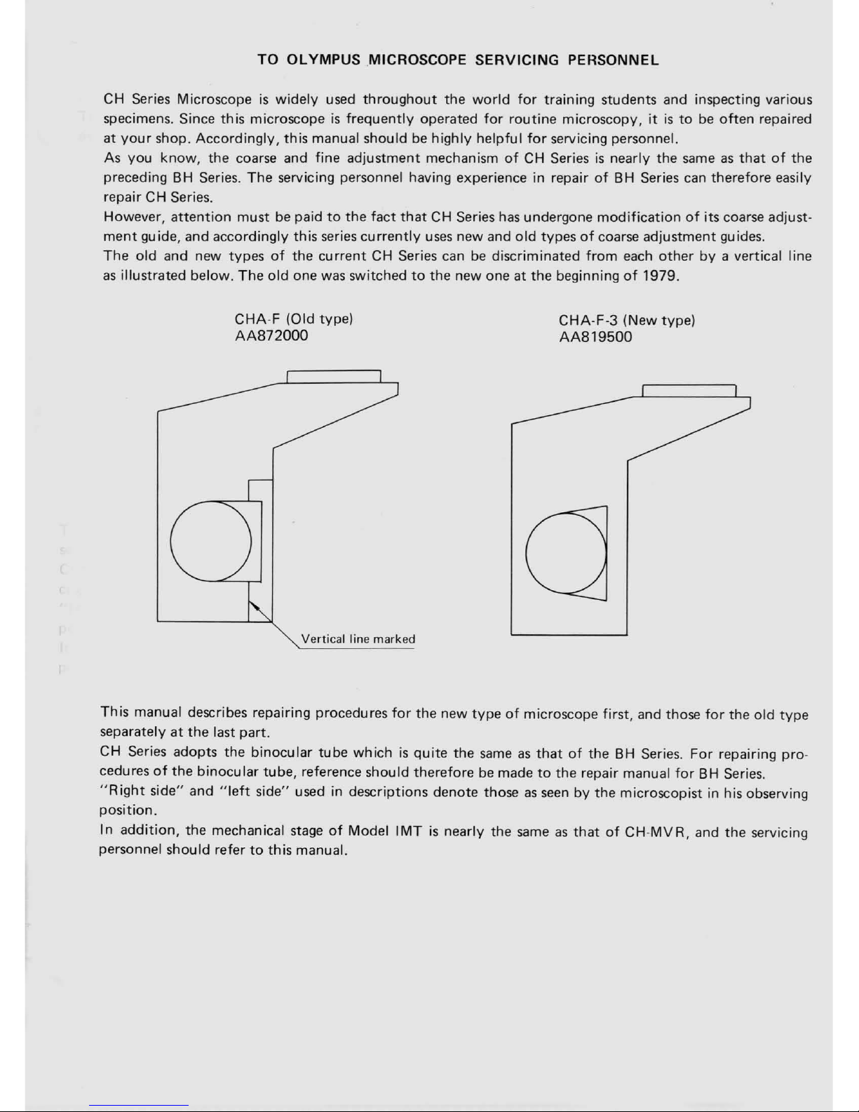
However,
attention
mustbepaidtothe
fact
that
CH Series
has
undergone
modificationofits coarse adjust-
ment
guide, and accordingly
this
series
currently
uses
new and
old
typesofcoarse adjustment guides.
The
old and new typesofthe
current
CH Series can
be
discriminated
from
each
other
by
a vertical line
as
illustrated below.
The
old
one was switchedtothe
new one at
the
beginningof1979.
CHA-F
(Old type)
AA872000
Vertical
line marked
CHA-F-3
(New type)
AA819500
This
manual describes repairing procedures
for
the new
typeofmicroscope
first,
and those
for
the
old
type
separatelyatthe
last part.
CH Series adopts
the
binocular
tube
whichisquite
the
sameasthatofthe BH Series.
For
repairing pro-
cedures
of
the
binocular
tube, reference should thereforebemadetothe
repair manual
for
BH Series.
"R
ight
side" and
"left
side" used in descriptions denote thoseasseenbythe
microscopist in his observing
position.
In
addition,
the mechanical stageofModel
IMTisnearly the
sameasthatofCH-MVR,
and
the
servicing
personnel should refer
to
this
manual.

Requisites
for
repairs:
1. First
of
all, ascertain
what
partsofthe
microscope
the
.userorownerofwhich wishes youtorepair.
2. Never fail
to
check
the
entire
functionofthe
microscope before you commence its repair.
a)
Find
out
what
prts are defective and
how
much
they
are damaged.
b)
Prior
to
repair,
think
of
the
best possible
orderofdisassembling
the
defective partsina most
efficicent way.
3. After completing
the
repair, check
the
functionsofnot
only
the
re-assembled parts
but
also
the
entire
microscope
to
make
sure no
defect
shouldbeleft unremedied.
4.
Be
carefu I
not
to
deform repair
parts
during
the
assembly; make it practicetouse tools and jigs
specified
for
purpose.
5. Make repairs
promptly
and accurately.
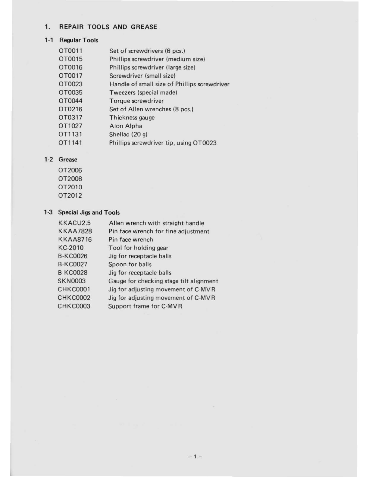
1.
REPAIR
TOOLS
AND
GREASE
1-1
Regular Tools
OTOOll
OT0015
OT0016
OT0017
OT0023
OT0035
OT0044
OT0216
OT0317
OT1027
OTl131
OTl141
1-2 Grease
OT2006
OT2008
OT2010
OT2012
Setofscrewdrivers (6 pes.)
Phillips screwdriver (medium size)
Phillips screwdriver (large size)
Screwdriver (small size)
Handle
of
small sizeofPhillips screwdriver
Tweezers (special made)
Torque
screwdriver
Set
of
Allen
wrenches (8 pes.)
Thickness
gauge
Alon
Alpha
Shellac (20
g)
Phillips screwdriver tiP. using
OT0023
1-3 Special Jigs and Tools
KKACU2.5
Allen
wrench
with
straight handle
KKAA7828
Pin face wrench
for
fine adjustment
K
KAA8716
Pin face wrench
KC-2010
Tool
for
holding
gear
8-KC0026
Jig
for
receptacle balls
8-KC0027
Spoon
for
balls
B-KC0028 Jig
for
receptacle balls
SKN0003
Gauge
for
checking
stage
tilt
alignment
CHKC0001 Jig
for
adjusting movementofC-MVR
CHKC0002
Jig
for
adjusting movementofC-MVR
CHKC0003
Support
frame
for
C-MVR
-1-
2.
PARTS
DIAGRAMS
EXPLODED
CSK 3 6SA
/'
/
~AA825800
o
~
CUK2X5SA
~G
AA 872100
lO
AA 872000
l~~~
AA907200
AA 907300J
--CU
...
3X6SA
A.>
941500
~ .
h(
B.
82200
r
AA
7
ZJ
808900
• -
/B'"
r
AA
783800
AA 783700
ZJ850000
CUK 2.6 x 12SA
i
c
AA
782100"
AA872
3PSK
2X5SA
AA872700
[
AA
8729003000
AA87
AA
873100
AA 820000
• AA 872500
U"'~.~~
AA872800
~
AB3X
10SA
I B
A AA 785000
~
AB3X6SA
AA
784800
84700
Q
AA
~A
7844OO795500J
AA
500
AA~U3X6SA
/
AAI46300
;:~~.!f~/~
AA8002OO2200~~
AA87
AA872300
AA 782800
AA 784200
CSK
3X6SA
2
1
NOTE:MODELORUN
~
AA 7
PARTS
DIA
~
EXPLODED
UNIT
FIG
I
MODEL
C-AA·2
CH
YO
JAPAN
TOk
.
ICAL
CO..LTD.
EASE CLARIFY
OLYMPUS
OPT
FOR SPARE
P~~~SA~~
OUANTITY.
HEN ORDERING
IT
PARTS
filUM
AA 784600
ZJ
808800
~ZJ808600
(;
AA
782500
""""'!l4::
::
82600
GRAM
4
3
-2-
o
NW
3-54080
'AA825600
~~CUK2X5SA
~AA872100
AA 819500
------
c
2J
808600
/"~
AA 782500
2J850000
~CUK
2.B
X 12SA
AA
784600
2J808800
B
•
lACUjX12SA
AA 819900
J
AA941500
,,",~gJ
<
K/"~
:"7~~
AB 000500
~
,~
AA 783700
AB3X10SA
CUK2.BX10SA
/
l:
AA 819800
AA
428500]
AA
907100
CSK 3XBSA
AA
907200
/'
AA907300
/
AA955600
AA
782400
CUK 2.BX5SA
AA800200
~
AA78~
~
AB3X6SA
AA 784800
~
AA
~~4i~400
AA
795500 XBSA
ACU3
/.
AAI46300
O:~;:~~?f
~!~
AA800200
~~
AA872200
AA
872300
"-
AA782800~
~
AA 784200
_______
CSK
3 XBSA
AA14B3OO
[
AA
8729003000.
AA87
AA8=
AA 8 AA 819700
~
AA819600
2
1
3
4
FIG
TICAL
CO.,
LT.
PLEASE
CLARIFY
CH
yo
........
D
TOt(
•
toLYMPUS
OP
G FOR SPARE
PAB~~S
AND
QUANTITY,
QRDERIN
PARTS
NUM
NOTE
WHEN
OR
UNIT
A
MODEL
-3-
OLYMPUS
OPTICAL
Co..
lro.
TOKYO.
JAPAN
NOTE:
WHEN
ORDERING
FDA SPARE PARTS. PLEASE CLARIFY
A MODELORUNIT. PARTS NUMBER
AND
QUANTITY,
FIG
C-Mo45
C-SS
C<:H
C-CR
CH
AA
87ססoo
CUK4X10SA
~~-r'*l/~C-_--
AA
871200
<
fIZ...~AA
800300
____
-z::::--
AS
3X 20SA
CUK
3X5SA
CUK3X5SA
SW
3SA
AA
870700
NU
3X6SA
EXPLODED
PARTS
DIAGRAM
MODEL
UNIT
\.
L
AA
870600
"-
HU5X14SA
AA 870800
SW
3SA
CUK
3X
10SA
4
-4-
o
PUK
2x3SA
NOTE
WHEN
ORDERING FOR SPARE PARTS, PLEASE CLARIFY
<Z)
A MODELORUNIT. PARTS NUMBER
AND
QUANTlTV,
MODEL
UNIT
FIG
CH
C·MVR-3
(IM-MVL-2)
OLYMPUS
OPTICAL
CO.•LTD.
TOKYO.
JA
....
N
ACU
2.6X8SA
I
AA 895400
(IM-MVL
-2)
--'--_--..!..
__
-.<
AA
878000-
---/
PSK
PSK
1.7
X3SA
-~==::::5Il
AA
878700-------,'"
A
AA 878700
AA
951700
AA 877400
CUK 2.6x 10SA
2
3
3PSK 2X
6SA.J
AA
808600
3PUK
2X6SA~
AA
569700
-_.
~ZJ
802600
-PSK
17'
4SA j
000000
;:---
~
~-
~
AA
879000
~oo"
/ I
-d~,).n.
AS
3x8SA
AA
878400
J~~
/~~
PSK
17x4SA
J'i
PSK
17<4SA
II
I
KNW
3SA
AA
878600 C
AA
878700
A(
\ l
.g
r
'-
PSK2X4SA
AA
951800
~
AA
951600
AA
622900
AA
877500
AA 895600(IM-MVL-2)
AA
795100 \ \
K~~\:::5SA~
.•
AA
79!iOOO
~
AA
877300
ZJ
803000(lM-MVL-2) -
f'
AA795400~
~
'1
----
AA
795300
[:
AA
795600
A""
I
AA
908600"'<=l7
I
~
. a POK
2x6SA
AA 795600
~
AA
795200
(AA
795600·.L
l
EXPLODED
PARTS
DIAGRAM
lAA
908600 g I
AA
795400
--®
--J
~
'-ACU
2X6SA
AA
795700~·'
SW
3SA
..
6N
3SA
--------e
I
1
4
-5-

3.
DISASSEMBLING
PROCEDURES FOR CHA-F-3
Fig. 3-1
",--
..
~
C-AA
C-BDA
C-AA:
C-CH:
C-CL:
C-BDA:
Arm
Condenser holder
Light
exit
Electrical
base
plate
Fig. 3-2
Fig. 3-3
AB4x16SA
SW4SA
C-BDA
CUK3x6SA
CUK3x6SA
3- Detaeh Electrical
base
plate C-BDA
from
the
m croscope stand.
3-
-1
Set the microscope stand upside
down
and
en
remove
four
fixing
Screws
AB4x16SA
from
the
base
plate.
(See
Fig. 3-2)
3-'-2
Remove Screw
CUK3x6SA
from
the ground-
,ng line.
(See
Fig. 3-2)
3-1-3
Detaeh
the
electrical
base
platebylihing
it.
3-2
By
removing three Screws
CUK3x6SA,
dis-
mount
Light
exit
C-CL.
(See
Fig. 3-3)
-6-

Fig.34
Fig. 3-5
AA819800
. .
j-
, '
'1'
..
•
..
'
...
Fig. 3-6
3-3 Disassemble Condenser holder C-CH
by
remov·
ing three Screws
AB3xlOSA
and three
Washers
AA800300.
3-3-1 Rack
up
the condenser holder
to
its upper
limit.
Remove Screw
AB3xl0SA
which
is
visible through the notch formed under
Holder
AA870600.
(See
Fig. 3-4)
3-3-2 Rack
down
the condenser holdertoits lower
limit
and then remove
two
Screws
AB3x1OSA.
(See
Fig. 3-5)
3-4 Disassembling procedures
for
coarse adjustment
guide.
NOTE:
For disassembling procedures
of
the coarse
adjustment guide
of
CHA-F (old type),
see
10-1
ofthis
manual.
3-4-1 Detach
two
Fixing pieces
AA819800
by
removing
two
ScrewsCUK2.6x10SA.
(See
Fig. 3-6)
-7-

AA819700
AB3xl0SA
3-4-2 Remove three Screws
AB3x1OSA
from
Inner
gu
ide
AA819700.
(See
Fig. 3-7)
,
-~-
-
.'
-.
-
•.•
. 1 .
J .
~
.,
"
Fig, 3-7
Fig.
3-8
3-4-3 Loosen
two
Screws
AB3x10SA
on Rack
AA819900_
(See
Fig. 3-8)
3-4-4 Disassemble Inner guide
AA819700.
Eight
Bal.s B 5/32 and Casing
AA872600
are
isassembled together
with
the inner guide.
-8-
I
· ,
'-"'"
-,~..
'
,..
,
Fig. 3-9
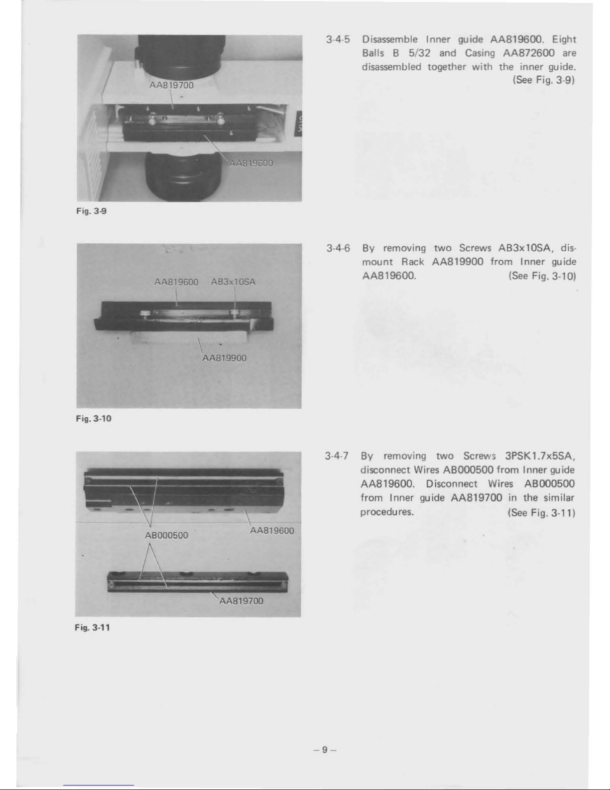
3-4-5 Disassemble Inner guide AA819600. Eight
8alls 8 5/32 and
Casing
AA872600
are
disassembled together
with
the inner guide.
(See
Fig. 3-9)
AA819600
AB3xl0SA
AAB19900
Fig. 3-10
3-4-6
By removing
mount
Rack
AA819600.
two
Screws AB3x10SA. dis·
AA819900
from Inner guide
(See
Fig. 3-10)
3·4-7 By removing
two
Screws 3PSK 1.7x5SA.
disconnect Wires
ABOOO500
from Inner guide
AA819600. Disconnect Wires ABOO0500
from Inner guide
AA819700
in the similar
procedures.
(See
Fig. 3-11)
ABOO0500
AA819600
AA819700
Fig. 3-11
-9-
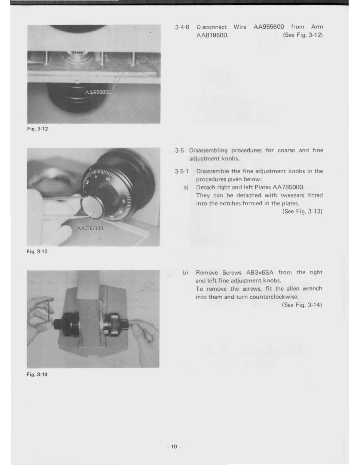
Fig. 3-12
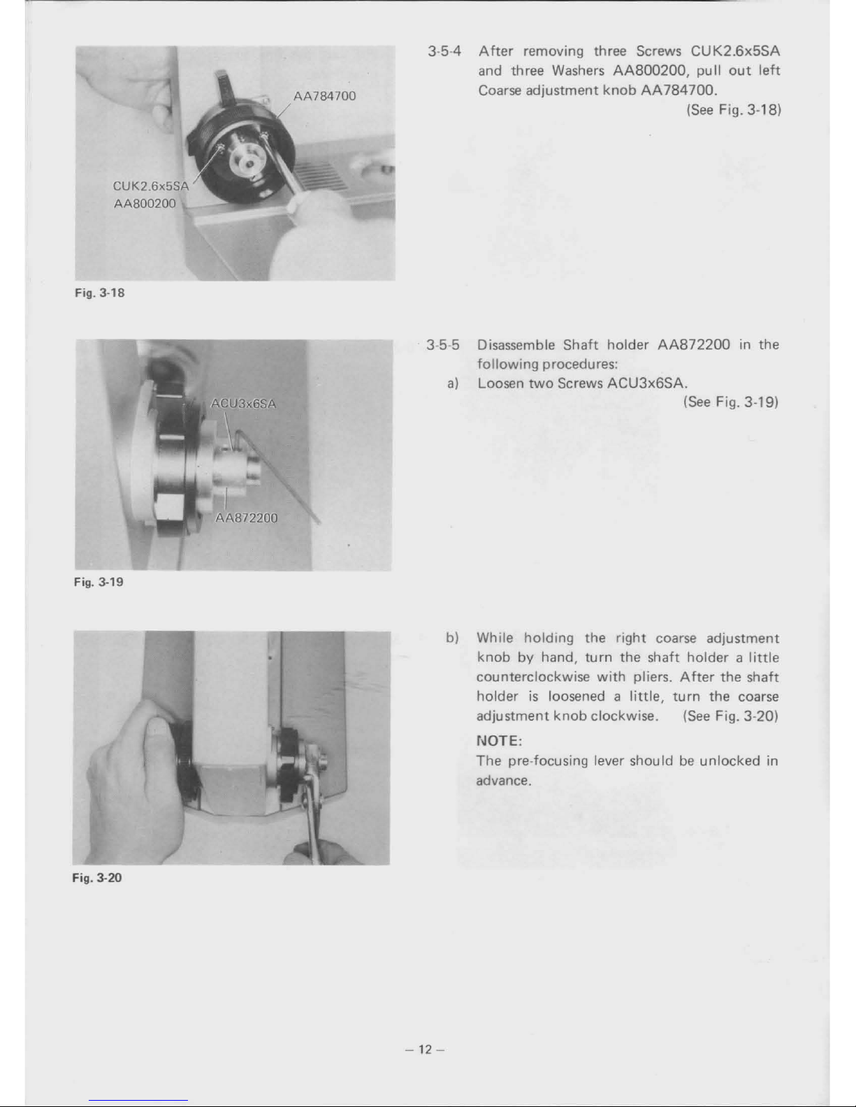
3-4-8 Disconnect Wire
AA955600
from
Arm
AA819500.
(See
Fig. 3-12)
Fig. 3-13
AA785000
3-5 Disassembling procedures
for
coarse and fine
adjustment knobs.
3-5-1 Disassemble
the
fine
adjustment knobs in the
procedures given below:
a)
Detach
right
and
left
PlatesAA785000.
They
can
be
detached
with
tweezers
fitted
into
the
notches
formed
in the plates.
(See
Fig. 3-13)
Fig. 3-14
b) Remove Screws
AB3x6SA
from
the
right
and
left
fine
adjustment knobs.
To
remove
the
screws,
fit
the alien wrench
into
them and
turn
counterclockwise.
(See Fig. 3-14)
-10
-
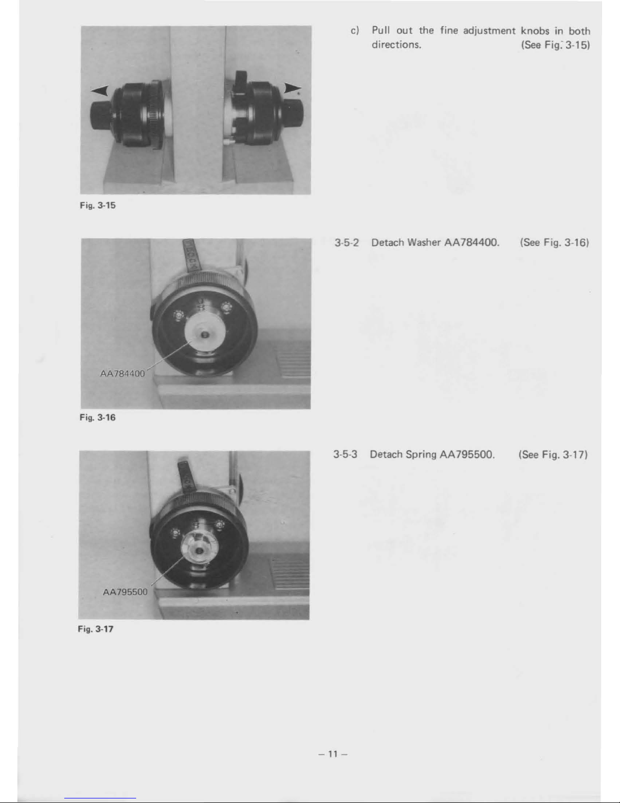
Fig.
3·15
c)
Pull
out
the fine adjustment knobs in both
directions.
(See
Fig:
3-15)
AA784400
Fig.
3·16
3-5-2 Detach
Washer
AA784400.
(See
Fig. 3-16)
Fig.
3·17
3-5-3 Detach Spring AA795500.
-
11
-
(See
Fig. 3-17)
CUK2_6x5SA
AA800200
Fig.
3·18
AA784700
3-5-4
Aher
removing three Screws
CUK2.6x5SA
and three Washers
AA800200,
pull
out
leh
Coarse adjustment
knob
AA784700.
(See
Fig. 3-18)
Fig. 3-19
3-5-5 Disassemble Shaft
holder
AA872200
in the
following
procedures:
a)
Loosen
two
Screws
ACU3x6SA.
(See
Fig. 3-19)
Fig. 3-20
•
b) While
holding
the
right
coarse adjustment
knob
by hand,
turn
the shaft holder a
little
counterclockwise
with
pliers.
After
the shaft
holder
is
loosened a
little,
turn
the coarse
adjustment
knob
clockwise.
(See
Fig. 3-20)
NOTE:
The
pre-focusing lever shouldbeunlocked in
advance.
-12-
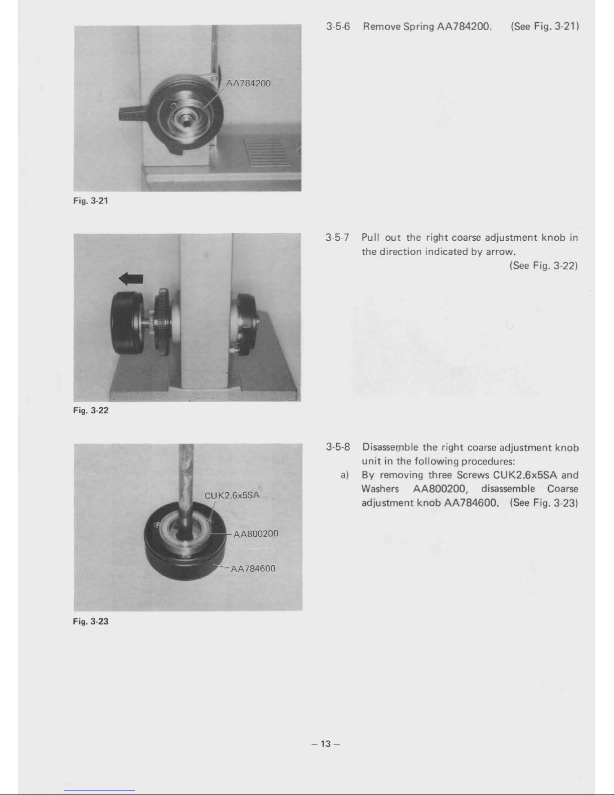
Fig. 3-21
3-5-6 Remove Spring
AA784200.
(See
Fig. 3-21)
Fig. 3-22
AA800200
AA784600
Fig. 3-23
3-5-7
Pullout
the right coarse adjustment
knob
in
the direction indicated
by
arrow.
(See
Fig. 3-22)
3-5-8 Disassel]lble the
right
coarse adjustment
knob
unit
in the
following
procedures:
a)
8y
removing three Screws
CUK2.6x5SA
and
Washers
AA800200,
disassemble Coarse
adjustment
knob
AA784600.
(See
Fig. 3-23)
-13
-
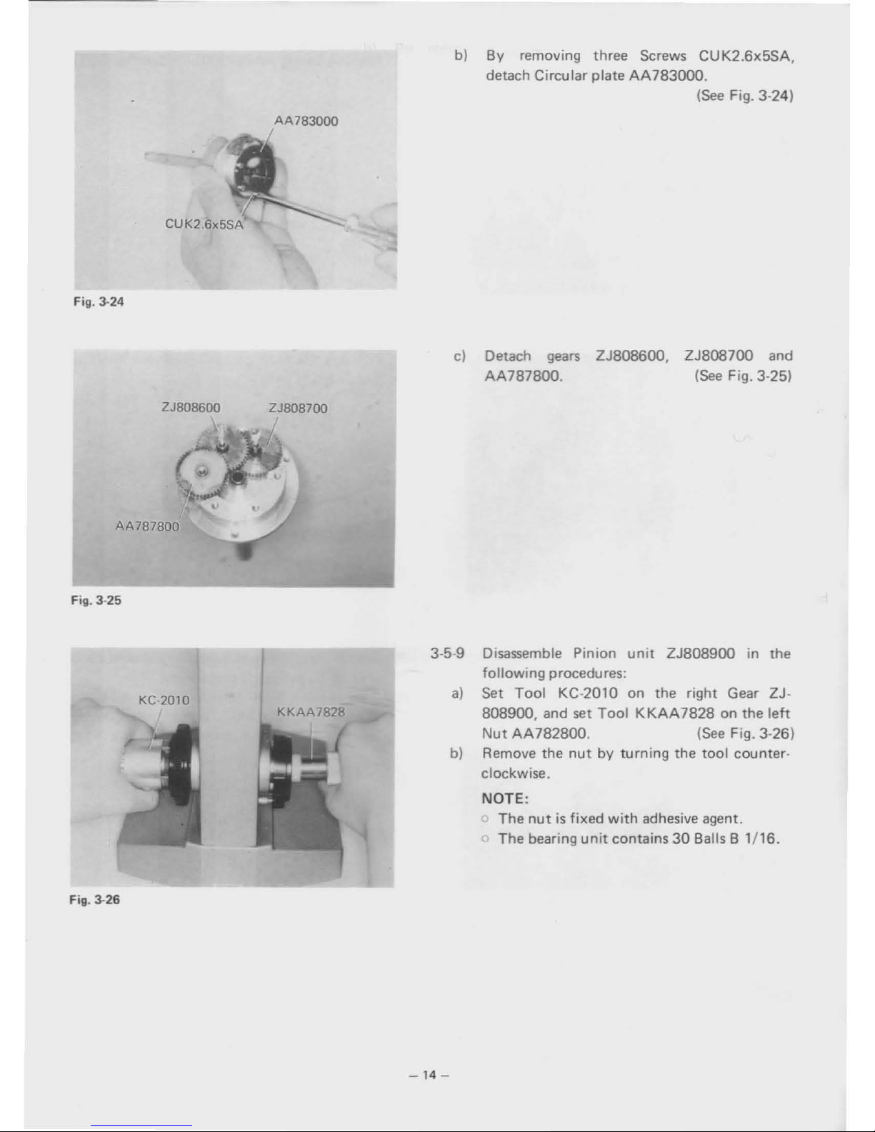
AA783000
Fig. 3-24
b)
By
removing three Screws CUK2.6x5SA,
detach Circular plate
AA783000.
(See
Fig. 3-24)
ZJ808600
AA787800
Fig.
3·25
ZJ808700
c)
Detach
gears
AA787800.
ZJ808600, ZJ808700 and
(See
Fig. 3-25)
KC-2010
Fig.
3·26
3·5-9 Disassemble Pinion
unit
ZJ808900 in the
following procedures:
a)
Set
Tool
KC-2010 on the right Gear ZJ·
808900, and set
Tool
KKAA7828
on the
left
Nut
AA782800.
(See
Fig. 3-26)
b)
Remove the
nut
by
turning the
tool
counter·
clockwise.
NOTE:
The
nutisfixed
with
adhesive agent.
The bearing
unit
contains308alls B
1/16.
-14
-
 Loading...