

Page 1
OLYMPUS STUDENT MICROSCOPES
IINSTRUCTION MANUAL I
MODELS
CBA
&
CBB
Page 2
Scanned
for
personal
by
J.
G.
McHone.8Nov
use
only.
not
for
09
sale
This instruction manual
CHA
and CHB.Itis
yourself
precision instrument.
Observe
•
fully
the
Operation
1.
Always
any
impact.
2.
Avoid
following points carefully.
exposureofthe microscopetodirect
3. Only use
knobs. Do
simultaneously,asthis
recommended
with
your
handle the microscope
the
tension
not
has
been prepared
that
microscope,inordertoobtain
you
for
read
IMPORTANT
with
the careitdeserves. and avoid
twist
adjustment
the
will
ring for altering
two
coarse
cause
damage.
adjustment
the
Olympus
the
manual
sunlight,
Student
carefullyinordertofamiliarize
optimum
dust
and
the
tensionofthe
knobsinthe
Microscopes Models
performance
abrupt
vibration.
coarse
opposite
from
this
motions
or
adjustment
directions
4.
Ascertain
conform
5.
Disconnect the line cord
• Maintenance
1.
Lenses
wiped
prints deposited
xylene, alcoholorether.
2.
Do
especially, should
3.
Never disassemble the microscope
4. The microscope should
possible,itshould be covered
that
the voltage selector switch on the
with
the
local mains voltage.
must alwaysbekept clean. Fine
offbymeansofan
on
not
use
organic solutionstowipe
be
from
the AC power
air
blowerora clean brush.
the lens surfaces
cleaned
with
a neutral detergent.
for
be
stored in its container immediately
with
the
outlet
dust
with
gauze moistened
the surfacesofvarious components. Plastic parts,
repair.
vinyl
dust
base
plateofthe Model
before fuse replacement .
on lens surfaces shouldbeblown
Carefully
cover provided.
wipe
with
after
CHAisset
off
oilorfinger-
a small
amount
use.Ifthisisnot
to
or
of
Page 3
Scanned
for
personal
byJ.G.
use
CONTENTS
McHone.
only.
not
8
Nov
for
09
sale
STANDARD
I.
II.
VARIDUS
ASSEMBLY 4
III.
IV.
IDENTIFICATION
OPERATION .
V.
A.
AdjustmentofMinimum Line Voltage
B.
Placing a Specimen Slideonthe
Interpupillary Distance and Diopter
C.
D.
Tension
E.
Automatic
F.
Aperture
G.
Immersion Objectives
VI.
OPTICAL
EQUIPMENT 2
CDMPONENTS OF
AND
AdjustmentofCoarse
Pre·focusing Lever
Iris Diaphragm 9
DATA.
. .
THE
STUDENT
FUNCTION OF
Stage
Adjustment
MICROSCOPES MODELS
VARIOUS
Adjustments
CDMPONENTS
I<nabs
CHA
& CHB 3
5
7
8
10
VII.
TROUBLESHOOTING.
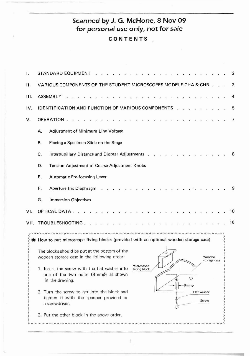
@ How
to
put
The blocks shouldbeput
wooden storage
1.
Insert
the
oneoflhe
in the drawing.
2.
Turn
the screwtogel
tightenitwith
a screwdriver.
3. Put the
other
microscope fixing blocks (provided
at the
bottomofthe
case
in the
following
screw
with
the
flat washer
two
holes (8
the
block in the above order.
mm4>1asshown
into
spanner provided
order:
into
the block and
or
withanoptional
Microscope
fixing
block
wooden
storage case)
<3
--jl-Bmm¢
Flat washer
.____---=.=c.
------
I
Wooden
storage case
"".w
10
Page 4
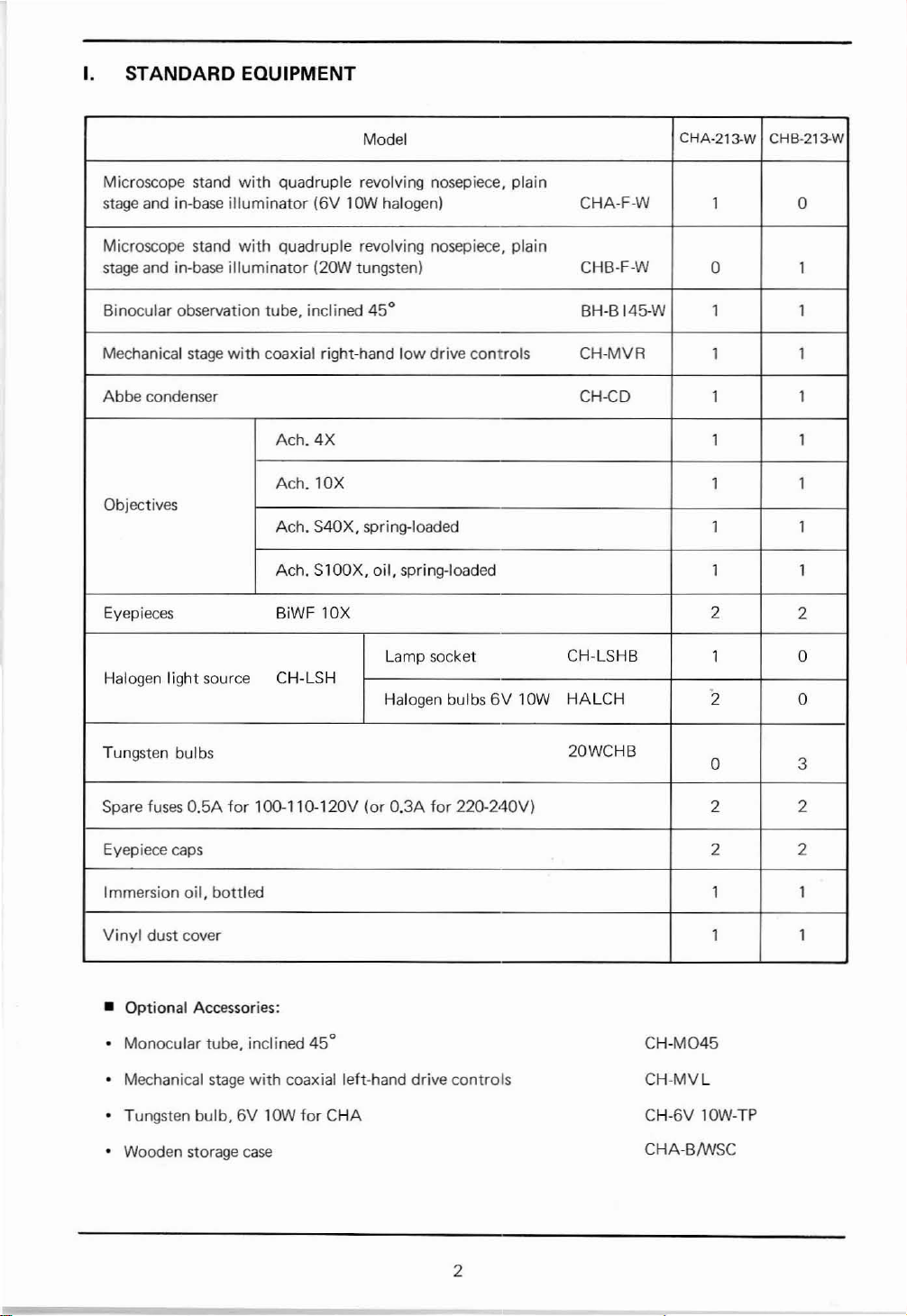
I. STANDARD EQUIPMENT
Microscope
stage
Microscope stand
stage and in-base illuminator
Binocular
Mechanical
Abbe
stand
with quadruple revolving nosepiece, plain
and in-base illuminator
with
quadruple revolving nosepiece, plain
observation
stage
condenser
tube, inclined
with coaxial right-hand
Ach_
Ach_
(6V
(20W
4X
lOX
Objectives
Ach. S40X. spring-loaded 1
Ach. SlOOX,
Eyepieces
BiWF
Halogen light source CH-LSH
Model
lOW halogen)
tungsten)
45°
oil.
lOX
CHA-213-W
low
drive controls CH-MVR
CHA-F-W
CHB-F-W
BH-B
145-W
CH-CD
1 0
0
1 1
1 1
1 1
1 1
1 1
spring-loaded 1 1
2
lOW
CH-LSHB
HALCH
1 0
2 0
Lamp socket
Halogen bulbs
6V
CHB-213-W
1
1
2
Tungsten bulbs
fuses
O.5A
for
Spare
Eyepiece
Immersion oil, bottled 1 1
Vinyl
caps
dust cover 1 1
lOO-110-120V (or O.3A
for
220-240V) 2 2
20WCHB
0 3
2 2
• Optional Accessories:
Monocular tube. inclined
Mechanical stage
with
Tungsten bulb.6VlOW
Wooden storage case
45°
coaxial left-hand drive controls
for
CHA
CH-M045
CH-MVL
CH-6V lOW-
CHA-BIWSC
TP
2
Page 5
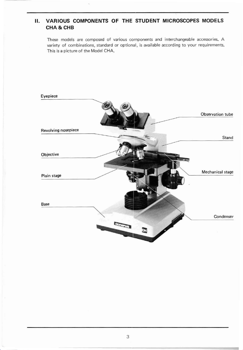
II.
VARIOUS COMPONENTS OF THE STUDENT MICROSCOPES MODELS
CHA&CHB
These models
of
variety
This
Eyepiece
Revolving nosepiece
Objective
Plain stage
combinations, standardoroptional,isavailable accordingtoyour
is
a pictureofthe Model CHA.
are
composedofvarious components and interchangeable accessories. A
requirements.
Observation
Mechanical stage
tube
Stand
Base
Condenser
~
a
3
Page 6

III.
ASSEMBLY
The
the assembly
picture
below
illustrates the sequential procedureofassembly.
orderofvarious components.
The
numbers indicate
* Take care
Securely
stage
to
the
clamping screws and tighten
them
with a coin.
\
@ Mechanical stage
Clamping screws
® Condenser
® Filter
Aligning the
condenser
insert
mount
with
at
assemblytokeep all
attach
the
mechanical II\.
the plain stage
glass
® Eyepiece cap
~'"
with
® Objective
11
---------~g~~g~O~L-®~9~connect
~
1
~
t
mount
the
from
condenser clamping screw.
~
positioning
mount
and condenser,
condenser
below and clamp
dots
into
surfaces clean and avoid scratching the lens surfaces.
(J)
Eyepiece
""">
""-
~
~
Observation
Observation tube
tube
! clamping screw
Stand
th~outlet.
on
the
A Line
~~~
Pull
down
the lamp house cover.
the locking
cord
the plug
knob
to
of
IFor CHB I
I
ForCHA
IFor
CHA
Tungsten bulb
20WCHB
®::J
Halogen Lamp socket
bulb CH-LSHB
I
0--
I
Tungsten
6V10W
Q:::J
Q
bulb
CD
*
* In
* Before use,
4
After
opening the lamp house
cover
at
the microscope base,
press the tungsten bulb socket
against the
rotate
For
useofa halogen
its contact pins into the socket.
caseofthe tungsten
silver reflecting surface must
positioned pointingtothe
plate.
or stains on the resPective bulbs.
lamp
clockwise.
wipe
mount,
bulb,
off
fingerprints
insert
bulb,
and
its
be
base
Page 7

IV.
IDENTIFICATION
AND
FUNCTION OF
VARIOUS
COMPONENTS
Mechanical tube length
adjustment ring
Rotate the
interpupillary
tained
diopter
ringtomatch
distance
from
the
adjustment.
scale. and make
Specimen holder
Low
drive coaxial stage
trois
setting
your
ob-
con~
Interpupillary
distance scale
Observation tube clamping
screw
Loosen the
to
desired.
Graduatedinincrementsof2.5J.L
rotate
clamping
the observation
screw
Tension adjustment ring
Coarse adjustment
Fine
adjustment
slightly
tube
knob
knob
as
•
....
....
<O'!'!
..............
Rheostat trimmer screw
After switching on,ifnecessary.
rotate
this
screw
the
bulbisdimly
sliding
control
voltage position.
Fuse holder
withacoin
switchatminimum
lit,
with
until
the
Main switch
For
continuously
intensitY.
Sliding
control
variable
Grounding
Line voltage selector switch
(For
CHA)
Set
form
with
the
the
local mains voltage.
lever
light
terminal
switchtocon-
5
Page 8

Automatic
pre-focusing lever
Condenser height adjustment
knob
The
condenser is generally used
at
top
objectives
however,itis
lower
eliminate
tion.
position.
the condenser
For
lOX
and
lower
recommended
uneven field
use
power,
properly
illumina-
with
Aperture iris
diaphragm lever
Filter
mount
Slip-in
type
.
..........
to
to
~\~._._~I_~_-,---:::-F~il~te~r-:.mc:07u~n~t
Accepts
45mm
diam.
filters.
Lamp
mount
§iJx~o
6
Lamp house clamping knob
The
lamp
house
cover
openedbypulling
or
closedbypushingitup
snapsinplace.
Before pushing, ascertain
knobispositionedasshown
the
picture
circle.
right,
down
marked
can be
the
until
that
knob;
it
the
in
with
Page 9

V. OPERATION
• SummaryofPutting
1.
Match the line voltage selector switchtolocal mains voltage
page
5,)
2. Switch on
3.
Adjust the
4.
Place
a specimen slide on the
5.
Loosen the
6.
Coarse
focus
7.
Make interpupillary
8.
Swing in the desired objective.
9.
Adjust light intensity.
the Microscope in
the
light source.
trimmer
automatic
withalow
screw.
(See
page
stage.
pre-focusing lever.
power objective.
and
diopter
adjustments.
Operation
7.1
(See
page
7.)
ISee
page
(for
8.)
10. Fine focus.
11. Lock the automatic pre-focusing lever.
12. Adjust the aperture iris diaphragm. ISee
A. AdjustmentofMinimum
The
minimum
trimmer
frequency.
built·in
The
voltage required
screw
at
rheostat incorporates a
Line Voltage (CHA)
the microscope
for
the ligh t source can be adjusted
base
thyristor
(See
page
8.1
page
9.1
plate
in accordance
in its semi-conductor
with
with
the
circuit
advantages:
(a)
Extremely
(bl Flickeringofthe bulb filamentiseliminated and the light intensityisstabilized.
Icl
Increased life expectancyofthe bulb.
For
adjustmentofthe
that
the voltage selector switchissettoconform
the local mains voltage, and the sliding
is
positioned closest
activate the main switch
the secondary
rotate the rheostat
coin,
until
control
intensity. (Fig. 1)
8.
Placing a Specimen Slide on the Stage
NOTE:
fine
adjustmentoflight
minimum
to
you
CD.
VOltageiscorrect.Ifitisnot
trimmer
the
bulbisdimly
lever
forwardinordertoobtain
1) Cover
2) Specimen slide:
glass:
intensity
line
voltage, ascertain
control
(low
voltage). and then
If
the
bulbisdimly
screw @ gradually
lit;
then push the sliding
canbeeasily achieved.
with
lever
CV
lit,
lit
at all,
with
a
optimum
light
Fig. 1
Olympus objectives
use
with
cover
Itisrecommendedtouse
thickness.
However,
for
withanengraving
glassesof0.17mm
specimen slidesofO.8mmto1.5mm
use
with
the immersion
"0.17"
thickness (No. 1%).
darkfield
BH-DCW (optionally availablel. a specimen slide between
O.8mmto1.2mm thicknessispreferable.
CHAI.
line
for
are corrected
(See
the rheostat
voltage and
the
following
condenser
for
7
Page 10

C.
Interpupillary
1)
Hold
left
tubes together,
ever
with
obtained (Fig.
21
Rotate the tube length adjustment ring ®
right eyepiece tube
(
distance setting which
@.
Distance and
the knurled dovetail slides Q)ofthe
eyepiece tubes
or
is
required,
both
while
eyes,
21.
Diopter
with
pull them apart laterally, which-
looking
until
perfect binocular vision
to
you
Adjustments (Binocular tube)
both
hands and push the
through
match
your
obtained
right
the
eyepieces
on
interpupillary
from
the scale
and
is
the
Fig.2
(
3)
Look at the image
your
right eye and focus on the specimen
coarse and
4)
Next,
length adjustment ring
adjustment knobs.
fine
looking
through
adjustment knobs.
at the image through the
@
the
to
focus on
right
eyepiece
with
left
eyepiece
the
specimen
with
the
with
without
your
left
eye
rotate
using the coarse and fine
the tube
D. Tension
A tension adjustment ring
right hand coarse adjustment knob.
tension
either heavyorlight
preference. However,
ment ring
droporthe fine adjustment knobstoslip.
The
*
Be
ment
E.
Automatic
This lever
between specimen and objective
,
coarse focusing. The leverislocked
has
travel
knobs, and automatically provides a
if
automatic
ing. (Fig. 4)
AdjustmentofCoarse
of
the coarse adjustmentisfreely adjustable
movement depending on operator
do
too
much, because this may
arrow
mark indicates increaseofthe tension.
careful
the stage
nottorotate the
knobs in the opposite directions simultaneously.
Pre·focusing Lever
CD
is
providedtoprevent possible contact
been accomplished. This prevents
of
the
stage
by meansofthe coarse adjustment
is
lowered and then raised again. The
pre-focusing lever does
Adjustment
CD
is
provided
not
loosen the tension adjust-
right
and
as
not
Knobs
With
this device the
cause
left
coarse adjust-
wellasto
after
coarse focus
further
limiting
restrict
nexttothe
thE~
fine
for
stage
simplify
upward
stop
focus-
to
Fig. 3
Fig.4
8
Page 11
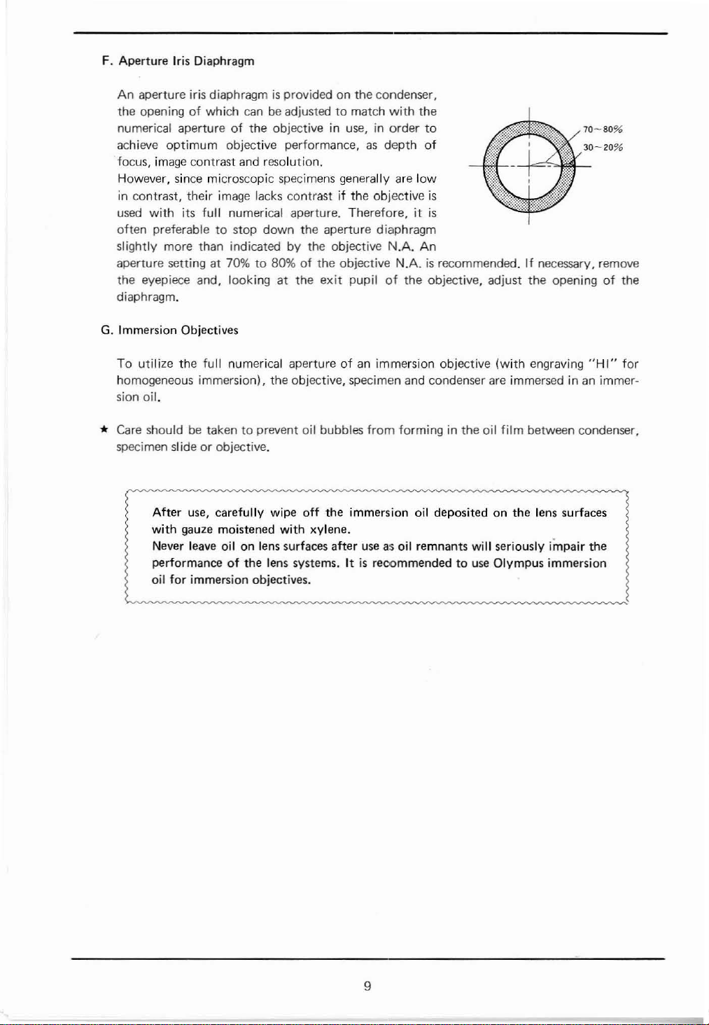
F. Aperture Iris Diaphragm
An
aperture iris diaphragmisprovidedonthe condenser,
the openingofwhich
numerical aperture
achieve
focus, image contrast and resolution.
However, since microscopic specimens generally are
in contrast, their image lacks contrastjfthe objective
used
often
optimum
with
its
preferabletostop
canbeadjustedtomatch
of
the objective in use, in order
objective performance,asdepth
full
numerical aperture. Therefore,itis
down
the aperture diaphragm
with
the
of
low
to
is
70-80%
slightly more than indicated by the objective N.A. An
aperture setting at 70%to80%ofthe objective N.A.isrecommended.Ifnecessary, remove
the eyepiece and, looking at the
exit
pupilofthe objective, adjust
the
openingofthe
diaphragm.
G.
Immersion Objectives
To
utilize
the
full
homogeneous
sion oil.
*
Care
shouldbetakentoprevent oil bubbles
specimen
numerical apertureofan
immersion). the objective, specimen and condenser are immersedinan immer-
sl
ideorobjective.
immersion objective
from
forming
in the oil
(with
engraving
film
between condenser,
"HI"
for
After
use,
carefully wipe
with
gauze moistened
Never
leave
oil on lens surfaces after
performance
for
immersion objectives.
oil
off
with
xylene.
of
the lens systems.Itis
the immersion oil deposited on the lens surfaces
useasoil
recommendedtouse
remnants
will
seriously
Olympus immersion
impair
the
9
Page 12

VI. OPTICAL DATA
Objective
.,
Eyepiece loaded loaded
WFlOX
(Field
number
18)
..
Immersion objective.
*·The
• Working distance: The distance
• Numerical aperture:
• Resolving power:
• Focal
resolving powerisobtainedifthe objectiveisused
diaphragm.
depth:
Type
Magnification
NA
W.D.(mm)
Focal length
Resolving power**{J-L)
Remarks
Total
Focal depth
(mml
magnification
(Il)
4X
0.10
19.87 5.40 0.39 0.11
29.20 15.98 4.31
3.4 1.3 0.52 0.26
40X
172.5 27.60 3.03
Fieldofview (mm) 4.5
from
the specimenorcover glasstothe nearest
of
the objective.
The
N.A.
represents a performance
comparedtothe
of
light
which
the
squareofthe
The
resolving
two
points.
The
distance between
image
formedbyan
relativ(~
the objective receives
performance number.
powerofa lens is measuredbyits
the
optical
Achromat
lOX
S40X
0.25 0.65 1.30
Spring- Spring-
100X 400X 1000X
1.8
with
apertureofa camera lens. The
from
upper
and
lower
system. As
0.45 0.18
the
fully
opened aperture
number
the object- increases
you
which
abilitytoseparate
limitsofsharpness in the
stop
down
the aperture
Sl00X'
1.81
0.66
point
could
quantity
be
with
iris diaphragm, the focal depth becomes deeper. The larger the N.A.
of
the objective the shallower the focal depth.
• Field
•
number:
Field-of-viewdiameter:
A number
field diaphragm
The
that
actual sizeofthe
represents the
thatisformedbythe lensinfrontofit.
fieldofview
diameterinmmofthe imageofthe
in mm.
VII.
TROUBLESHOOTING
Troubles
1. Optical System
a)
Fieldofviewiscut
illuminated
irregularly.
off,
or
Nosepiece
Condenser is
on the ring
Causes
did
not
not
mount.
change
correctly
10
properly.
mounted
Remedies
Slightly
it
Re-insert the condenser all the way.
clicks
rotate
into
the
position.
nosepiece
until
Page 13

Troubles
Causes
Remedies
Dust
bl
dirtisvisible in Dust or
or
the fieldofview. the light
Dustoncondenser top
Dirty
Dust
Excessive
cl
Resolution problems:
dl
·
·
·
image contrast.
I
mageisnot sharp.
Insufficient contrast.
Image
details lack
finition.
Condenser
Aperture iris diaphragm
down excessively.
Objective
ed
Dirtonobjective
de-
Immersion objective
out immersion oil.
Bubbles in the immersion oil.
Olympus immersion oilisnot
Dirty
Dust
top
dirtonthe
exitonthe
specimen.
on
eyepiece.
is
lowered excessively. Raise the condenser.
is
not correctly position- Slightly
in the light path.
front
specimen.
eyepieces and condenser
on
lens.
glass
base.
lens.
lens.
is
surface
is
used
at
Remove dust or dirt.
stopped Open the diaphragm.
rotate the nosepiece until
it
clicks into position.
Clean the objective.
with-
Apply
immersion oil.
Remove bubbles.
used.
Use
Olympus immersion oil.
Clean.
e)
Field of view
of
focus.
out
f)
When objectives are
ed
they are not parfocal.
g)
Light
intensity does
increase although the voltageisraised.
2.
Electric System
a)
Illuminator
(or
too
dark). matched with the mains voltage voltage.
bl
Output
luminator cannot
ulated.
voltage
is
partially Objectiveisnot correctly position-
is
too
for
ed
Specimen
ed
on
chang~
Mechanical tube
rectly adjusted.
Condenserislowered excessively.
not
Rheostat trimmer screw
rectlyadjusted.
bright Voltage
(for
Mains voltage
low).
Rheostat trimmer screw
rectly adjusted.
the
be
Voltage
11-
reg-
matched with the mains voltage voltage.
(for
in the Iight path.
is
not correctly position- Place the specimen on the
the
stage.
selector switch
CHA).
is
selector switch
CHAI.
length
too
Slightly
it
clicks into position.
secureitwith the specimen holder
stage
or
is
not cor-
is
not cor- Adjustitcorrectly.
is
high (or
is
not cor- Adjustitcorrectly.
is
Adjust
ment
ringsonthe observation tube.
Raise
the condenser.
not
Set the switch
too
Adjust
variable voltage transformer.
not
Set the switch to match the mains
rotate the nosepiece until
stage
clips.
with
the
tube
length adjust-
to match the mains
the mains voltage with
and
a
Mains voltageistoo
high).
low
(or too Adjust the
mains voltage with a
variable voltage transformer.
Page 14

c)
Light flickers
tensity
Troubles
is
unstable.
Causes
and
the in· Mains voltageisunstable.
of
Filament
burn out.
Loose
the
electrical connection. Secure the connection.
bulbislikely
Use
a voltage stabilizer.
to
Replace the bulb.
Remedies
dl
Fuse
burns
e)
Bulb does
f)
Reduced bulb life.
out
too
often.
not
light. Bulb
Fuseisnot a standard fuse.
Voltage
matched with the mains voltage. voltage.
Loose
selector switch
is
burned out. Replace the bulb.
electrical connection. Secure the connection.
Voltage selector
matched with the mains \loltage. the mains voltage.
Bulb
is
not a standard one.
Bulb
was
over vol ted too long. Reduce
3. Focusing
a)
Coarse
tight.
b)
Stage drops and the speci- Tension adjustment ring
men
adjustment
goes
outoffocus.
is
Tension adjustment
too
ed
too much. slightly.
Useristrying to
sing
over the upper focusing limit
imposed by the
ing
lever.
loose.
raise
engaged
switch
ring
the
Use
a standard fuse.
is
not
Set the switch to match the mains
is
not
Set the selector switch to match
Use
a standard bulb.
bulb
voltage.
is
tighten- Loosen the tension adjustment ring
stage,
pas-
Unlock the pre-focusing lever.
pre-focus-
is
Tighten the ring slightly.
too
c)
Stage cannot
the upper limit.
dl
Stage
cannot be lowered
to the lower limit
working
Objective front
el
es
the specimen. upside down.
4.
Binocular Observation Tube
Incomplete binocular
al
sion.
range.
be
lens
raised
of
touch-
to
the
Specimen
vi-
rectlyadjusted.
matched.
vision.
Pre-focusing lever
lower than focusing position.
is
Substage
Interpupillary distance
Diopter adjustmentisincomplete. Complete the diopter adjustment.
Right and
User
loweredtomuch.
is
mounted on the
left
is
unaccustomed to binocular Prior to looking at the image of the
engaged
is
eyepieces
not cor-
is
are
in
stage
not
Unlock the pre·focusing lever.
Raise
the
substage.
Reverse the specimen.
Correct the interpupillary distance.
Use
a pairofmatched eyepieces.
try
specimen,
of
field
object before resuming microscopic
observation.
to look at the entire
view, or look at a far away
Page 15

 Loading...