

OLYMPUS C-900 Zoom Adjustment Method V1R2

C. ADJUSTMENT METHOD
C-900ZOOM/D-400ZOOM
C. ADJUSTMENT METHOD
[1] TABLE FOR SERVICING TOOLS .......................................................................... C-2
[2] EQUIPMENT ........................................................................................................... C-2
[3] ADJUSTMENT ITEMS AND ORDER ..................................................................... C-2
[4] SETUP ....................................................................................................................C-2
[5] CONNECTING THE CAMERA TO THE COMPUTER ............................................C-3
[6] ADJUSTMENT SPECIFICATIONS ................................................................ C-4,5,6,7
1. IC501 OSCILLATION FREQUENCY ADJUSTMENT .......................................C-4
2. 5.0 V (A) VOLTAGE ADJUSTMENT..................................................................C-4
3. 3.4 V (D) VOLTAGE ADJUSTMENT.................................................................. C-4
4. 12.4 V (D) VOLTAGE ADJUSTMENT ................................................................ C-4
5. 7.0 V (D) VOLTAGE ADJUSTMENT.................................................................. C-4
6. CCD DEFECT DETECT ADJUSTMENT .......................................................... C-4
7. AWB ADJUSTMENT ...................................................................................... C-4,5
8. COLOR MATRIX ADJUSTMENT ...................................................................... C-5
9. FRANGE-BACK (LENS) ADJUSTMENT..........................................................C-5
10. LCD PANEL ADJUSTMENT ......................................................................... C-5,6
10-1. LCD H AFC ADJUSTMENT ..................................................................... C-6
10-2. LCD RGB OFFSET ADJUSTMENT ......................................................... C-6
10-3. LCD GAIN ADJUSTMENT ....................................................................... C-6
10-4. LCD BLUE BRIGHTNESS ADJUSTMENT .............................................C-6
10-5. LCD RED BRIGHTNESS ADJUSTMENT............................................. C-6,7
10-6. LCD TINT ADJUSTMENT (FOR PAL)......................................................C-7
11. ADJUSTMENT VALUE ....................................................................................C-7
SIEMENS STAR CHART ............................................................................................... C-8
CHECKING OF LENS UNIT .......................................................................................... C-9
SERVER_DIS
C-1
Ver.1/Rev.2
C. ADJUSTMENT METHOD
C-900ZOOM/D-400ZOOM
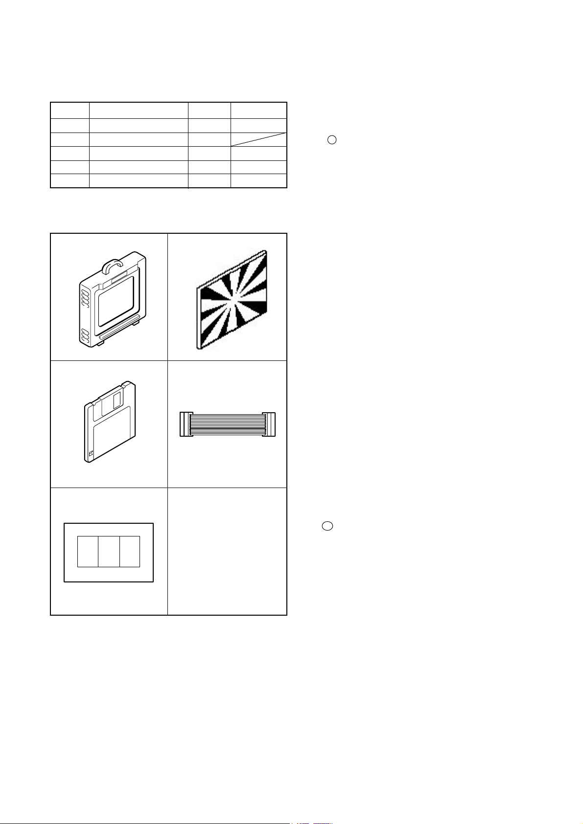
[1] T able for Servicing Tools
Ref. No.
J-1
Color viewer 5,100 K
Siemens star chart
J-2
Calibration software
J-3
Extension cord
J-4
J-5
Chart for color adjustment
Note: J-1 color viewer is 100 - 110 VAC only.
J-4 extension cord is new tool.
Name
Q’ty
1
1
1
1
1
J-1 J-2
J-3
J-4
Part code
VJ8-0007
VJ8-0156
VJ8-0157
VJ8-0155
[2] Equipment
1. Oscilloscope
2. Digital voltmeter
3. AC adaptor
4. IBM R -compatible PC
5. DC regulated power supply
[3] Adjustment Items and Order
1. IC501 Oscillation Frequency Adjustment
2. 5.0 V (D) Voltage Adjustment
3. 3.4 V (D) Voltage Adjustment
4. 12.4 V (L) Voltage Adjustment
5. 7.0 V (L) Voltage Adjustment
6. CCD Defect Detect Adjustment
7. AWB Adjustment
8. Color Matrix Adjustment
9. Flange-back (Lens) Adjustment
10. LCD Panel Adjustment
10-1. LCD H AFC Adjustment
10-2. LCD RGB Offset Adjustment
10-3. LCD Gain Adjustment
10-4. LCD Blue Brightness Adjustment
10-5. LCD Red Brightness Adjustment
10-6. LCD Tint Adjustment (for PAL)
Note:
1. If the lens, CCD, optical filter, board, changing the par t
and disassemble around the lens in item 6-9 replace, it is
necessary to adjust again. “6. CCD Defect Detect Adjustment” can be carried out at any time. Adjustments other
than these should be carried out in sequence.
2. When replacing the lens, first carry out “8. Color Matrix
Adjustment”, and then carry out adjustment steps 6 to 9.
11. Adjustment Values
J-5
[4] Setup
1. System requirements
Windows 95
IBM R -compatible PC with 486 or higher processor
CD-ROM drive
3.5-inch high-density diskette drive
Serial port with standard RS-232C interface
8 MB RAM
Hard disk drive with at least 15 MB available
VGA or SVGA monitor with at least 256-color display
2. Installing calibration software
1. Insert the calibration software installation diskette into
your diskette drive.
2. Open Explorer.
3. Copy the DSC Cal folder on the floppy disk in the FD drive
to a folder on the hard disk.
3. Color Viewer
Turn on the switch and wait for 30 minutes for aging to take
place before using Color Pure.
SER VER_DIS
C-2
Ver.1
C. ADJUSTMENT METHOD
C-900ZOOM/D-400ZOOM
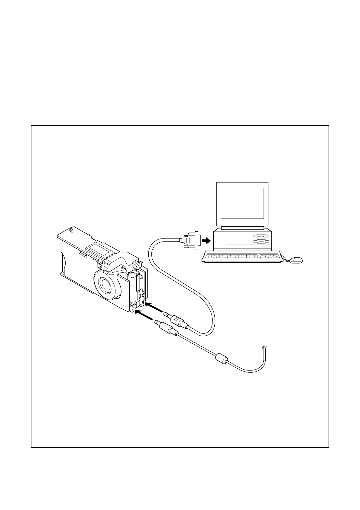
[5] Connecting the camera to the computer
1. Turn off both camera and computer.
2. Locate the port cover on the side of the camera. Press on the arrows and slide the cover down to open it.
3. Line up the arrow on the cable connector with the notch on the camera's serial port. Insert the connector.
4. Locate a serial port on the back of your computer. You may have two serial ports labeled COM1 and COM2, or the ports
may be labeled with icons. If you have two serial ports available, use port 1 to connect your camera.
5. Line up the serial connector on the cable with one of the serial por ts on your computer, and insert the connector.
6. Turn on the camera and your computer system.
To COM1 or COM2 serial port
Serial cable
AC adaptor
SER VER_DIS
C-3
Ver.1
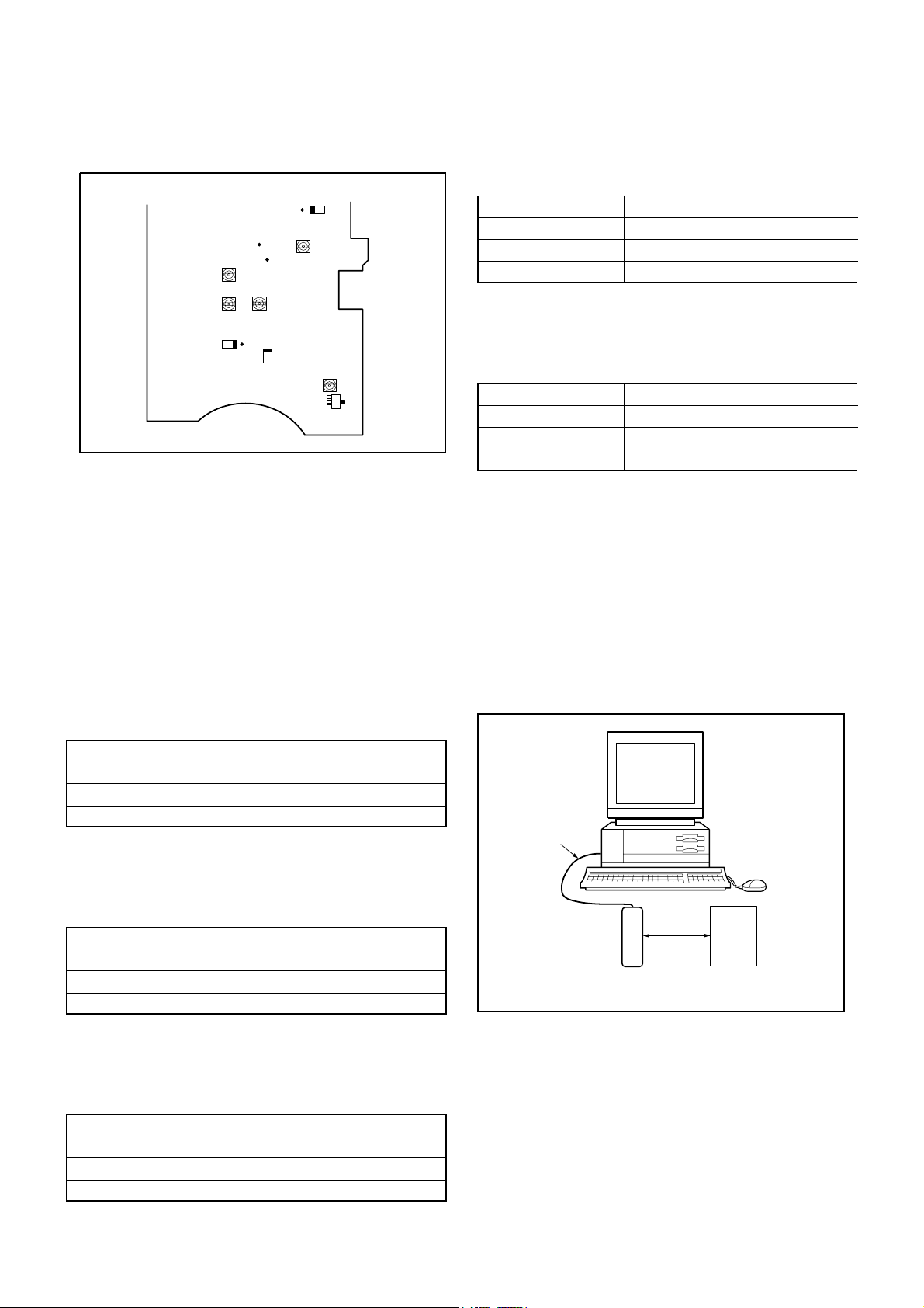
[6] Adjust Specifications
[ST1 board (Side B)]
C. ADJUSTMENT METHOD
Adjustment method:
1. Adjust with VR503 to 3.37 +/- 0.05 V.
4. 12.4 V (L) Voltage Adjustment
C-900ZOOM/D-400ZOOM
CL538
C5053
CL529
C5038
VR501
VR504
VR502
Q5001
Collector
CL531
VR503
VR505
L5012
CL566
Note:
Voltage adjustment is necessary to repair in the ST1 board
and replace the parts.
Preparation:
1. Short Pins 1 and 2 of the S1401 card switch on the ST1
circuit board.
2. Connect the ST1 board and the CA1 board with two
extension cords.
3. Connect LCD panel.
4. Insert the card.
5. Turn on the power switch, and then set the camera mode.
6. Turn on the LCD monitor switch.
1. IC501 Oscillation Frequency Adjustment
Measuring Point
Measuring Equipment
ADJ. Location
ADJ. Value
C5053 or CL538
Digital voltmeter
VR504
12.4 +/- 0.1 V
Adjustment method:
1.Adjust with VR504 to 12.4 +/- 0.1 V.
5. 7.0 V (L) Voltage Adjustment
Measuring Point
Measuring Equipment
ADJ. Location
ADJ. Value
Adjustment method:
1. Adjust with VR505 to 7.00 +/- 0.05 V.
L5012 or CL566
Digital voltmeter
VR505
7.00 +/- 0.05 V
6. CCD Defect Detect Adjustment
Adjustment method:
1. Double-click on the DscCalV120.
2. Select Test “CCD Defect”.
3. Click the Yes, and then the adjustment starts.
4. After the adjustment is completed, OK will display.
5. Click the OK.
7. AWB Adjustment
Measuring Point
Measuring Equipment
ADJ. Location
ADJ. Value
Q5001 Collector
Frequency counter
VR501
200 +/- 1 kHz
Adjustment method:
1. Adjust with VR501 to 200 +/- 1 kHz.
2. 5.0 V (D) Voltage Adjustment
Measuring Point
Measuring Equipment
ADJ. Location
ADJ. Value
Adjustment method:
1. Adjust with VR502 to 5.0 +/- 0.1 V.
C5038 or CL529
Digital voltmeter
VR502
5.0 +/- 0.1 V
3. 3.4 V (D) Voltage Adjustment
Measuring Point
Measuring Equipment
ADJ. Location
ADJ. Value
CL531
Digital voltmeter
VR503
3.37 +/- 0.05 V
Serial cable
Camera
0 - 18 cm
Color viewer
All white pattern
( 5,100K )
Preparation:
POWER switch: ON
Adjusting method:
1. When setting the camera in place, set it to an angle so that
nothing appears in any part of the color viewer except the
white section. (Do not enter any light.)
2. Double-click on the DscCalV120.
3. Click the AWB, and click the Yes.
4. AWB adjustment value will appear on the screen.
(Adjustment value is 249-255 indicates an error.)
SER VER_DIS
C-4
Ver.1
 Loading...