

Page 1

C. ADJUSTMENT METHOD
C-730 Ultra Zoom
C. ADJUSTMENT METHOD
[1] TABLE FOR SERVICING TOOLS .......................................................................... C-2
[2] EQUIPMENT ........................................................................................................... C-2
[3] ADJUSTMENT ITEMS AND ORDER ..................................................................... C-2
[4] SETUP ....................................................................................................................C-2
[5] CONNECTING THE CAMERA TO THE COMPUTER ............................................ C-3
[6] USB STORAGE INFORMATION REGISTRATION ................................................. C-4
[7] ADJUST SPECIFICATIONS ................................................................................... C-4
1. IC501 OSCILLATION FREQUENCY ADJUSTMENT .........................................C-4
2. 5.1 V (A) VOLTAGE ADJUSTMENT ....................................................................C-5
3. LENS ADJUSTMENT .........................................................................................C-5
4. AWB ADJUSTMENT ........................................................................................... C-5
5. CCD WHITE POINT DEFECT DETECT ADJUSTMENT ................................... C-5
6. CCD BLACK POINT DEFECT DETECT ADJUSTMENT IN LIGHTED ............. C-6
7. LCD PANEL ADJUSTMENT ..............................................................................C-6
7-1. LCD H AFC ADJUSTMENT .......................................................................C-6
7-2. LCD RGB OFFSET ADJUSTMENT ........................................................... C-7
7-3. LCD GAIN ADJUSTMENT .........................................................................C-7
7-4. LCD RED BRIGHTNESS ADJUSTMENT................................................. C-7
7-5. LCD BLUE BRIGHTNESS ADJUSTMENT ...............................................C-7
8. EVF ADJUSTMENT ........................................................................................... C-8
8-1. EVF H AFC ADJUSTMENT ........................................................................C-8
8-2. EVF RGB OFFSET ADJUSTMENT ........................................................... C-8
8-3. EVF GAIN ADJUSTMENT .......................................................................... C-8
8-4. EVF RED BRIGHTNESS ADJUSTMENT ................................................. C-9
8-5. EVF BLUE BRIGHTNESS ADJUSTMENT................................................ C-9
[8] ADJUSTMENT ITEMS ..........................................................................................C-10
SIMENS STAR CHART ................................................................................................. C-11
C-1 Ver. 1
Page 2
C. ADJUSTMENT METHOD C-730 Ultra Zoom
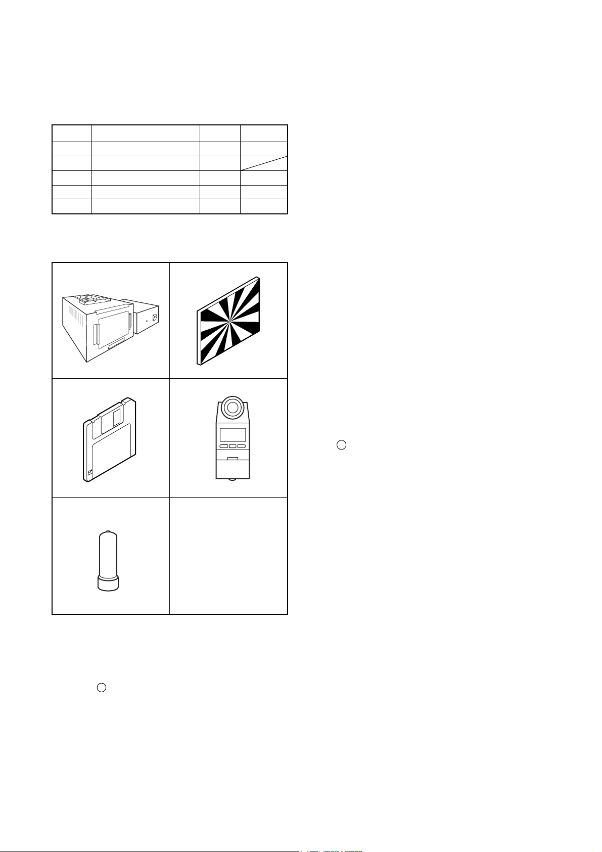
[1] Table for Servicing Tools
Ref. No. Name Part code
J-1
J-2
J-3
J-4
J-5
Note: J-1 color viewer is 100 ± 10 VAC only.
Pattern box (color viewer)
Siemens star chart
Calibration software
Chroma meter
Spare lump
Number
1
1
1
1
1
KC0336
VJ8-0193
KC0337
KC0339
J-1 J-2
J-3
J-4
[3] Adjustment Items and Order
1. IC501 Oscillation Frequency Adjustment
2. 5.1 V (A) Voltage Adjustment
3. Lens Adjustment
4. AWB Adjustment
5. CCD White Point Defect Detect Adjustment
6. CCD Black Point Defect Detect Adjustment in Lighted
7. LCD Panel Adjustment
7-1. LCD H AFC Adjustment
7-2. LCD RGB Offset Adjustment
7-3. LCD Gain Adjustment
7-4. LCD Red Brightness Adjustment
7-5. LCD Blue Brightness Adjustment
8. EVF Adjustment
8-1. EVF H AFC Adjustment
8-2. EVF RGB Offset Adjustment
8-3. EVF Gain Adjustment
8-4. EVF Red Brightness Adjustment
8-5. EVF Blue Brightness Adjustment
Note:
1. If the lens, CCD, board and changing the part in item 36 replace, it is necessary to adjust again. 3-5 adjustments
other than these should be carried out in sequence. Item
6 adjustment should be carried out after item 4.
J-5
[2] Equipment
1. Oscilloscope
2. Digital voltmeter
3. AC adaptor
4. PC (IBM R -compatible PC, Pentium processor, Window
98 or Me or 2000)
[4] Setup
1. System requirements
Windows 98 or Me or 2000 or XP
IBM R -compatible PC with pentium processor
CD-ROM drive
3.5-inch high-density diskette drive
USB port
40 MB RAM
Hard disk drive with at least 15 MB available
VGA or SVGA monitor with at least 256-color display
2. Installing calibration software
1. Insert the calibration software installation diskette into
your diskette drive.
2. Open Explorer.
3. Copy the DscCalDI_129 folder on the floppy disk in the
FD drive to a folder on the hard disk.
3. Installing USB driver
Install the USB driver with camera or connection kit for PC.
4. Pattern box (color viewer)
Turn on the switch and wait for 30 minutes for aging to take
place before using Color Pure. It is used after adjusting the
chroma meter (KC0337) adjust color temperature to 3100
± 20 K and luminosity to 900 ± 20 cd/m
dling the lump and its circumference are high temperature
during use and after power off for a while.
2
. Be careful of han-
C-2 Ver. 1
Page 3
C. ADJUSTMENT METHODC-730 Ultra Zoom
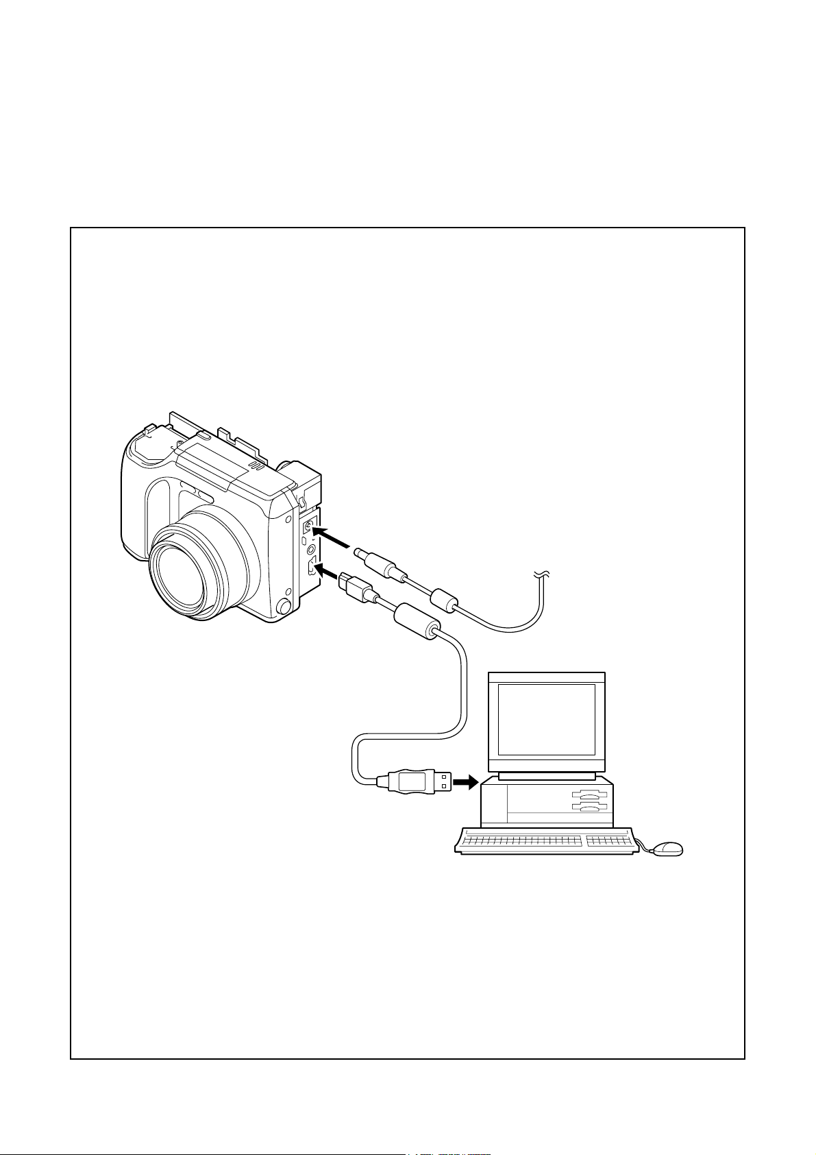
[5] Connecting the camera to the computer
1. Line up the arrow on the cable connector with the notch on the camera's USB port. Insert the connector.
2. Insert the SmartMedia in the camera.
3. Locate a USB port on your computer.
AC adaptor
USB cable
To USB port
C-3 Ver. 1
Page 4
C. ADJUSTMENT METHOD C-730 Ultra Zoom
[6] USB Storage Information Registration
USB storage data is important for when the camera is connected to a computer via a USB connection.
If there are any errors in the USB storage data, or if it has
not been saved, the USB specification conditions will not be
satisfied, so always check and save the USB storage data.
Preparation:
POWER switch: ON
Adjustment method:
1. Connect the camera to a computer. (Refer to [5] Connecting the camera to the computer on the page C-3.)
2. Double-click on the DscCalDi129.
3. Click on the Get button in the USB storage window and
check the USB storage data.
VID: OLYMPUS
PID: C730UZ
Serial:
Rev. : 1.00
4. Check the “Serial” in the above USB storage data. If the
displayed value is different from the serial number printed
on the base of the camera, enter the number on the base
of the camera. Then click the Set button.
5. Next, check VID, PID and Rev. entries in the USB storage data. If any of them are different from the values in
3. above, make the changes and then click the corresponding Set button.
Calibration
AWB
Focus
UV Matrix
Cal Mode
Cal Data
USB storage
VID
Get
PID
Set
OK
OK
Upload
Firmware
Image
Initialize
EVF
LCD Type
LCD
R Bright
RGB Offset
Tint
VCO
H AFC Test
Serial
Set
Set
Rev.
B Bright
Gain
Phase
Set
Set
VCOMDC
VCOMPP
Setting
Language
Video Mode
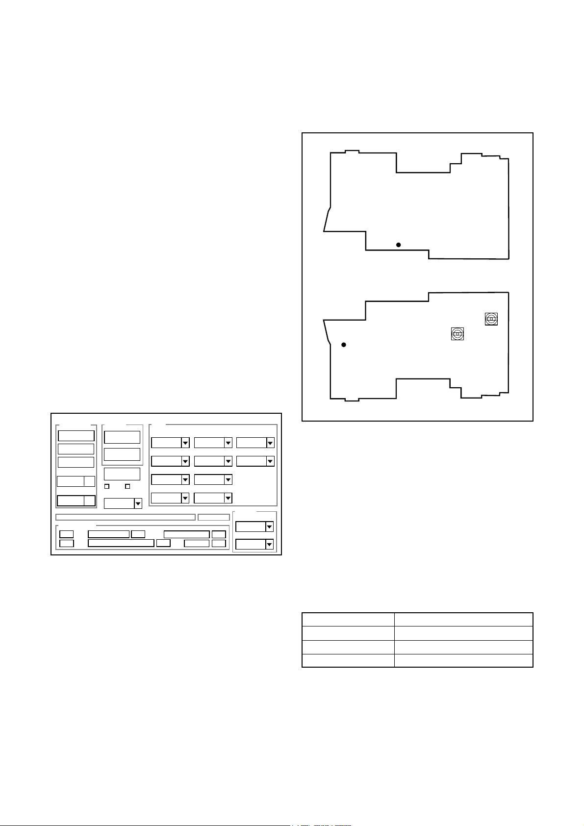
[7] Adjust Specifications
[ST1 board (Side A/B)]
CL552
Side A
VR502
CL528
Side B
Note:
Voltage adjustment is necessary to repair in the ST1 board
and replace the parts.
Preparation:
1. Short Pins 1 and 2 of the S3001 card switch on the CP1
board.
2. Remove the ST1 board from the CP1 board, and solder
the lead wire to CL552 in the ST1 board. Connect ST1
board to CP1 board.
3. Connect the lead wire of EVF backlight.
4. Insert the card.
5. Turn on the power switch, and then set the camera mode.
6. Turn on the LCD monitor switch.
VR501
1. IC501 Oscillation Frequency Adjustment
Measuring Point
Measuring Equipment
ADJ. Location
ADJ. Value
Adjustment method:
1. Adjust with VR502 to 500.1 ± 1 kHz.
C-4 Ver. 1
CL552
Frequency counter
VR502
500.1 ± 1 kHz
Page 5

C. ADJUSTMENT METHODC-730 Ultra Zoom
2. 5.1 V (A) Voltage Adjustment
Measuring Point
Measuring Equipment
ADJ. Location
ADJ. Value
Adjustment method:
1. Adjust with VR501 to 5.10 ± 0.05 V.
CL528
Digital voltmeter
VR501
5.10 ± 0.05 V
3. Lens Adjustment
Camera
Approx.
150 cm ±3 cm
Siemens
star chart
Setting the adjustment mode
1. Open the card cover of the camera.
2. Turn on the power switch.
3. Push the LCD button and OK button more than 3 seconds simultaneously. Display “CAMERA CONTROL OFF
ON”.
4. Push the below arrow button, and select “ON”.
5. Push the OK button.
6. Close the card cover of the camera.
Preparation:
POWER switch: ON
Adjustment condition:
Siemens star chart (A3)
Fluorescent light illumination with no flicker (incandescent
light cannot be used.)
Illumination above the subject should be 400 lux ± 10%.
Adjustment method:
1. Set the siemens star chart 150 cm ± 3 cm so that it becomes center of the screen.
2. Double-click on the DscCalDi129.
3. Click the “Focus”, and Click the “Yes”.
4. Lens adjustment value will appear on the screen.
5. Click the OK.
4. AWB Adjustment
Camera
Pattern box
(color viewer)
Preparation:
POWER switch: ON
Setting of pattern box:
Color temperature: 3100 ± 20 (K)
Luminance: 900 ± 20 (cd/m
2
)
Adjusting method:
1. Set the camera 0 cm from the pattern box. (Do not enter
any light.)
2. Double-click on the DscCalDi129.
3. Click the “AWB”, and click the “Yes”.
4. AWB adjustment value will appear on the screen.
5. Click the OK.
5. CCD White Point Defect Detect Adjustment
Preparation:
POWER switch: ON
Adjustment method:
1. Double-click on the DscCalDi129.
2. Select “CCD Defect” on the LCD “Test”, and click the
“Yes”.
3. After the adjustment is completed, the number of defect
will appear.
C-5 Ver. 1
Page 6

C. ADJUSTMENT METHOD C-730 Ultra Zoom
6. CCD Black Point Defect Detect Adjustment In
Lighted
Camera
Pattern box
(color viewer)
Preparation:
POWER switch: ON
Setting of pattern box:
Color temperature: 3100 ± 20 (K)
Luminance: 900 ± 20 (cd/m
Adjusting method:
1. Set the camera 0 cm from the pattern box. (Do not enter
any light.)
2. Double-click on the DscCalDi129.
3. Select “CCD Black” on the LCD “Test”, and click the “Yes”.
4. After the adjustment is completed, the number of defect
will appear.
2
)
7. LCD Panel Adjustment
[CP1 board (Side B)]
CL410
CL411
CL412
CL414
CL824
CL823
CL822
CL821
CL828
7-1. LCD H AFC Adjustment
Preparation:
POWER switch: ON
Adjusting method:
1. Double-click on the DscCalDi129.
2. Select 0 on the LCD “H AFC”.
3. Apply a trigger using CL828, and adjust LCD “H AFC” so
that the time A from the rising signal at CL828 to the falling signal at CL414 is 5.15 ± 0.1 µsec.
○○○○○○○○
○○
A
CL414
CL828
Enlargement
○○○○○○○○
○○
A
CL414
CL828
C-6 Ver. 1
Page 7

C. ADJUSTMENT METHODC-730 Ultra Zoom
7-2. LCD RGB Offset Adjustment
Adjusting method:
1. Adjust LCD “RGB Offset” so that the amplitude of the
CL410 waveform is 3.95 V ± 0.1 Vp-p.
3.95 V ±
0.1 Vp-p
VG
CL410 waveform
CL410 waveform
7-3. LCD Gain Adjustment
Adjusting method:
1. Adjust LCD “Gain” so that the amplitude of the CL410
waveform is 6.4 V ± 0.2 Vp-p.
Note:
7-2. LCD RGB Offset adjustment should always be carried
out first.
6.4 V ±
0.2 Vp-p
CL410 waveform
7-4. LCD Red Brightness Adjustment
Adjusting method:
1. Adjust LCD “R Bright” so that the amplitude of the CL411
waveform is (VG-0.1) ± 0.1 Vp-p with respect to the CL410
(VG) waveform.
Note:
7-2. LCD RGB Offset adjustment and 7-3. LCD Gain adjustment should always be carried out first.
(VG-0.1) ±
0.1 Vp-p
CL411 waveform
7-5. LCD Blue Brightness Adjustment
Adjusting method:
1. Adjust LCD “B Bright” so that the amplitude of the CL412
waveform is (VG+0.2) ± 0.1 Vp-p with respect to the CL410
(VG) waveform.
Note:
7-2. LCD RGB Offset adjustment and 7-3. LCD Gain adjustment have done.
VG
CL410 waveform
(VG + 0.2)
± 0.1Vp-p
CL412 waveform
C-7 Ver. 1
Page 8

C. ADJUSTMENT METHOD C-730 Ultra Zoom
8. EVF Adjustment
[CP1 board (Side B)]
CL410
CL411
CL412
CL414
CL824
CL823
CL822
CL821
CL828
8-2. EVF RGB Offset Adjustment
Adjusting method:
1. Adjust EVF “RGB Offset” so that the amplitude of the
CL821 waveform is 4.4 V ± 0.1 Vp-p.
4.4 V ±
0.1 Vp-p
CL821 waveform
8-3. EVF Gain Adjustment
Adjusting method:
1. Adjust EVF “Gain” so that the amplitude of theCL821
waveform is 7.2 V ± 0.2 Vp-p.
Note:
8-2. EVF RGB Offset adjustment should always be carried
out first.
8-1. EVF H AFC Adjustment
Preparation:
POWER switch: ON
Adjusting method:
1. Double-click on the DscCalDi129.
2. Click the check box at the “EVF”.
3. Select 0 on the EVF “H AFC”.
4. Apply a trigger using CL828, and adjust EVF “H AFC” so
that the time E from the rising signal at CL828 to the rising signal at CL824 is 2.55 ± 0.1 µsec.
○○○○
○○○○○○○○
E
CL824
CL828
Enlargement
○○○○○
○○○
E
CL824
7.2 V ±
0.2 Vp-p
CL821 waveform
CL828
C-8 Ver. 1
Page 9

C. ADJUSTMENT METHODC-730 Ultra Zoom
8-4. EVF Red Brightness Adjustment
Adjusting method:
1. Adjust EVF “R Bright” so that the amplitude of the CL822
waveform is (VG-0.2) ± 0.1 Vp-p with respect to the CL821
(VG) waveform.
Note:
8-2. EVF RGB Offset adjustment and 8-3. EVF Gain adjustment should always be carried out first.
VG
CL821 waveform
(VG-0.2)
± 0.1 Vp-p
8-5. EVF Blue Brightness Adjustment
Adjusting method:
1. Adjust EVF “B Bright” so that the amplitude of the CL823
waveform is (VG + 0.2) ± 0.1 Vp-p with respect to the
CL821 (VG) waveform.
Note:
8-2. EVF RGB Offset adjustment and 8-3. EVF Gain adjustment have done.
VG
CL821 waveform
(VG + 0.2)
± 0.1 Vp-p
CL822 waveform
CL823 waveform
Completing the adjustment mode
1. Open the card cover of the camera.
2. Turn on the power switch.
3. Push the LCD button and OK button more than 3 seconds simultaneously. Display“CAMERA CONTROL OFF
ON”.
4. Push the above arrow button, and select “OFF”.
5. Push the OK button.
6. Close the card cover of the camera.
C-9 Ver. 1
Page 10

C. ADJUSTMENT METHOD C-730 Ultra Zoom
[8] Adjustment Items
Changed repair parts
Adjustment items
CCD
LENS CA1 ST1
CP1
1.IC501 Oscillation Frequency Adjustment *1○
2. 5.1V(A) Voltage Adjustment *1○
3. Lens Adjustment ○○○ ○
4. AWB Adjustment ○○○ ○
5. CCD White Point Defect Detect Adjustme ○○○ ○
6. CCD Black Point Defect Detect Adjustment
7-1. LCD H AFC Adjustment ○
7-2. LCD RGB Offset Adjustment ○
7-3. LCD Gain Adjustment ○
7-4. LCD Red Brightness Adjustment ○
7-5. LCD Blue Brightness Adjustment ○
8-1. EVF H AFC Adjustment ○
8-2. EVF RGB Offset Adjustment ○
8-3. EVF Gain Adjustment ○
8-4. EVF Red Brightness Adjustment ○
8-5. EVF Blue Brightness Adjustment ○
*1) There is no need that you adjustu the provided ST1 when changing it without changing the parts of
component level.
C-10 Ver. 1
Page 11

C. ADJUSTMENT METHOD C-730 Ultra Zoom
C-11 Ver. 1
 Loading...