

Page 1

C-7070 Wide Zoom
C. ADJUSTMENT METHOD
[1] TABLE FOR SERVICING TOOLS ...........................................................................C-2
[2] EQUIPMENT ............................................................................................................ C-2
[3] ADJUSTMENT ITEMS AND ORDER ...................................................................... C-2
[4] SETUP .....................................................................................................................C-2
[5] CONNECTING THE CAMERA TO THE COMPUTER .............................................C-3
[6] USB STORAGE INFORMATION REGISTRATION .................................................. C-4
[7] ADJUST SPECIFICATIONS .................................................................................... C-5
1. AF LED ANGLE ADJUSTMENT ..........................................................................C-5
2. LENS ADJUSTMENT ..........................................................................................C-6
3. AWB ADJUSTMENT ............................................................................................C-7
4. CCD WHITE POINT DEFECT DETECT ADJUSTMENT ..................................... C-7
5. CCD BLACK AND WHITE POINT DEFECT DETECT
ADJUSTMENT IN LIGHTED .................................................................................C-7
6. PAF ADJUSTMENT .............................................................................................C-8
7. LCD PANEL ADJUSTMENT................................................................................C-9
[8] ADJUSTMENT ITEMS ...........................................................................................C-12
[9] NOTICE AFTER ADJUSTMENT ............................................................................ C-12
SIEMENS STAR CHART.............................................................................................................C-13
C-1 Ver.1
Page 2
C. ADJUSTMENT METHOD C-7070 Wide Zoom
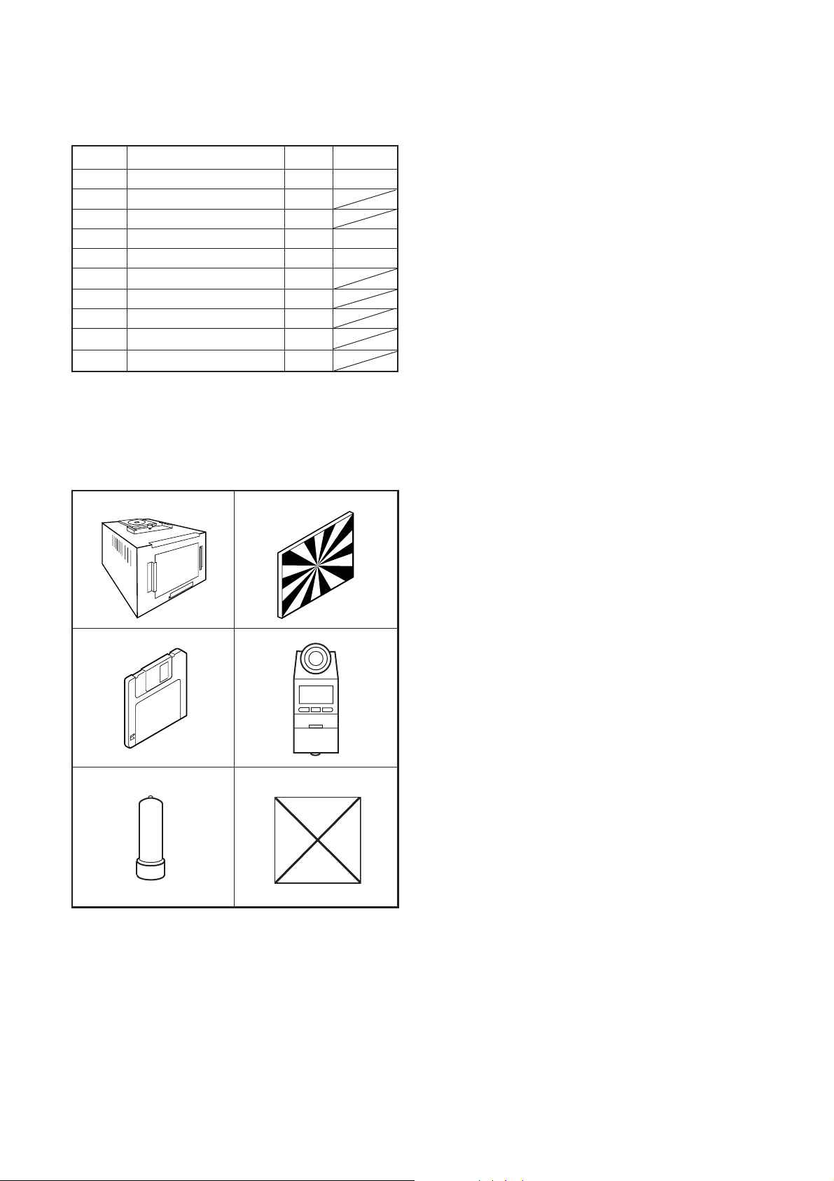
[1] Table for Servicing Tools
Ref. No. Name Part code
J-1
J-2
J-3
J-4
J-5
J-6
J-7
J-8
J-9
J-10
Note: J-1 color viewer is 100 ± 10 VAC only.
Use J-10 collimator made by Kyoritsu Electric Co.
Ltd. or equivalent of it.
Pattern box (color viewer)
Siemens star chart
Calibration software
Chroma meter
Spare lamp
Target board 1
Chart for parallax adjustment
Chart for 0.5 m distance adjustment
Chart for 2.4 m distance adjustment
Collimator 1
J-7 chart for parallax adjustment
Chart creation: Draw a 6 mm thick black line
through the center of an A3 sized paper.
Number
1
1
1
1
1
1
1
1
KC0336
KC0337
KC0339
J-1 J-2
J-3
J-4
[3] Adjustment Items and Order
1. AF LED Angle Adjustment
2. Lens Adjustment
3. AWB Adjustment
4. CCD White Point Defect Detect Adjustment
5. CCD Black Point And White Point Defect Detect Adjustment in Lighted
6. PAF Adjustment
6-1. Uniform Adjustment
6-2. Parallax Adjustment
6-3. Distance Adjustment
7. LCD Panel Adjustment
7-1. LCD H AFC Adjustment
7-2. LCD RGB Offset Adjustment
7-3. LCD Gain Adjustment
7-4. LCD Red Brightness Adjustment
7-5. LCD Blue Brightness Adjustment
7-6. LCD VcomPP Adjustment
Note:
1. If the lens, CCD, board and changing the part in item 2-
5 replace, it is necessary to adjust again.
[4] Setup
1. System requirements
Windows 98SE or ME or 2000 or XP
IBM
® -compatible PC with pentium processor
CD-ROM drive
3.5-inch high-density diskette drive
USB port
40 MB RAM
Hard disk drive with at least 15 MB available
VGA or SVGA monitor with at least 256-color display
J-5 J-6
[2] Equipment
1. Oscilloscope
2. Digital voltmeter
3. AC adaptor
4. PC (IBM
Windows 98SE or ME or 2000 or XP)
® -compatible PC, Pentium processor,
2. Installing calibration software
1. Insert the calibration software installation diskette into
your diskette drive.
2. Open Explorer.
3. Copy the DscCalDI_141 folder on the floppy disk in the
FD drive to a folder on the hard disk.
3. Installing USB driver
Install the USB driver with camera or connection kit for PC.
4. Pattern box (color viewer)
Turn on the switch and wait for 30 minutes for aging to take
place before using Color Pure. It is used after adjusting the
chroma meter (KC0337) adjust color temperature to 3100
± 20 K and luminosity to 900 ± 20 cd/m
dling the lamp and its circumference are high temperature
during use and after power off for a while.
2
. Be careful of han-
C-2 Ver. 1
Page 3
C. ADJUSTMENT METHODC-7070 Wide Zoom
or
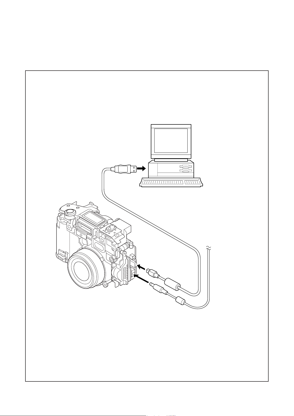
[5] Connecting the camera to the computer
1. Line up the arrow on the cable connector with the notch on the camera's USB port. Insert the connector.
2. Locate a USB port on your computer.
To USB port
USB cable
AC adapt
C-3Ver. 1
Page 4
C. ADJUSTMENT METHOD C-7070 Wide Zoom
[6] USB Storage Information Registration
USB storage data is important for when the camera is connected to a computer via a USB connection.
If there are any errors in the USB storage data, or if it has
not been saved, the USB specification conditions will not be
satisfied, so always check and save the USB storage data.
Preparation:
POWER switch: ON
Adjustment method:
1. Connect the camera to a computer. (Refer to [5] Connecting the camera to the computer on the page C-3.)
2. Double-click on the DscCalDi.exe in the DscCalDi141.
3. Click on the Get button in the USB storage window and
check the USB storage data.
VID: OLYMPUS
PID: C7070WZ
Serial:
Rev. : 1.00
4. Check the "Serial" in the above USB storage data. If the
displayed value is different from the serial number printed
on the base of the camera, enter the number on the base
of the camera. Then click the Set button.
5. Next, check VID, PID and Rev. entries in the USB storage data. If any of them are different from the values in
3. above, make the changes and then click the corresponding Set button.
Calibration
AWB
Focus
UV Matrix
Cal Mode
Cal Data
USB storage
VID
Get
PID
Set
OK
OK
Upload
Firmware
Image
PAF Cal.
EVF
LCD Type
LCD
R Bright
RGB Offset
Tint
VCO
H AFC Test
Serial
Set
Set
Rev.
B Bright
Gain
Phase
Set
Set
VCOMDC
VCOMPP
Setting
Language
Video Mode
Factory Code
C-4 Ver. 1
Page 5

C. ADJUSTMENT METHODC-7070 Wide Zoom
7
y
[7] Adjust Specifications
1. AF LED Angle Adjustment
[CP1 board (Side A)]
CL302
CL301
0 cm
width
of 1cm
black
line
Adjustment condition:
1. This adjustment should be carried out in a fairly dark
place so that the shape of the LED spot can be checked.
2. After adjustment, the readjustment is necessary to replace the lens, CP1 board, CA1 board and the FPC at the
cabinet top.
3. Do not see the light of AF LED directly.
4. Do not adjust long time.
Adjustment method:
1. Set the camera so that the target board is at a distance of
1 meters from LED. (Light up the terget board.)
2. Connect CL301 and CL302. Connect the camera and computer by USB cable. Connect the camera and the TV
monitor by AV cable.
3. Turn on the power, double-click on the DscCalDi.exe.
4. Click the LCD "Test", and select the "Monitor".
Select the "AF LED".
5. Carry out the pre-focus adjustment. After adjusting, the
target mark will appear on the monitor.
6. Turn off the light of target board.
7. Turn the screws on FPC unit to adjust so that the center of the LED spot appears inside the circle above the
target mark on the terget board surface.
8. After adjusting, click the LCD "Test", and select the "LCD
OFF". (The lens will be stowed.)
white
or gra
70 cm
Target board
Target
LED
spot
mark
Setting the adjustment mode
1. Open the card cover of the camera.
2. Turn on the power switch. "CARD-COVER OPEN" will be
displayed in the LCD.
3. Push the LCD button and OK button more than 3 seconds simultaneously.
4. Push the right arrow button, and select "STORAGE".
5. "STORAGE/CONTROL" will be displayed.
6. Push the below arrow button, and select "CONTROL".
7. Push the OK button.
8. Close the card cover of the camera.
C-5Ver. 1
Page 6

C. ADJUSTMENT METHOD C-7070 Wide Zoom
.)
2. Lens Adjustment
Camera
Collimator
(Set up to the infinty
Preparation:
POWER switch: ON
Setup the collimator to the infinity.
Note:
Do not vibrate during the adjustment.
Adjustment method:
1. Set the camera so that it becomes center of the screen in
the collimator.
2. Double-click on the DscCalDi.exe.
3. Click the "Focus",and Click the "Yes".
4. Lens adjustment value will appear on the screen.
5. Click the OK.
Adjustment value determination is effectuated using "FOCUS"
value.
FOCUS=f1, f2, f3, f4, f5 and the adjustment values fulfill the
conditions below, they are determined as within specifications.
Adjustment value determination
Ð156<f1<156, Ð168<f2<168, Ð180<f3<180, Ð190<f4<302,
Ð200<f5<426
3. AWB Adjustment
Camera
Pattern box
(color viewer)
Preparation:
POWER switch: ON
Setting of pattern box:
Color temperature: 3100 ± 20 (K)
Luminance: 900 ± 20 (cd/m
2
)
Adjusting method:
1. Set the camera 0 cm from the pattern box. (Do not enter
any light.)
2. Double-click on the DscCalDi.exe.
3. Click the "AWB", and click the "Yes".
4. AWB adjustment value will appear on the screen.
5. Click the OK.
Adjustment value determination is effectuated using "AGC"
and "CHECK" values.
If AGC=a1, a2, a3, a4, a5, CHECK=wc0, wc1, wc2 and the
adjustment values fulfill the conditions below, they are determined as within specifications.
Adjustment value determination
a1<1023, a2<1023, a3<1023, a4<1023, a5<1023
wc0=128 ± 2, wc1=128 ± 2, wc2=130 ± 40
4. CCD White Point Defect Detect Adjustment
Preparation:
POWER switch: ON
Adjustment method:
1. Double-click on the DscCalDi.exe.
2. Select "CCD Defect" on the LCD "Test", and click the "Yes".
3. After the adjustment is completed, the number of defect
will appear.
(When adjustment is failed, "detect_ng" will display.)
4. Click the OK.
C-6 Ver. 1
Page 7

C. ADJUSTMENT METHODC-7070 Wide Zoom
5. CCD Black Point And White Point Defect Detect
Adjustment In Lighted
Camera
Pattern box
(color viewer)
Preparation:
POWER switch: ON
Setting of pattern box:
Color temperature: 3100 ± 20 (K)
Luminance: 900 ± 20 (cd/m
Adjusting method:
1. Set the camera 0 cm from the pattern box. (Do not enter
any light.)
2. Double-click on the DscCalDi.exe.
3. Select "CCD Black" on the LCD "Test", and click the "Yes".
4. After the adjustment is completed, the number of defect
will appear.
(When adjustment is failed, "detect_ng BLACK x, y" will
display.)
5. Click the OK.
2
)
6. PAF Adjustment
6-1. Uniform Adjustment
Camera
Pattern box
(color viewer)
Preparation:
POWER switch: ON
Setting of pattern box:
Color temperature: 3100 ± 20 (K)
Luminance: 900 ± 20 (cd/m
Note:
Orient the PAF sensor towards the viewer.
Adjusting method:
1. Set the camera 0 cm from the pattern box.
2. Double-click on the DscCalDi.exe.
3. Click the "PAF Cal". "PAF Calibration Dialog" is opened.
4. Click the "Uniformity".
5. Uniformity adjustment value will appear on the screen.
6. Click the OK.
7. This adjustment is to check whether there is a pixel deficiency in the sensor by viewing the graph that appears on
the camera’s LCD. A pixel deficiency or other trouble will
result in fluctuations appearing on the graph.
2
)
C-7Ver. 1
Page 8

C. ADJUSTMENT METHOD C-7070 Wide Zoom
rt
rt
6-2. Parallax Adjustment Adjustment value determination is effectuated using
"PAF_RIGHT_LEFT" value.
LEFT=L1, L2, L3, RIGHT=R1, R2, R3 and the ideal values
and acceptable values fulfill the conditions below, they are
determined as within specifications.
Adjustment value determination
Ideal value of LEFT optic axis difference (L3) = Ð8
Acceptable value of LEFT optic axis difference (L3)
= ideal value ± 10 = Ð18~2
Ideal value of RIGHT optic axis difference (R3) = 14
Acceptable value of RIGHT optic axis difference (R3)
= ideal value ± 10 = 4~24
6-3. Distance Adjustment
Camera
1241.94 mm
±
10 mm
Parallax
adjustment cha
AF frame
Chart for parallax adjustment
Preparation:
POWER switch: ON
Subject: Rotation within ± 10 degrees
Luminance: BV2-6
Temperature: 25 degrees ± 5
Adjusting method:
1. Set the parallax adjustment chart at 1241.94 mm ± 10
mm from CCD.
2. Double-click on the DscCalDi.exe.
3. Click the "PAF Cal". "PAF Calibration Dialog" is opened.
4. Click the "ON" in the PAF Disp. Sensor data graph will be
displayed.
5. Align the AF frame, shown near the center of the LCD
display, with the lateral adjustment chart and set the
camera. (See above figure.)
6. Click the "Parallax".
7. Parallax adjustment value will appear on the screen.
8. Click the OK.
Camera
2.4 m
0.5 m
±
10 mm
±
10 mm
Distance
adjustment cha
Preparation:
POWER switch: ON
Subject: Rotation within ± 10 degrees
Luminance: BV2-6
Temperature: 25 degrees ± 5
Note:
Should adjustment be interrupted before completion, the unit
will start over from the first temperature reading obtained.
Adjusting method:
1. Set the camera turn to the chart.
2. Double-click on the DscCalDi.exe.
3. Click the "PAF Cal". "PAF Calibration Dialog" is opened.
4. Click the "Temp 1". The temperature reading obtained
prior to the distance adjustment is indicated.
5. Enter "0" on the left of "Calibration".
6. Click "Calibration" to initialize.
7. After initializing, adjustment value will be cleared and displayed.
8. Set the chart for 0.5 m distance adjustment at 0.5 m from
PAF.
9. Enter "50" on the left of "Calibration".
10. Click "Calibration".
11. Distance adjustment value will appear on the screen.
C-8 Ver. 1
Page 9

C. ADJUSTMENT METHODC-7070 Wide Zoom
C
12. Set the chart for 2.4 m distance adjustment at 2.4 m
from PAF.
13. Enter "240" on the left of "Calibration".
14. Click "Calibration".
15. Distance adjustment value (0.5 m and 2.4 m) will ap-
pear on the screen.
Adjustment value determination
Determining the adjustment value is done using "TEMP" and
the following 7 lines of values.
Temperature when TEMP = 2-point adjustment (ex. 25.0 →
250)
16-8 = AF adjustment values for each of the 7 blocks for
adjustment between 2 points
1. The temperature difference when adjusting between 2
points should be within ±1 degrees.
2. The adjustment is not OK if the adjustment value for any
one of the 7 blocks is substantially outside the range.
3. The adjustment is not OK if the difference between the
minimum and maximum values is ± 1.0 or more.
4. The adjustment is OK if the camera is moved and then
the difference between the minimum and maximum values is within ± 1.0.
7. LCD Panel Adjustment
[VF1 board (Side B)]
○○○○○○○○
○○
A
CL410
CL416
Enlargement
○○○○○○○○
○○
A
CL410
CL416
7-2. LCD RGB Offset Adjustment
Adjusting method:
1. Adjust LCD "RGB Offset" so that the amplitude of the
CL413 waveform is 0.6 V ± 0.1 Vp-p.
L414(R)
CL410(XENB)
CL412
(B)
CL413(G)
CL411(COM)
CL416
(CSYNC)
7-1. LCD H AFC Adjustment
Preparation:
POWER switch: ON
Adjusting method:
1. Double-click on the DscCalDi.exe.
2. Select 0 on the LCD "H AFC".
3. Apply a trigger using CL416, and adjust LCD "H AFC" so
that the time A from the rising signal at CL416 to the falling signal at CL410 is 3.25 ± 0.1 µsec.
0.6 V ±
0.1 Vp-p
CL413 waveform
7-3. LCD Gain Adjustment
Adjusting method:
1. Adjust LCD "Gain" so that the amplitude of the CL413
waveform is 3.7 V ± 0.15 Vp-p.
Note:
7-2. LCD RGB Offset adjustment should always be carried
out first.
3.7 V ±
0.15 Vp-p
CL413 waveform
C-9Ver. 1
Page 10

C. ADJUSTMENT METHOD C-7070 Wide Zoom
7-4. LCD Red Brightness Adjustment
Adjusting method:
1. Adjust LCD "R Bright" so that the amplitude of the CL414
waveform is (VG+0.05) ± 0.1 Vp-p with respect to the
CL413 (VG) waveform.
Note:
7-2. LCD RGB Offset adjustment and 7-3. LCD Gain adjustment should always be carried out first.
VG
CL413 waveform
7-5. LCD Blue Brightness Adjustment
Adjusting method:
1. Adjust LCD "B Bright" so that the amplitude of the CL412
waveform is VG ± 0.1 Vp-p with respect to the CL413
(VG) waveform.
Note:
7-2. LCD RGB Offset adjustment and 7-3. LCD Gain adjustment have done.
VG
CL413 waveform
CL414 waveform
(VG+0.05)
± 0.1 Vp-p
VG ± 0.1
Vp-p
CL412 waveform
7-6. LCD VcomPP Adjustment
Adjusting method:
1. Adjust LCD "VCOMPP" so that the amplitude of the CL411
waveform is 3.6 V ± 0.1 Vp-p.
3.6 V
± 0.1 Vp-p
CL411 waveform
C-10 Ver. 1
Page 11

C. ADJUSTMENT METHODC-7070 Wide Zoom
Completing the adjustment mode
1. Open the card cover of the camera.
2. Turn on the power switch. "CARD-COVER OPEN" will be
displayed in the LCD.
3. Push the LCD button and OK button more than 3 seconds simultaneously.
4. Push the right arrow button, and select "CONTROL".
5. "STORAGE/CONTROL" will be displayed.
6. Push the below arrow button, and select "STORAGE".
7. Push the OK button.
8. Close the card cover of the camera.
C-11Ver. 1
Page 12

C. ADJUSTMENT METHOD C-7070 Wide Zoom
(
)
[8] Adjustment Items
Adjustment items
1. AF LED Angle Adjustment
2. Lens Adjustment
3. AWB Adjustment
4. CCD White Point Defect Detect Adjustment
5. CCD Black Point Defect Detect Adjustment
in Lighted
6-1. PAF Uniform Adjustment
6-2. PAF Parallax Adjustment
6-3. PAF Distance Adjustment
7-1. LCD H AFC Adjustment
7-2. LCD RGB Offset Adjustment
7-3. LCD Gain Adjustment
7-4. LCD Red Brightness Adjustment
7-5. LCD Blue Brightness Adjustment
7-6. LCD VcomPP Adjustment
Changed repair parts
CA1
CCD
LENS FINDER FPC
CP1
[9] Notice after adjustment
Make sure to reset the camera after adjustment.
Method to reset the camera;
1. Set the camera to the shooting mode and turn power on.
2. Open the card cover (a warning "CARD-COVER OPEN" appears).
3. Press OK button and LCD button simultaneously for about three seconds.
(CAMERA/SDK setup wizard appears.)
4. Choose "RESET" from "CAMERA" and press OK button.
5. Turn the power of the camera off.
C-12 Ver. 1
Page 13

C. ADJUSTMENT METHODC-7070 Wide Zoom
C-13Ver. 1
 Loading...