

Page 1

X-3 / C-60ZOOM
B. DISASSEMBLY AND ASSEMBLY
PROCEDURE
[1] REMOVAL OF FRONT COVER AND BACK COVER............................................. B-2
[2] REMOVAL OF TFT, PW-PCA AND MC-PCA .......................................................... B-3
[3] REMOVAL OF CAM-PCA, VIEWFINDER, PAF-ASSY AND LENS UNIT............... B-4
B-1 Ver.1
Page 2
B. DISASSEMBLY AND ASSEMBLY PROCEDURE X-3 / C-60ZOOM
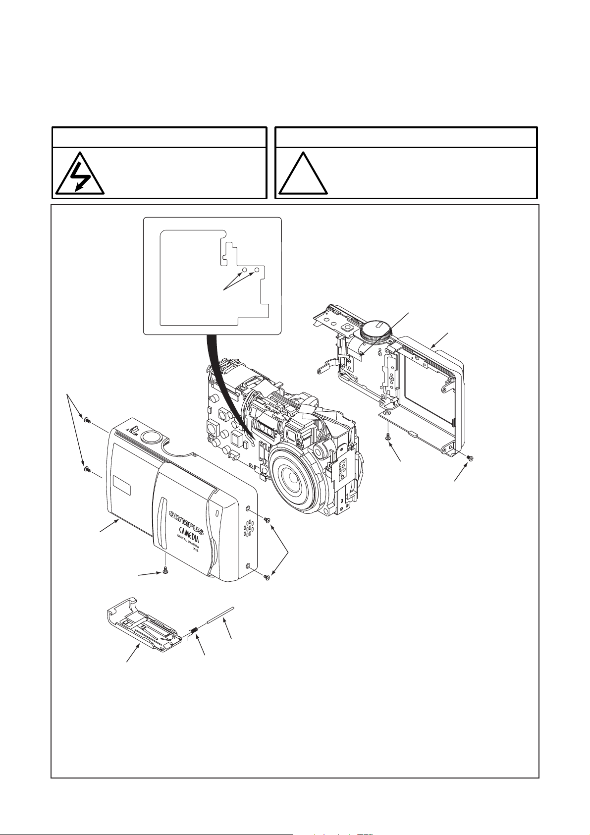
[1] REMOVAL OF FRONT COVER AND BACK COVER
Disassembly perform as follows (1, 2...) and assembly perform by reversing the disassembly steps (...2,1). Be sure to
discharge the main capacitor in procedure 5, then continue to disassembling.
! Beware of electric shock !
Danger of electric shock.
Use a discharging tool to remove
the electrical charge before working.
Discharge
2
Notice
The lead free solder is applied to this product.
!
5
Use the lead free solder in working.
9
8,10
6
7
4
1. Two DecorationScrew1
2. Two DecorationScrew1
3. DecorationScrew2
4. Front cover
(Open jack cover beforehand.)
5. Discharge the main capacitor.
6. DecorationScrew2
7. Screw 1.6x2.5
8. Open back cover slightly.
(Be careful as 9.FPS is connected.)
9. FPC
10. Back cover
11. Battery cover
12. Battery cover shaft
13. Battery cover spring
11
1
3
12
13
B-2 Ver.1
Page 3

B. DISASSEMBLY AND ASSEMBLY PROCEDUREX-3 / C-60ZOOM
[2] REMOVAL OF TFT, PW-PCA AND MC-PCA
26
WHITE
BLUE
GREEN
ORANGE
28
PINK
25
24
23
35
33
32
GREEN
ORANGE
RED
BLACK
32
34
4,8
10
7
29
30
36
37
27
1. Connector
2. SP-Assy
3. Screw 1.6x3.5
4. Separate TFT from adhesive
sponge on the back.
5. Turn SID-FPC the other way.
6. FPC
7. FPC
8. TFT
9. Screw 1.6x3.5
10. TFT-Plate
11. FPC
12. FPC
13. FPC
14. Screw 1.6x6.5
31
13
12
14
19
15. KFAF unit
16. Two screws 1.6x5
17. LensFrame1
18. Screw 1.6x5
19. LensFrame2
20. FPC
21. FPC
22. SID-FPC
23. FPC
24. FPC
25. TOP-FPC
26. Three solders
27. FLReflector-Assy
28. Two solders
29. Screw 1.6x2.5
11
20
21
15
18
9
16
1
5,22
3
17
2
6
30. Three screws 1.6x3.5
31. PW-PCA
32. Four solders
33. Screws 1.6x2.5
34. Two screws 1.6x3.5
35. MC-PCA
36. JackSheet
37. SidePlate
B-3Ver.1
Page 4

B. DISASSEMBLY AND ASSEMBLY PROCEDURE X-3 / C-60ZOOM
[3] REMOVAL OF CAM-PCA, VIEWFINDER, PAF-ASSY AND LENS UNIT
5
6
7
9
8
1
2
3
4
1. Two screws 1.6x4.5
2. CAM-FPC
3. CCD rubber
4. LPF
(Attach IR coated side
towards lens unit.)
5. Screw 1.6x4.5
6. Viewfinder
7. F-Screw
8. PAF-Assy
9. PAF-Spring
A caution in assembling the finder unit
Position protrusion of the finder lens on each cam groove of lens unit.
How to identify IR coated side
As illuminate LPF with fluorescent light, IR coated sur-
face reflects the light pinkly.
Front side is IR
coated surface.
Back side is IR
coated surface.
B-4 Ver.1
 Loading...