

Page 1

X-3 / C-60ZOOM
C. ADJUSTMENT METHOD
[1] TABLE FOR SERVICING TOOLS...................................................................... C-2
[2] EQUIPMENT ...................................................................................................... C-2
[3] SETUP................................................................................................................ C-2
[4] Adjustment items and Order............................................................................ C-3
[5] CONNECTING THE CAMERA TO THE COMPUTER
/ DRIVER INSTALLATION ...........................................................................C-3
[6] ADJUST SPECIFICATIONS............................................................................... C-4
1.Starting of adjustment software................................................................. C-4
2.How to unplug USB cable .......................................................................... C-4
3.Adjustment method .................................................................................... C-5
1)Passive AF1 adjustment......................................................................... C-5
2)ZOOM adjustment ................................................................................... C-6
3)Mechanical shutter adjustment ............................................................. C-6
4)CCD defect adjustment .......................................................................... C-6
5)COLOR adjustment ................................................................................ C-7
6)FOCUS adjustment................................................................................. C-7
7)Passive AF2 adjustment......................................................................... C-8
8)SFR adjustment ...................................................................................... C-9
9)DESTINATION area select...................................................................... C-9
10)Writing of the camera body number.................................................... C-10
11)OPTION.................................................................................................. C -10
C-1 Ver.1
Page 2
C. ADJUSTMENT METHOD
X-3 / C-60ZOOM
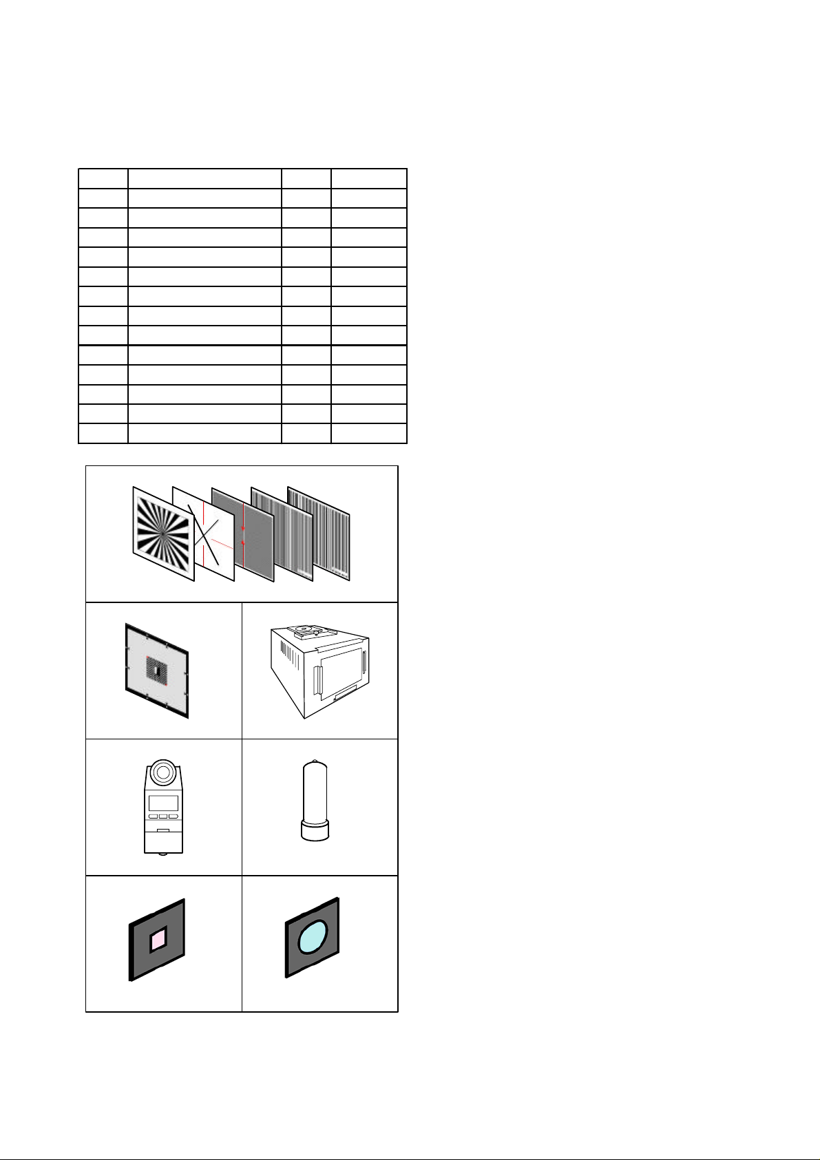
[1] TABLE FOR SEVICING TOOLS
Ref.No. Name Number Part code
J-1 Aset of charts 1
J-2 SFR ch a rt 1 KC0424
J-3 Halogen Viewer 1 KC0336
J-4 Chroma Meter 1 KC0337
J-5 Spare Lamp 1 KC0339
J-6 IR cut filter (with holder) 1 KC0428
J-7 MC filter (with holder) 1 KC0429
Spare IR cu t f il te r 1 KC0426
SpareMC filt e r 1 KC0427
Adjustment software 1
Black cu rta in 1 KC0321
Fluorescent light 1
CEMEDINE High super 5 1 OT 1021
J-1
[2] EQUIPMENT
1. IBM®-compatible PC
2. USB Cable
3. AC adaptor (D-7AC)
4. Thermometer
[3] SETUP
1. System requirements
Windows 98SE/2000
IBM®-compatible PC with Pentium processor
CD-ROM drive
3.5-inch high-density diskette drive
USB port
8 MB RAM
Hard disk drive with at least 15 MB available
VGA or SVGA monitor with at least 256-color display
2. Installing adjustment software
1) Install the set up file in an optical folder.
2) Open “ Explorer “ and double-click
“ OL_Calib194_Ver*.*_SETUP.EXE ” file.
3) Start Install Wizard.
4) After installation, " C:\Di\OL Calib194 " directory will
be created.
J-2 J-3
J-4 J-5
J-6
J-7
C-2 Ver.1
Page 3
[4] Adjustment Items and Order
-
C. ADJUSTMENT METHODX-3 / C-60ZOOM
Adjustment i te ms
1)Passive AF1 adjustment---------
2)ZOOMadjus tment------------------[2.ZOOM]
3)Mechanical shu tter adjustment-[3.Mecha Shutter]
4)CCD defect adjustment-----------[4.CCD Defect]
5)Color adjustment------------------- [5.Color Matrix]
6) F ocus adjust ment------------------ [6.Focus]
7)Passive AF2 adjustment----------[7.PAF2]
8)SFR adjutmsnt-----------------------[8.SFR]
9)Destin a ti on ar ea select -----------[9.Destination]
10)Writing of the camera Body number
[1.PAF1]
Lens Unit CCD-ASSY LPF MC-PCA2
O
OOOO
OOOO
OOOO
OOOO
OOOO
OOOO
OOOO
Changed parts
O
O
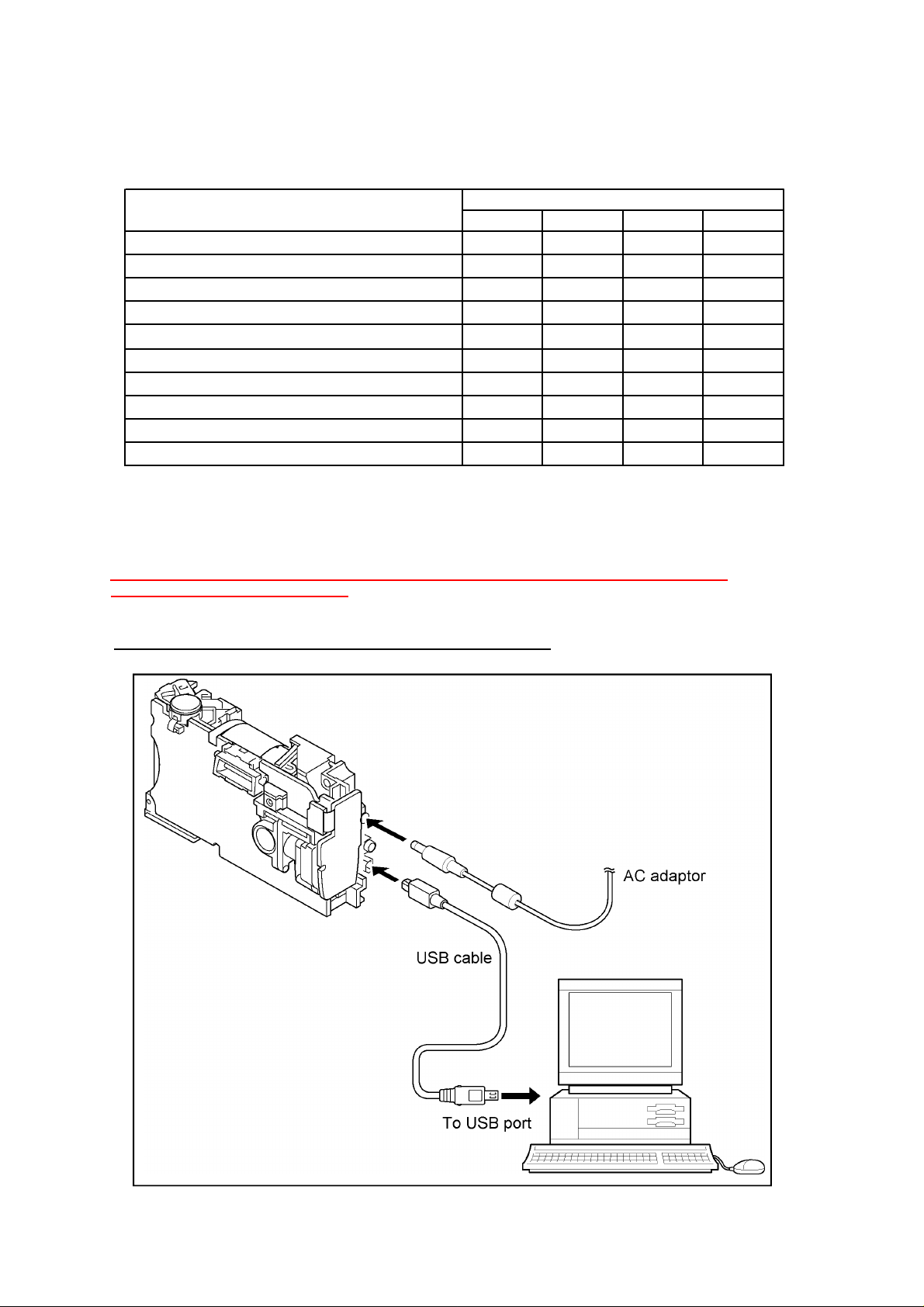
[5] CONNEC TING TH E CAMER A TO TH E COMPUTER / DRIVER INSTALLATION
1. Insert an AC adapter and a USB cable in the camera.
Note) A personal computer sometimes stops when a power supply is plugged in and out with
a USB cable inserted in the camera.
2.Choose "PC" from LCD monitor and push [OK] button.
3. If recognized as new hardware, install a driver.
Location to save the driver : C: \ Di \ OL_Calib194 \ USB Port Driver
Fig.3-1
C-3Ver.1
Page 4

C. ADJUSTMENT METHOD
[6] ADJUSTMENT SPECIFICATIONS
1. Launch the adjustment software
1) Double-click "C:\Di\OL_Calib194\OL_Calib194_Ver*.*.exe"
2) At the initial launch, two windows open first.
(the window behind doesn't show on Windows 98)
3) Select the language used on PC and the number of "USB Mass storage device"
shown on the window. Click [OK]. (Fig.4-1)
(select only the language on Windows 98)
4) Confirmation message appears and click [Yes]. (Fig.4-2)
5) Adjustment program starts up and a menu screen appears. (Fig.4-.3)
X-3 / C-60ZOOM
Fig.4-1 Fig.4-2
Fig.4-3
2.
How to unplug USB cable
Outline:
On the version other than Windows 98, a warning message appears if unplug USB cable without preparation.
Add a new command in order to unplug USB cable safely and easily.
Operation procedure:
(1) Click [USB Unplug]. (Fig.4-3)
(2) Confirm "TRUE" indication. (Fig.4-4)
(3) Unplug USB cable.
Fig.4-4
C-4 Ver.1
Page 5

C. ADJUSTMENT METHODX-3 / C-60ZOOM
3.Adujustment method
1) Passive AF1 adjustment
Preparation:
(1) Put the camera body in a state where exterior parts are
not assembled yet.
(2) Set xD card.
(3) Assemble back cover and card cover with the body first
and fasten with decoration screw 2 (VE568100). (Fig.5-1)
(4) Connect FPCB of the back cover with the connector.
(5) Keep some space between front cover and back cover
as F-screw (VE397100) can be seen.
(6) Connect AC adapter and USB cable. Press [OK] button
on the back cover to shift to PC mode.
(7) Open the barrier.
Procedure:
(1) Click [1.PAF-1] (Fig.5-2)
(2) The camera starts set-up.
(3) Align lens end face and chart at a distance of 60cm+/-0.5cm.
(Fig.5-3)
(4) Align cross hairs of the LCD on red lines of the chart.
(Fig.5-4)
(5) Click [Start]. (Fig.5-5)
(6) AF sensor graph appears (black lines of the chart are shown
in the form of the mountain). (Fig.5-6)
(7) Turn F-screw round and adjust a angle of AF module so that
the graph becomes one big mountain.
(8) Click [Exit] after making adjustment.
(9) Confirm “True” indication and take USB cable off.
(Fig.5-7)
(10) Fix F-screw with adhesive (High super 5) and assemble
external parts.
(11) Adjustment completes.
60cm +/-0.5cm
Camera
PAF1 Chart
Fig.5-3
Fig.5-4
Fig.5-5
F-Screw
Decoration Screw 2
Fig.5-1
Fig.5-2
PAF ASSY
BAD
GOOD
BAD
Fig.5-6
Fig.5-7
C-5Ver.1
Page 6

C. ADJUSTMENT METHOD
2) Zoom adjustment
Preparation:
-Camera is in communication with PC
-Open the barrier.
Procedure:
(1) Click [2.ZOOM] (Fig.6-1)
(2) Adjustment starts.
(3) Confirm “True” indication appears. (Fig.6-2)
(4) Adjustment completes.
3) Mechanical shutter adjustment
Preparation:
-Camera is in communication with PC
-Open the barrier
-Halogen viewer spec brightness : 900+/-100(lux)
color temperature : 3100+/-100(K)
Procedure:
(1) Click [3.M.Shutter] (Fig.6-1)
(2) The camera starts set-up.
(3) Set the camera at 0 to 5cm distance from Halogen
Viewer so that it becomes center of the screen. (Fig.6-3)
(4) Cover a camera with black curtain.
(5) Click [Start]. (Fig.6-4)
(6) Adjustment starts.
(7) Confirm “True” indication appears. (Fig.6-2)
(8) Adjustment completes.
X-3 / C-60ZOOM
Fig.6-1
Fig.6-2
0 - 5cm
Camera
Halogen Viewer
Fig.6-3
4) CCD defect adjustment
Preparation:
-Camera is in communication with PC
-Open the barrier
-The camera unit shouldn’t be heated.
-Halogen viewer spec brightness : 900+/-100(lux)
color temperature : 3100+/-100(K)
-Set a MC filter on Halogen Viewer. (Fig.6-5)
Procedure:
(1) Click [4.CCD Defect] (Fig.6-1)
(2) The camera starts set-up.
(3) Set the camera at 0 to 5cm distance from Halogen
Viewer so that it becomes center of the screen. (Fig.6- 5 )
(4) Cover a camera with black curtain.
(5) input the circumference temperature of the camera and
click [OK]. (Fig.6-6)
(6) Adjustment starts.
(7) Confirm “True” indication appears. (Fig.6-2)
(8) Adjustment completes.
Fig.6-4
MC filter
0 - 5cm
Camera
Halogen Viewer
Fig.6-5
Fig.6-6
C-6 Ver.1
Page 7

C. ADJUSTMENT METHODX-3 / C-60ZOOM
5) COLOR adjustment
Preparation:
-Camera is in communication with PC
-Open the barrier
-Halogen viewer spec brightness : 900+/-100(lux)
color temperature : 3100+/-100(K)
-Take a filter off from Halogen Viewer
Procedure:
(1) Click [5.Color Matrix] (Fig.7-1)
(2) The camera starts set-up.
(3) Set the camera at 0 to 5cm distance from Halogen
Viewer so that it becomes center of the screen. (Fig.7- 2 )
(4) Cover a camera with black curtain.
(5) Click [Start]. (Fig.7-3)
(6) Adjustment starts.
(7) Set a IR cut filter on Halogen Viewer. (Fig.7-2 )
(8) Cover a camera with black curtain.
(9) Click [Start]. (Fig.7-4)
(10) Adjustment starts.
(11) Confirm “True” indication appears. (Fig.7-5)
(12) Adjustment completes.
IR cut filter
0 - 5cm
Camera
Halogen Viewer
Fig.7-2
Fig.7-3
Fig.7-1
6) FOCUS adjustment
Preparation:
- Camera is in communication with PC
- Open the barrier
- Siemens star chart (A3) (Fig.7-6)
- Illuminate the chart by a fluorescent light with no flicker
(incandescent light cannot be used)
(Brightness should be 400lux+/-10% on the chart face)
Procedure:
(1) Click [6.Focus] (Fig.7-1)
(2) The camera starts set-up.
(3) Set the camera at 60cm +/-0.5cm distance from Halogen
Viewer so that it becomes center of the screen. (Fig.7-7)
(5) Click [Start]. (Fig.7-8)
(6) Adjustment starts.
(3) Confirm “True” indication appears. (Fig.7-5)
(4) Adjustment completes.
Fig.7-4
Fig.7-5
60 +/-0.5cm
Camera
Siemens star chart
Fig.7-6
Fig.7-7
Fig.7-8
C-7Ver.1
Page 8

C. ADJUSTMENT METHOD
7) Passive AF2 adjustment
Preparation:
- Camera is in communication with PC
- Open the barrier
- Illuminate the chart by a fluorescent light with no flicker
(Brightness should be 400lux+/-10% on the chart face)
- The camera unit shouldn’t be heated.
Procedure:
(1) Click [7.PAF-2]. (Fig.8-1)
(2) Set up the camera.
(3) Align lens end face and chart at a distance of
30cm+/-0.5cm. (Fig.8-2)
(4) Align the vertical line of LCD on the arrow of chart 1.
(Fig.8-3)
(5) Click [Start]. (Fig.8-4)
(6) Adjustment starts.
(7) Align lens end face and chart 2 at a distance of
30cm+/-0.5cm. (Fig.8-2)
(8) Look into the finder and align the center of the finder
to the center of chart 2.
(9) Click [Start]. (Fig.8-5)
(10) Adjustment starts.
(11) Align lens end face and chart 3 at a distance of
120cm+/-1cm. (Fig.8-2)
(12) Look into the finder and align the center of the finder
to the center of chart 3.
(13) Click [Start]. (Fig.8-6)
(14) Adjustment starts.
(15) Align lens end face and chart 2 at a distance of
30cm+/-0.5cm again. (Fig.8-7)
(16) Look into the finder and align the center of the finder
to the center of chart 2. (Fig.8-2)
(17) Click [Start]. (Fig.8-7)
(18) AF check starts.
(19) Confirm “True” indication appears. (Fig.8-8)
(20) Adjustment completes.
X-3 / C-60ZOOM
Fig.8-3
Fig.8-4
Fig.8-5
Fig.8-6
Camera
30 +/-0.5cm
PAF2-2 chart
Fig.8-7
Fig.8-1
Fig.8-8
PAF2-1 chart
120 +/-1cm
PAF2-3 chart
Fig.8-2
C-8 Ver.1
Page 9

C. ADJUSTMENT METHODX-3 / C-60ZOOM
8) SFR adjustment
Preparation:
- Camera is in communication with PC
- Open the barrier
- Illuminate the chart by a fluorescent light with no flicker
(Brightness should be 400lux+/-10% on the chart face)
Procedure:
(1) Click [8.SFR]. (Fig.9-1)
(2) Set up the camera.
(3) Place the camera in the position where triangular
marks of SFR chart on top and bottom, left and
right come adjacent to four sides of the field view
(distance is about 135cm). (Fig.9-2,3)
(4) Click [Start]. (Fig.9-4)
(5) Adjustment starts.
(6) Confirm “True” indication appears. (Fig.9-5)
(7) Adjustment completes.
135 +/-10cm
Camera
SFR chart
Fig.9-2
Fig.9-1
9) Destination area select
Preparation:
- Camera is in communication with PC
Procedure:
(1) Click [9.Destination] (Fig.9-1)
(2) Select destination area. (Fig.9-6)
(3) Click [Write]
(4) Writing starts.
(6) Confirm “True” indication appears. (Fig.9-5)
(7) Adjustment completes.
Fig.9-3
Fig.9-4
Fig.9-5
Fig.9-6
C-9Ver.1
Page 10

C. ADJUSTMENT METHOD
10) Writing of the camera body number
Preparation:
- The camera is in communication with PC
Procedure:
(1) Open the option menu. (Fig.10-1)
(2) Enter a body number and click [Write]. (Fig.10-1-(1))
(3) Confirmation message appears and click [Yes].
(4) Writing starts.
(5) Confirm “True” indication.
(6) Setting completes.
X-3 / C-60ZOOM
(2)
(3)
(6) (7)
11) OPTION
Function:
(2) Get Versions
(Contents)
- Firmware version
- Serial number of Main C.B.A
- Body number
- Pass flag of adjustment
(3) Search Device
“ TRUE ” : Device dection
“ FALSE ” : Undevice detection
(4) USB OPEN
“ TRUE ” : USB is connected
“ FALSE ” : USB communication error
(5) USB CLOSE
USB communication OFF
(8)
(4)
(5)
Fig.10-1
(6) Data Save
- Data of a camera is saved.
save folder : “ C: \ Di \ OL_Calib194 \ Data Save \ ...BodyNo.csv ”
(7) Data Load
- Save data is loaded.
Note: After loading data, adjust “ Mechanical shutter ”
(8) Switch Check
- Click [Check Start]
- The check signal is displayed on each check box when pressing
- Press [ESC] key when finishing “ Switch check “
(9) Damage Code
- Damage history is displayed.
Note: Check the history with this function before adjust so
(1)
(9)
each switch of camera.
that the history is erase after adjustment.
C-10 Ver.1
 Loading...