

Page 1

X-450/D-535ZOOM/C-370ZOOM
B. DISASSEMBLY AND ASSEMBLY
PROCEDURE
[1] REMOVAL OF FRONT / BACK COVER AND BODY .............................................. B-2
[2] REMOVAL OF MAIN PCB, FLASH PCB AND LENS UNIT .................................... B-3
[3] DISASSEMBLY OF CCD UNIT ................................................................................B-4
B-1 Ver.1
Page 2
B. DISASSEMBLY AND ASSEMBLY PROCEDURE X-450/D-535ZOOM/C-370ZOOM
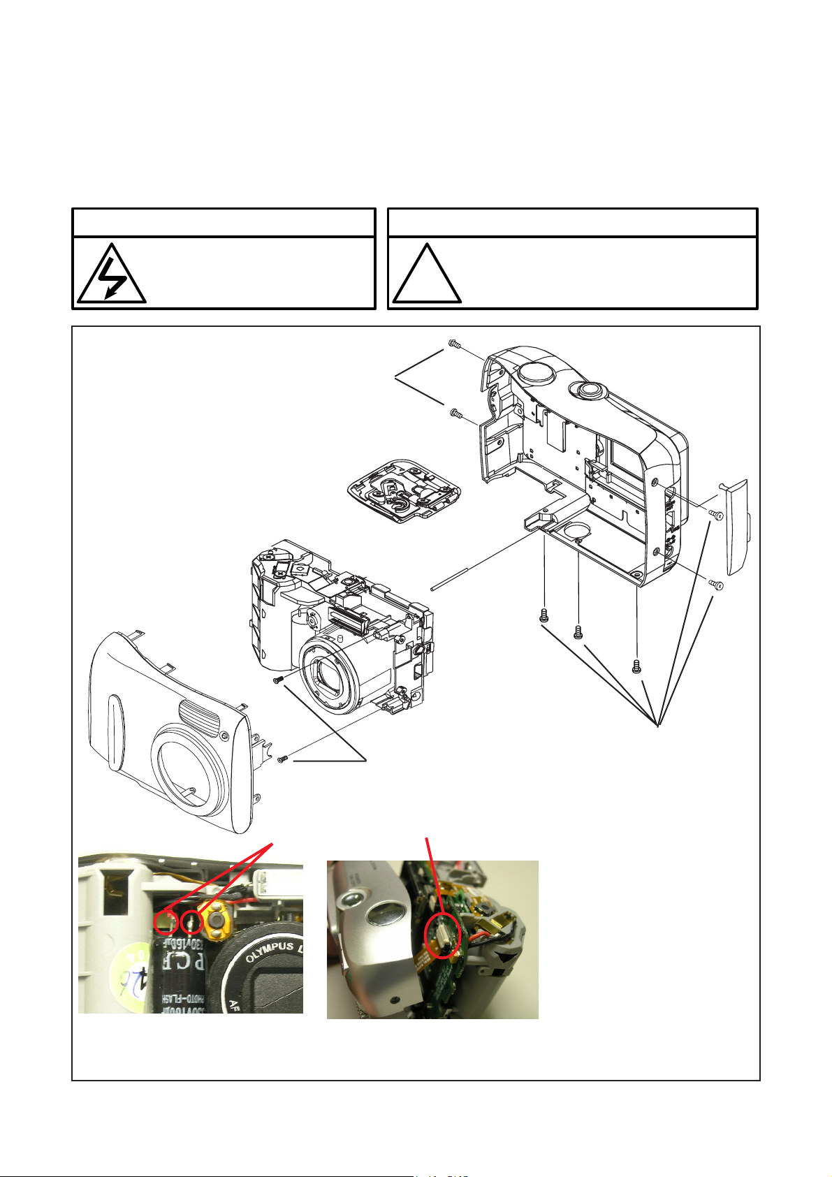
[1] REMOVAL OF Front / BACK Cover And Body
Disassembly perform as follows and assembly perform by reversing the disassembly steps.
Be sure to discharge the main capacitor, then continue to disassembling.
! Beware of electric shock
Danger of electric shock.
Use a discharging tool to remove
the electrical charge before working.
7
2
Notice
The lead free solder is applied to this product.
!
1
Use the lead free solder in working.
8
10
4
O
E
T
VID
OU
USB
DC IN 3.4V
9
6
1
5
1. Screw x 7
2. Front Cover
3
6
3. Discharge
4. Jack Cover
5. Screw x 2
6. FPC from Back Cover
7. Body Frame
8. Back Cover
9. Battery Cover Shaft
10. Battery Cover
B-2 Ver. 1
Page 3

B. DISASSEMBLY AND ASSEMBLY PROCEDUREX-450/D-535ZOOM/C-370ZOOM
[2] REMOVAL OF MAIN PCB,FLASH PCB AND LENS UNIT
28
20
26
27
19
3 5
7
9
6
1.
8
11
29
24
23
25
10
12
21
13
15
22
1. Solder ( LCD )
2. LCD Bracket Clip
3. Tape
4. LCD FPC
2
5. LCD
6. Screw x 2 ( LCD Bracket )
7. LCD Bracket
8. Connector ( Top FPC )
9. Screw x 3 ( Main PCB )
10.Lens FPC
11.Solder ( LED )
12.Solder ( CCD FPC )
13.CCD FPC
14.Solder ( Battery Contact )
15.Main PCB
16.Solder ( Flash Tube )
17.Solder ( Refrector )
18.Solder ( Capacitor )
19.Screw x 2 ( Flash PCB )
20.Flash PCB
21.Tube Rubber
22.Tube
23.Refrector
24.Screw x 3 ( Lens Unit )
25.Lens Unit
26.Screw x 2 ( Battery Contact )
27.Battery Contact
28.Top FPC
29.Capacitor
B-3 Ver. 1
Page 4

[4] DISASSEMBLY OF CCD UNIT
S
U
P
M
Y
L
O
B. DISASSEMBLY AND ASSEMBLY PROCEDURE X-450/D-535ZOOM/C-370ZOOM
Lens
CCD Unit
CCD Rubber
LPF ( Coating side faces to the Lens )
1. Screw x 3 ( CCD Unit )
2. CCD Unit
3. CCD Rubber
4. LPF
5. Isolate Tape
6. 1Z Ring
B-4 Ver. 1
 Loading...