

Page 1

C. ADJUSTMENT METHOD X-350/D-575ZOOM/C-360ZOOM
C. ADJUSTMENT METHOD
[1] TABLE FOR SERVICING TOOLS .......................................................................... C-2
[2] EQUIPMENT ........................................................................................................... C-2
[3] ADJUSTMENT ITEMS AND ORDER ......................................................................C-2
[4] SETUP ....................................................................................................................C-2
[5] CONNECTING THE CAMERA TO THE COMPUTER ............................................ C-3
[6] USB STORAGE INFORMATION REGISTRATION ................................................. C-4
[7] ADJUST SPECIFICATIONS.................................................................................... C-4
1. ZOOM BACKLASH ADJUSTMENT ...................................................................C-4
2. LENS ADJUSTMENT ......................................................................................... C-4
3. AWB ADJUSTMENT ........................................................................................... C-5
4. CCD WHITE POINT DEFECT DETECT ADJUSTMENT ................................... C-5
5. CCD BLACK POINT AND WHITE POINT DEFECT DETECT ADJUSTMENT
IN LIGHTED ........................................................................................................C-5
6. LCD PANEL ADJUSTMENT ...............................................................................C-6
6-1. LCD VcomPP ADJUSTMENT ................................................................... C-6
6-2. LCD VcomDC ADJUSTMENT ................................................................... C-6
7. SETTING DESTINATION ....................................................................................C-6
[8] ADJUSTMENT ITEMS ......................................................................................................C-7
CHECKING OF LENS UNIT ............................................................................................... C-8
GETTING THE BACKLASH DATA .................................................................................. C-11
SIEMENS STAR CHART ............................................................................................................ C-12
C-1 Ver.1
Page 2
C. ADJUSTMENT METHOD X-350/D-575ZOOM/C-360ZOOM
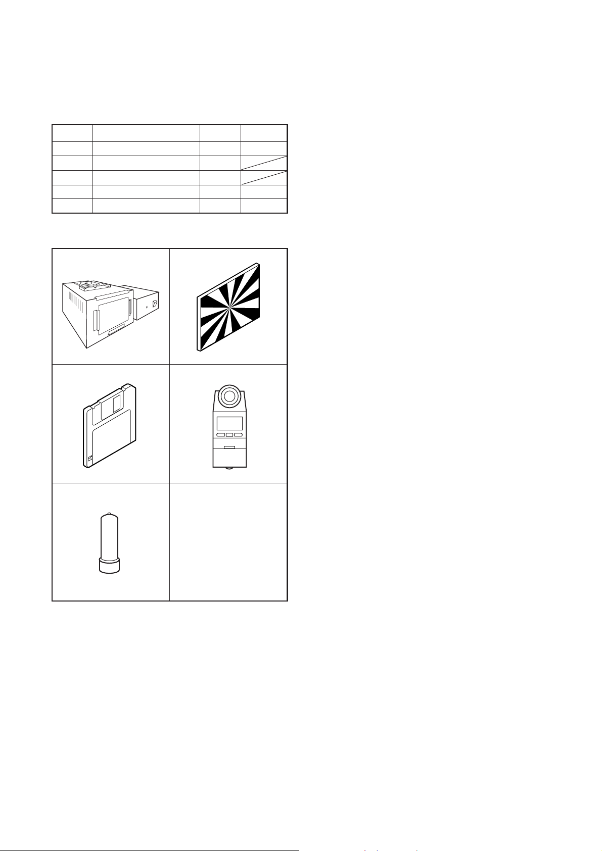
[1] Table for Servicing Tools
Ref. No.
J-1
J-2
J-3
J-4
J-5
Note: J-1 Pattern box (color viewer) is 100 ± 10 VAC only.
Pattern box (color viewer)
Siemens star chart
Calibration software
Chroma meter
Spare lamp
Name Part code
Number
1
1
1
1
1
KC0336
KC0337
KC0339
J-1 J-2
J-3
J-4
[3] Adjustment Items and Order
1. Zoom Backlash Adjustment
2. Lens Adjustment
3. AWB Adjustment
4. CCD White Point Defect Detect Adjustment and Pixel
Map Adjustment
5. CCD Black Point and White Point Defect Detect Adjust-
ment in Lighted
6. LCD Panel Adjustment
6-1. LCD VcomPP Adjustment
6-2. LCD VcomDC Adjustment
7. Setting Destination
Note:
1. If the lens, CCD, board and changing the part in item 1-
5 replace, it is necessary to adjust again. Item 2 should
be carried out after item 1. Item 4 and 5 should be carried out after item 3.
[4] Setup
1. System requirements
Windows 98 or Me or 2000 or XP
IBM ®-compatible PC with pentium processor
CD-ROM drive
3.5-inch high-density diskette drive
USB port
40 MB RAM
Hard disk drive with at least 15 MB available
VGA or SVGA monitor with at least 256-color display
J-5
[2] Equipment
1. Oscilloscope
2. Digital voltmeter
3. AC adaptor
4. PC (IBM ®-compatible PC, Pentium processor, Windows
98 or Me or 2000 or XP)
2. Installing calibration software
1. Insert the calibration software installation diskette into
your diskette drive.
2. Open Explorer.
3. Copy the DscCalDI_130c folder on the floppy disk in the
FD drive to a folder on the hard disk.
3. Installing USB driver
Install the USB driver with camera or connection kit for PC.
4. Pattern box (color viewer)
Turn on the switch and wait for 30 minutes for aging to take
place before using Color Pure. It is used after adjusting the
chroma meter (KC0337) adjust color temperature to 3100
± 20 K and luminosity to 900 ± 20 cd/m
dling the lamp and its circumference are high temperature
during use and after power off for a while.
2
. Be careful of han-
C-2 Ver. 1
Page 3
C. ADJUSTMENT METHODX-350/D-575ZOOM/C-360ZOOM
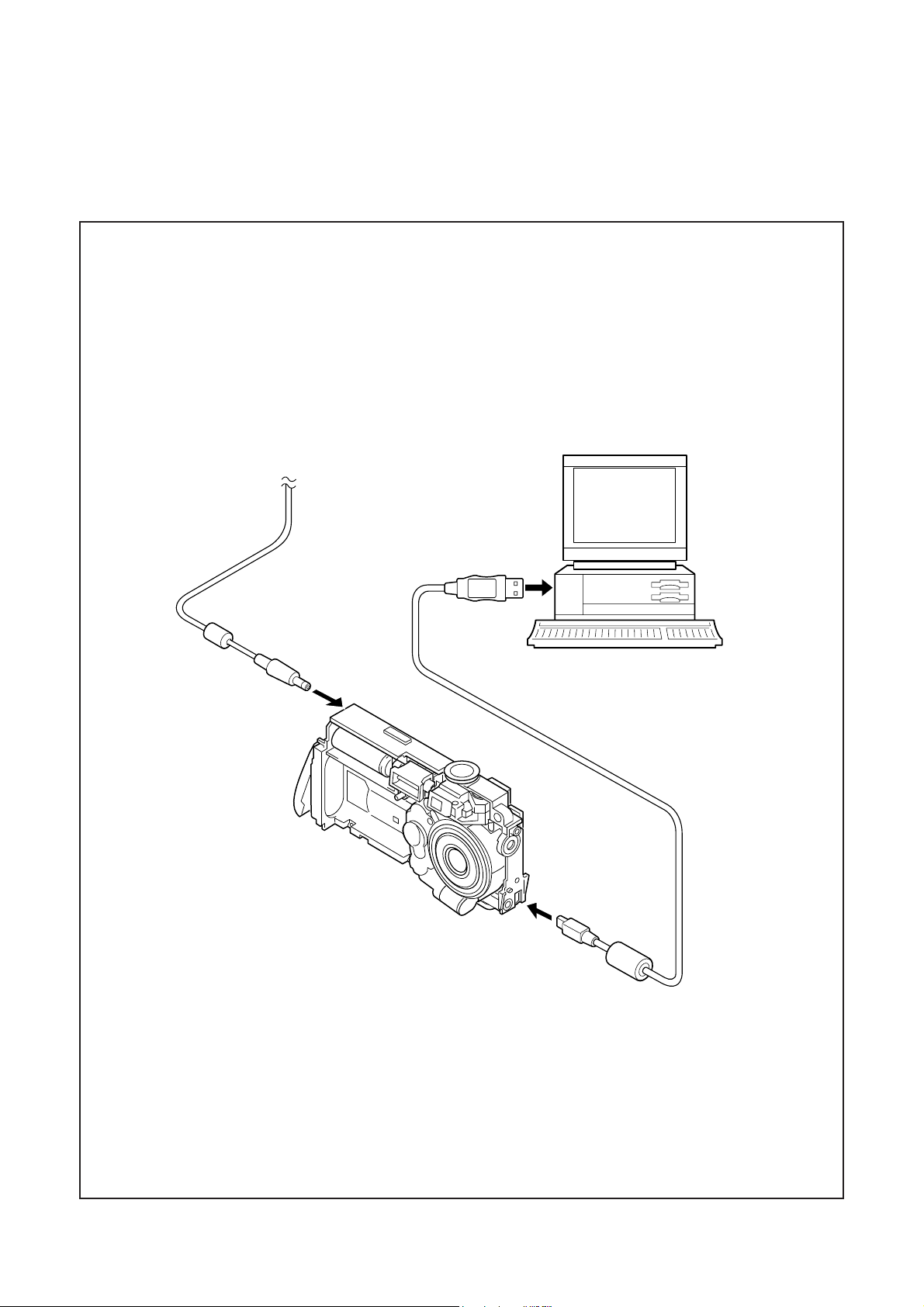
[5] Connecting the camera to the computer
1. Line up the arrow on the cable connector with the notch on the camera's USB port. Insert the connector.
2. Locate a USB port on your computer.
AC adaptor
To USB port
USB cable
C-3 Ver. 1
Page 4
C. ADJUSTMENT METHOD X-350/D-575ZOOM/C-360ZOOM
[6] USB Storage Information Registration
USB storage data is important for when the camera is connected to a computer via a USB connection.
If there are any errors in the USB storage data, or if it has
not been saved, the USB specification conditions will not be
satisfied, so always check and save the USB storage data.
Preparation:
POWER switch: ON
Adjustment method:
1. Connect the camera to a computer. (Refer to [5] Connecting the camera to the computer on the page C-3.)
2. Double-click on the DscCalDi.exe in the DscCalDi130b.
3. Click on the Get button in the USB storage window and
check the USB storage data.
VID: OLYMPUS
PID: X350,D575Z,C360Z
Serial:
Rev. : 1.00
4. Check the Serial in the above USB storage data. If the
displayed value is different from the serial number printed
on the base of the camera, enter the number on the base
of the camera. Then click the Set button.
5. Next, check VID, PID and Rev. entries in the USB storage data. If any of them are different from the values in
3. above, make the changes and then click the corresponding Set button.
[7] Adjust Specifications
1. Zoom Backlash Adjustment
Setting the adjustment mode
1. Open the card cover of the camera.
2. Turn on the power switch. CARD-COVER OPEN will be
displayed in the LCD.
3. Push the QUICKVIEW button and OK button more than 3
seconds simultaneously.
4. Push the right arrow button, and select STORAGE.
5. STORAGE/CONTROL will be displayed.
6. Push the below arrow button, and select CONTROL.
7. Push the OK button.
8. Close the card cover of the camera.
Preparation:
POWER switch: ON
Adjustment method:
1. Double-click on the DscCalDi.exe.
2. Input the two-digit number of the bar code attached to the
lens at the blank which is beside Backlash pulse.
3. Click the Set button on the right side.
2. Lens Adjustment
Calibration
AWB
Focus
UV Matrix
Cal Mode
Cal Data
USB storage
VID
Get
PID
Set
Backrush pulse :
OK
OK
Upload
Firmware
Image
Initialize
EVF
LCD Type
Get
LCD
R Bright
RGB Offset
Tint
VCO
H AFC Test
Serial
Set
Set
Rev.
B Bright
Gain
Phase
Set
Set
Set
VCOMDC
VCOMPP
Setting
Language
Video Mode
Factory Code
Camera
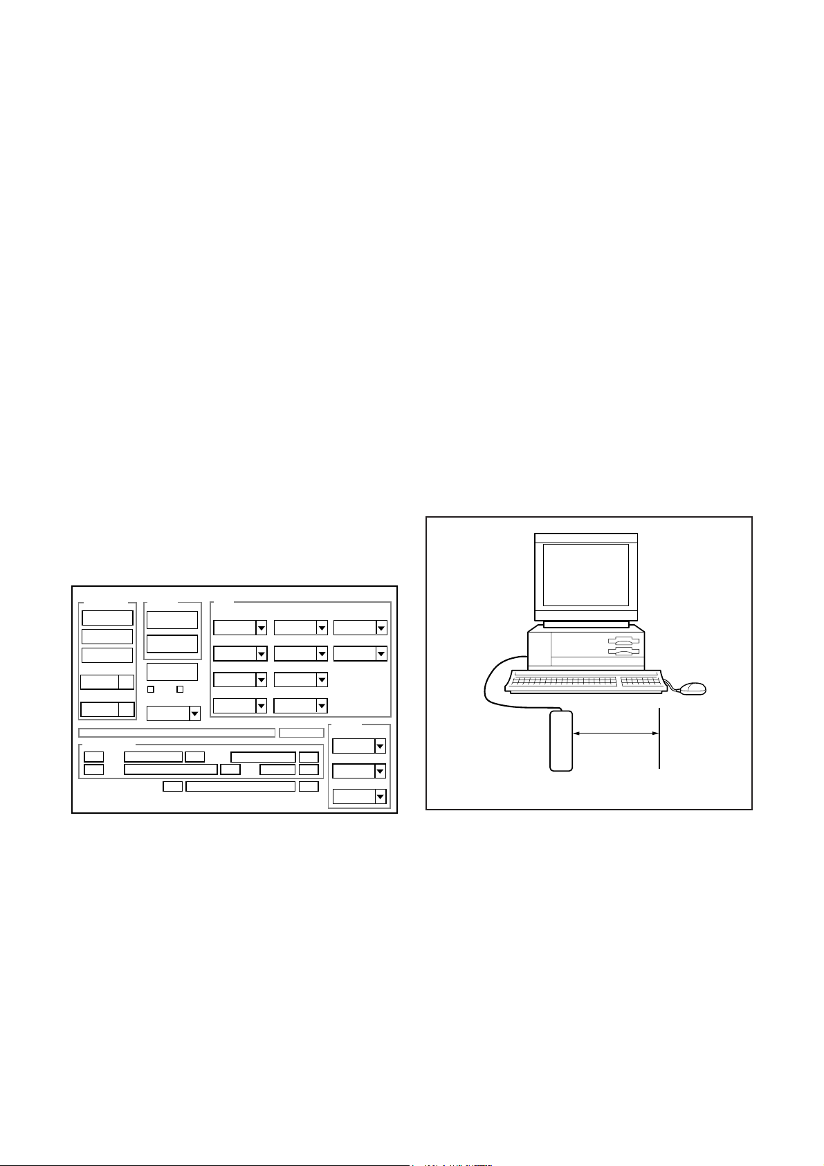
Approx.
60 cm ± 2 cm
Siemens
star chart
Preparation:
POWER switch: ON
Adjustment condition:
Siemens star chart (A3)
Fluorescent light illumination with no flicker (incandescent
light cannot be used.)
Illumination above the subject should be 400 lux ± 10%.
C-4 Ver. 1
Page 5
C. ADJUSTMENT METHODX-350/D-575ZOOM/C-360ZOOM
Adjustment method:
1. Set the siemens star chart 60 cm ± 2 cm so that it becomes center of the screen.
2. Double-click on the DscCalDi.exe.
3. Click the Focus, and Click the Yes.
4. Lens adjustment value will appear on the screen.
5. Click the OK.
Adjustment value determination is effectuated using
PULSE_PR-TO-WIDE, xd0, xd6, xd13 and xd19 values.
The adjustment values fulfill the conditions below, they are
determined as within specifications.
Adjustment value determination
742<=PULSE_PR-TO-WIDE<=885
xd0 = 0 ± 158, xd6 = xd0 ± 80, xd13 = xd6 ± 70,
xd19 = xd13 ± 50
3. AWB Adjustment
4. CCD White Point Defect Detect Adjustment and
Pixel Map Adjustment
Preparation:
POWER switch: ON
Adjustment method:
1. Double-click on the DscCalDi.exe.
2. Select CCD Defect on the LCD Test, and click the Yes.
3. After the adjustment is completed, the number of defect
will appear.
(When adjustment is failed, detect_ng will display.)
4. Click the OK.
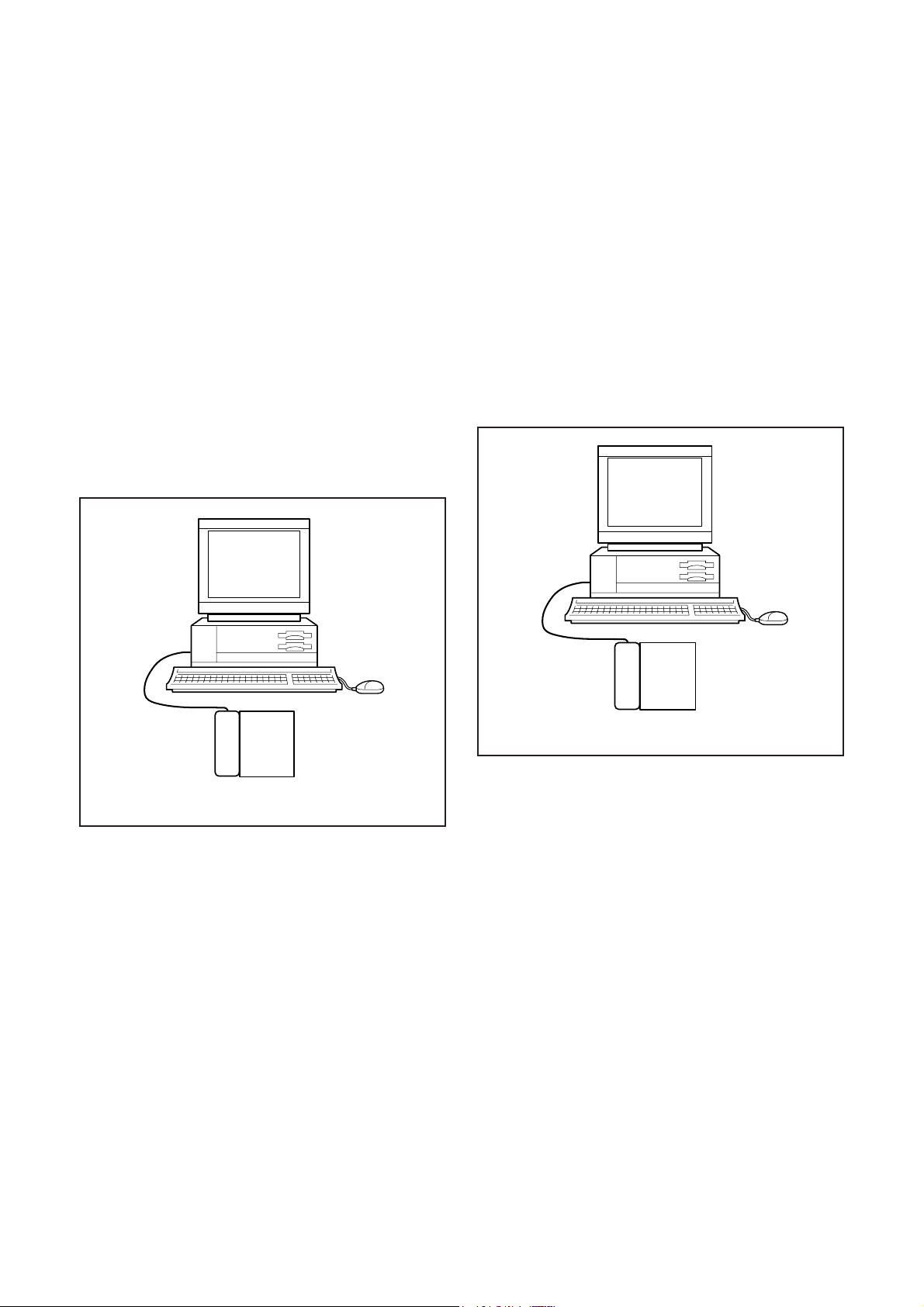
5. CCD Black Point And White Point Defect Detect
Adjustment In Lighted
Camera
Pattern box
(color viewer)
Preparation:
POWER switch: ON
Setting of pattern box:
Color temperature: 3100 ± 20 (K)
Luminance: 900 ± 20 (cd/m
2
)
Adjusting method:
1. Set the camera 0 cm from the pattern box. (Do not enter
any light.)
2. Double-click on the DscCalDi.exe.
3. Click the AWB, and click the Yes.
4. AWB adjustment value will appear on the screen.
5. Click the OK.
Adjustment value determination is effectuated using "AGC"
and "CHECK" values.
If AGC=a1, a2, a3, a4, a5, CHECK=wc0, wc1, wc2 and the
adjustment values fulfill the conditions below, they are determined as within specifications.
Adjustment value determination
a1<1023, a2<1023, a3<1023, a4<1023, a5<1023
wc0=128 ± 2, wc1=128 ± 2, wc2=130 ± 40
Camera
Pattern box
(color viewer)
Preparation:
POWER switch: ON
Setting of pattern box:
Color temperature: 3100 ± 20 (K)
Luminance: 900 ± 20 (cd/m
2
)
Adjusting method:
1. Set the camera 0 cm from the pattern box. (Do not enter
any light.)
2. Double-click on the DscCalDi.exe.
3. Select CCD Black on the LCD Test, and click the Yes.
4. After the adjustment is completed, the number of defect
will appear.
(When adjustment is failed, detect_ng BLACK x, y will
display.)
5. Click the OK.
C-5 Ver. 1
Page 6

C. ADJUSTMENT METHOD X-350/D-575ZOOM/C-360ZOOM
6. LCD Panel Adjustment
[CP1 board (Side B)]
VR501
CL411
CL413
6-1. LCD VcomPP Adjustment
Preparation:
POWER switch: ON
Adjusting method:
1. Double-click on the DscCalDi.exe.
2. Select 0 on the LCD VCOMPP.
3. Adjust LCD VCOMPP so that the amplitude of the CL413
waveform is 5.35 V ± 0.1 Vp-p.
5.35 V
± 0.1 Vp-p
Completing the adjustment mode
1. Open the card cover of the camera.
2. Turn on the power switch. CARD-COVER OPEN will be
displayed in the LCD.
3. Push the QUICKVIEW button and OK button more than 3
seconds simultaneously.
4. Push the right arrow button, and select CONTROL.
5. STORAGE/CONTROL will be displayed.
6. Push the below arrow button, and select STORAGE.
7. Push the OK button.
8. Close the card cover of the camera.
7. Setting Destination
Preparation:
POWER switch: ON
Adjusting method:
1. Double-click on the DscCalDi.exe.
2. Select your destination area on the Factory code.
Note:
The ALL and the Direct Setting are not used.
Do not click them.
Destination List
JO : Japan
UO : North America and Canada
EXO : Europe
PXO : South Korea
GXO : General
CO : China
CL413 waveform
6-2. LCD VcomDC Adjustment
Adjusting method:
1. Adjust LCD VCOMDC so that the amplitude of the CL413
waveform is 4.1 V ± 0.05 Vp-p.
4.1 V
± 0.05 Vp-p
GND
(CL411)
CL413 waveform
C-6 Ver. 1
Page 7

8. Adjustment Items
C. ADJUSTMENT METHODX-350/D-575ZOOM/C-360ZOOM
Adjus tm ent item s
Lens CCD LPF CP-1
1. Zoom Backlash Adjustm ent
2. Lens Adjustment
3 . AW B Ad ju s tm en t
4. CCD White Point Defect Detect Adjustment
5. C C D B lack P o in t a n d W h i te Poin t D e fe c t D e te ct Adju s tm e n t in L i g h te d
6. LC D Pan al Adju s tm en t - - -
7. Setting Destination - - -
Changed repaire parts
--
C-7 Ver. 1
Page 8
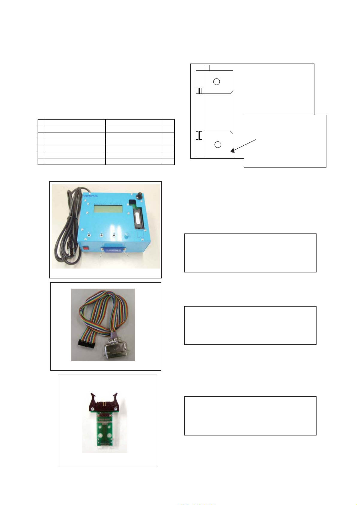
CHECKING OF LENS UNIT
1. Check Item
1)Backlash Pulse of LD
2)LD ERROR Pulse
3)Basklash Pulse of ZOOM
4)ZOOM ERROR Pulse
2. Tools
C.ADJUSTMENT METHOD X-350/D-575ZOOM/C-360ZOOM
FPC-Adaptor 21
PINS
Part No. Description Q'ty
1 KC0331 Lens Checker LCK1 1
2 KC0353 Connector CableP212 1
3 KC0332 Clip Connector 26 1
3 KC0354 Program ROM.v3 1
4 FPC-Adaptor 21PIN 1
(including KC0332)
Lens Checker LCK-1
The last 2 digits are mean-
ing the number of Pin.
080-10
Ex.) 080-10 :10PINS
3. Checking Procedure
Fi x FPC-Adaptors (21 PINS) to ClipConnector26.
Connect Connector Cable P212, Clip Connector
26 and Lens Checker LCK-1
1) AUTO
I. Tum on Lens Checker LCK-1
Initial Setting
II. Set AUTO / MANU SW at AUTO
III.Set Dial SW at 0
IV. S e t C W / C CW SW at C W
LCK-1 Ver.3 0 Auto
PUSH START SW
Connector Cable P212
Clip Connector 26
(0 : Number of Dial SW 0-5)
V. Connect the K FPC to Clip Connectors.
Hold a lens unit by hand, and keep it hor izo nta lly.
VI. Push START SW. (More than 0.2 sec.)
LCK-1 Ver.3 0 Auto
ZOOM RESET
C-8 Ver.1
Page 9

X-350/D-575ZOOM/C-360ZOOM
C.ADJUSTMENT METHOD
When an error occurs, an error is indicated, and it stops.
LCK-1 Ver.3 0 Auto
ZOOM PR CHK
***
* is PR PULSE
LCK-1 Ver.3 0 Auto
ZOOM BACKLASH CHK
ZB *
* is BACKLASH PULSE
LCK-1 Ver.3 0 Auto
ZOOM HANI CHK
ZB ****
**** is OPERATION RANGE PULSE
LCK-1 Ver.3 0 Auto
LD BACKLASH CHK
LB* ZB
* is BACKLASH PULSE
In case of GOOD
LCK-1 Ver.3 0 Auto
PUSH START SW
LB1 D<
GOOD
In case of NG :
LCK-1 Ver.3 0 Auto
PUSH START SW
LB D<
NO GOOD ZM D Err
ERROR is indicated
(The indication which isn’t being explained is the condition
of PR and PI.)
When CW/CCW SW is set at CCW, the automatic check of
the motor chosen with a LD/ZOOM SW is done.
2) Manual
I. Set AUTO/MANU SW at MANU
LCK-1 Ver.3 0 Manu
LD CW
LCK-1 Ver.3 0 Auto
LD D CHK
LB1 D ** ZB
* * is SLIPPAGE PULSE (1st: Set up. 2nd: Set down.)
LCK-1 Ver.3 0 Auto
LD MUGEN CHK
LB1 D ** ZB ***
The contents chosen with the LD/ZOOM SW and the CW/
CCW SW indicated in LCD.
II. Push START SW (More than 0.2 sec.)
LCK-1 Ver.3 0 Manu
LD CW
MOVE
When a motor works, “MOVE” is indicated in LCD.
C-9 Ver. 1
Page 10

C.ADJUSTMENT METHOD X-350/D-575ZOOM/C-360ZOOM
LD Motor
When PI signal 500 pulses (500pps) are changed,LD motor
stops
CW : Turn Out CCW : Tum In
ZOOM Motor
When PI signal 2200 pulses (300pps) are changed, ZOOM
motor stops
CW : W to T CCW : T to W
4. Others
Turn off LCK-1 promptly if something is wrong.
5, ERROR Indication
PI, PR Err : PI or PR Pulse does not change.
LD BK Err : LD BACKLASH PULSE is out of standard.
LD D Err : LD Pulse Error
ZD BK Err : ZOOM BACKLASH PULSE is out of
standard
ZD D Err : ZOOM Pulse Error
C-10 Ver.1
Page 11

X-350/D-575ZOOM/C-360ZOOM
C.ADJUSTMENT METHOD
GETTING THE BACKLASH DATA
If the lens unit was disassembled,the bar code data applied to K-FPC is Invalid. So, it is necessary to get the Backlash
data again in following procedure.
[1] TOOLS
BACKLASH DATA JIG (KC0361)
BACKLASH DATA SOFTWARE
[2] EQUIPMENTS
PC (IBM ®-compatible PC, Pentium processor, Windows 98SE or 2000)
USB Cable
AC adaptor E-7AC
[3] PROCEDURE
1. Connect the K-FPC to the BACKLASH DATA jig.
2. Connect the AC adaptor to the BACKLASH DATA jig and close the card cover.
3. Connect the PC to the BACKLASH DATA jig by USB cable.
4. Start the BACKLASH DATA SOFTWARE.
5. Keep the lens unit horizontally.
6. Click “ZOOM Adj”.
7. The new data will be displayed on the PC. And erase the two-digit number of the bar code attached to the lens unit.
C-11 Ver. 1
Page 12

C.ADJUSTMENT METHOD X-350/D-575ZOOM/C-360ZOOM
SIEMENS STAR CHART
Ver. 1C-12
 Loading...