

Page 1

B. DISASSEMBLY AND ASSEMBLY PROCEDURE
C-120/D-380
B. DISASSEMBLY AND ASSEMBLY
PROCEDURE
[1] REMOVAL OF CABINET BACK, CABINET FRONT AND TB1 BOARD ................ B-2
[2] REMOVAL OF LCD ................................................................................................. B-3
[3] REMOVAL OF CP1 BOARD AND LENS ASSEMBLY ........................................... B-4
B-1
Ver. 1
Page 2
B. DISASSEMBLY AND ASSEMBLY PROCEDURE C-120/D-380
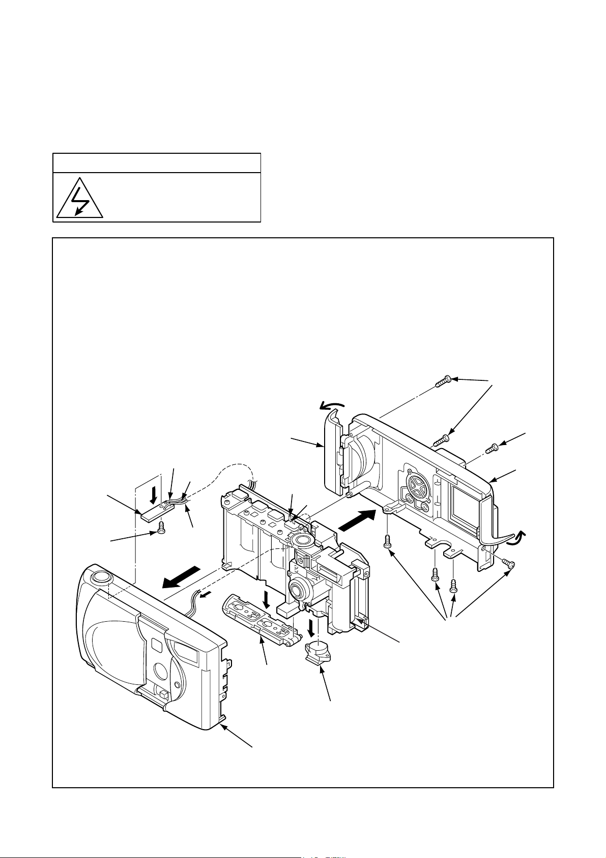
[1] REMOVAL OF CABINET BACK, CABINET FRONT AND TB1 BOARD
Disassembly perform as follows and assembly perform by reversing the disassembly steps.
Be sure to discharge the main capacitor, then continue to disassembling.
! Beware of electric shock
Danger of electric shock.
Use a discharging tool to remove
the electrical charge before working.
12
11
1. Open the cover card.
2. Open the cover jack.
3. Open the cover battery.
4. Two screws 1.7 x 6
5. Five screws 1.7 x 4.5
6. Cabinet back
Brown
Gray
Yellow
7
White
Yellow
7. Cover card
8. Cover battery
9. Cabinet front
10. Stand
11. Screw 1.7 x 3.5
12. TB1 board
4
1
5
6
2
3
5
C5412
Discharge both edge of
8
C5412.
10
9
B-2 Ver. 1
Page 3

[2] REMOVAL OF LCD
1. FPC
2. Remove the solder.
3. LCD
4. Three screws 1.7 x 3.5
5. Holder monitor
B. DISASSEMBLY AND ASSEMBLY PROCEDUREC-120/D-380
4
3
5
1
6. Two screws 1.7 x 3.5
7. Remove the solder.
8. Black
9. Gray
10. White
11. Yellow
12. Black
13. Red
4
2
Red
White
8
9
10
A
11
12
B
13
6
Red
A
B
7
Black
Black
Gray
Red
B-3 Ver. 1
Page 4

B. DISASSEMBLY AND ASSEMBLY PROCEDURE C-120/D-380
[3] REMOVAL OF CP1 BOARD AND LENS ASSEMBLY
1. Screw 1.7 x 4
2. Earth terminal
3. Spacer sheet CP1
4. Two screws 1.7 x 6
5. Connector
6. Spacer wire ST
7. CP1 board
6
Lens
5
7
4
CCD
2
3
1
[4] BOARD LOCATION
TB1 board
CP1 board
B-4 Ver. 1
 Loading...