

Page 1

C. ADJUSTMENT METHOD C-120/D-380
C. ADJUSTMENT METHOD
[1] TABLE FOR SERVICING TOOLS .......................................................................... C-2
[2] EQUIPMENT ..........................................................................................................C-2
[3] ADJUSTMENT ITEMS AND ORDER ..................................................................... C-2
[4] SETUP....................................................................................................................C-2
[5] CONNECTING THE CAMERA TO THE COMPUTER ............................................ C-3
[6] USB STORAGE INFORMATION REGISTRATION ................................................. C-4
[7] ADJUST SPECIFICATIONS ................................................................................... C-4
1. IC501 Oscillation Frequency Adjustment ......................................................... C-4
2. 5.1 V (A) VOLTAGE ADJUSTMENT .................................................................... C-4
3. AWB ADJUSTMENT ............................................................................................ C-5
4. COLOR ADJUSTMENT ....................................................................................... C-5
5. CCD WHITE POINT DEFECT DETECT ADJUSTMENT ....................................C-5
6. CCD BLACK POINT DEFECT DETECT ADJUSTMENT .................................... C-5
7. LCD PANEL ADJUSTMENT .............................................................................. C-6
7-1. LCD H AFC ADJUSTMENT ...................................................................... C-6
7-2. LCD RGB OFFSET ADJUSTMENT .......................................................... C-6
7-3. LCD GAIN ADJUSTMENT ....................................................................... C-6
7-4. LCD BLUE BRIGHTNESS ADJUSTMENT .............................................. C-6
7-5. LCD RED BRIGHTNESS ADJUSTMENT ................................................ C-7
7-6. LCD VCOMPP ADJUSTMENT................................................................. C-7
[8] Lens ADJUSTMENT............................................................................................... C-7
[9] ADJUSTMENT ITEMS ............................................................................................C-8
SIMENS STAR CHART ................................................................................................... C-9
C-1 Ver.1
Page 2
C. ADJUSTMENT METHOD C-120/D-380
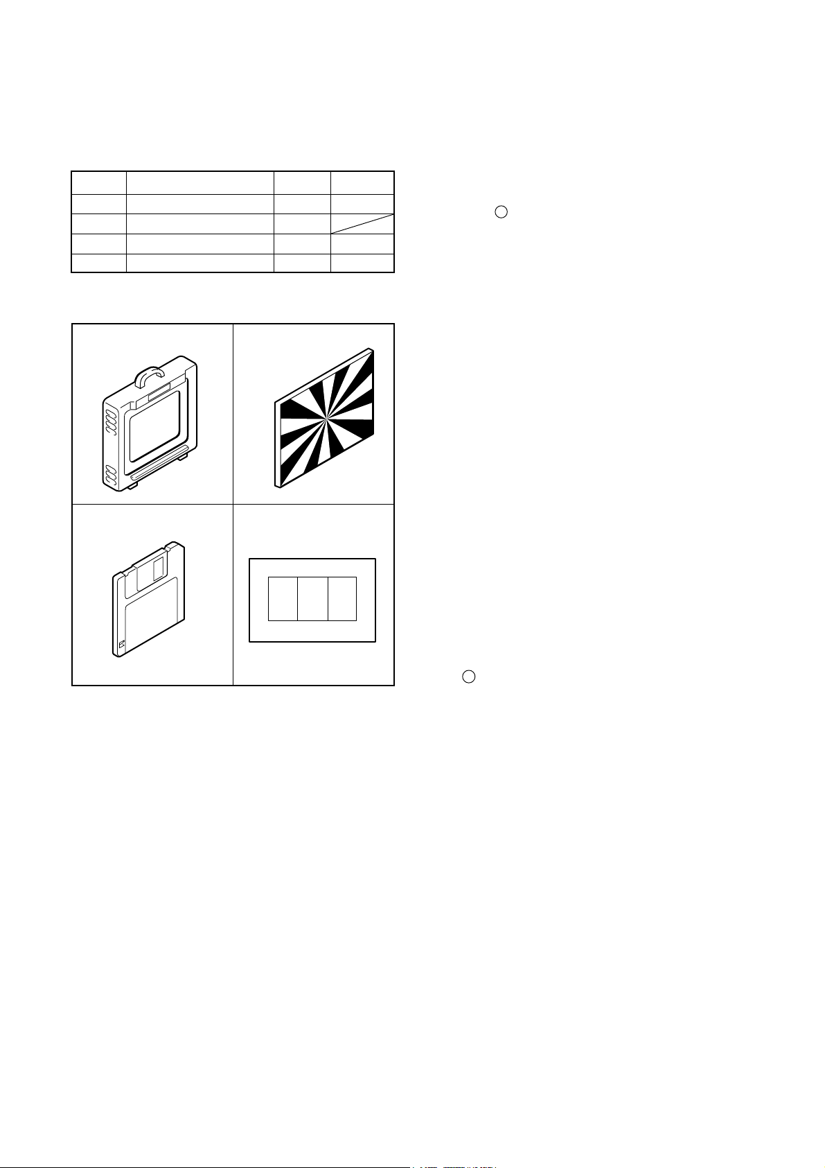
[1] Table for Servicing Tools
Ref. No. Name Part code
J-1
J-2
J-3
J-4
Note: J-1 color viewer is 100 - 110 VAC only.
Color viewer 5,100 K
Siemens star chart
Calibration software
Chart for color adjustment
Number
1
1
1
1
VJ8-0007
VJ8-0189
VJ8-0155
J-1 J-2
J-3
J-4
[2] Equipment
1. Oscilloscope
2. Digital voltmeter
3. AC adaptor
4. PC (IBM R -compatible PC, Pentium processor, Win dow 98 or Me or 2000)
[3] Adjustment Items and Order
1. IC501 Oscillation Frequency Adjustment
2. 5.1 V (A) Voltage Adjustment
3. AWB Adjustment
4. Color Adjustment
5. CCD White Point Defect Detect Adjustment
6. CCD Black Point Defect Detect Adjustment
7. LCD Panel Adjustment
7-1. LCD H AFC Adjustment
7-2. LCD RGB Offset Adjustment
7-3. LCD Gain Adjustment
7-4. LCD Blue Brightness Adjustment
7-5. LCD Red Brightness Adjustment
7-6. LCD VcomPP Adjustment
8. Lens Adjustment
Note:
1. If the lens, CCD, board and changing the part in item 36 replace, it is necessary to adjust again. 3-5 adjust-
ments other than these should be carried out in se quence. Item 6 adjustment should be carried out after
item 3.
[4]. Setup
1. System requirements
Windows 98 or Me or 2000
IBM R -compatible PC with pentium processor
CD-ROM drive
3.5-inch high-density diskette drive
USB port
40 MB RAM
Hard disk drive with at least 15 MB available
VGA or SVGA monitor with at least 256-color display
2. Installing calibration software
1. Insert the calibration software installation diskette into
your diskette drive.
2. Open Explorer.
3. Copy the DscCalDI_128c folder on the floppy disk in
the FD drive to a folder on the hard disk.
3. Installing USB drive
Install the USB drive with camera or connection kit for PC.
C-2 Ver. 1
Page 3
C. ADJUSTMENT METHODC-120/D-380
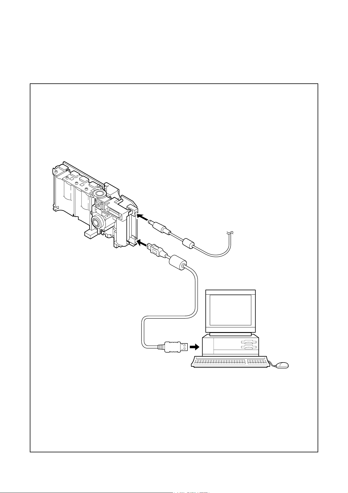
[5] Connecting the camera to the computer
1. Line up the arrow on the cable connector with the notch on the camera's USB port. Insert the connector.
2. Locate a USB port on your computer.
USB cable
To USB port
AC adaptor
C-3 Ver. 1
Page 4

C. ADJUSTMENT METHOD C-120/D-380
[6] USB Storage Information Registration
USB storage data is important for when the camera is connected to a computer via a USB connection.
If there are any errors in the USB storage data, or if it has
not been saved, the USB specification conditions will not be
satisfied, so always check and save the USB storage data.
Preparation:
POWER switch: ON
Adjustment method:
1. Connect the camera to a computer. (Refer to [5] Connecting the camera to the computer on the page C-3.)
2. Double-click on the DscCalDi128c.
3. Click on the Get button in the USB storage window and
check the USB storage data.
VID: OLYMPUS
PID: C-120/D-380
Serial:
Rev. : 1.00
4. Check the “Serial” in the above USB storage data. If the
displayed value is different from the serial number printed
on the base of the camera, enter the number on the base
of the camera. Then click the Set button.
5. Next, check VID, PID and Rev. entries in the USB storage data. If any of them are different from the values in
3. above, make the changes and then click the corresponding Set button.
[7] Adjust Specifications
[CP1 board (Side B)]
S3001
CL310
VR503
VR501
(side A)
CL526
(side A)
CL423
CL425
CL309
CL568
CL415
CL424
(side A)
CL428
Note:
1. Carry out the voltage adjustment with LCD through display mode.
Preparation:
1. Shorten the pin 1 and pin 2 of S3001 (card switch).
2. Shorten the CL309 and CL310 (connection parts of power
switch wires).
3. Insert the smart media.
4. Connect the power, and turn on the LCD switch.
1. IC501 Oscillation Frequency Adjustment
Calibration
AWB
Focus
UV Matrix
Cal Mode
OK
Cal Data
OK
USB storage
VID
Get
PID
Set
Upload
Firmware
Image
Initialize
EVF
LCD Type
LCD
R Bright
RGB Offset
Tint
VCO
H AFC Test
Serial
Set
Set
Rev.
B Bright
Gain
Phase
Set
Set
VCOMDC
VCOMPP
Setting
Language
Video Mode
Measuring Point
Measuring Equipment
ADJ. Location
ADJ. Value
CL526
Frequency counter
VR503
501.5 ± 1 kHz
Adjustment method:
1. Adjust with VR503 to 501.5 ± 1 kHz.
2. 5.1 V (A) Voltage Adjustment
Measuring Point
Measuring Equipment
ADJ. Location
ADJ. Value
Adjustment method:
1. Adjust with VR501 to 5.10 ± 0.05 V.
CL568
Digital voltmeter
VR501
5.10 ± 0.05 V
C-4 Ver. 1
Page 5

3. AWB Adjustment
C. ADJUSTMENT METHODC-120/D-380
W
1/4 H
Camera
All white pattern
Color viewer
Preparation:
POWER switch: ON
Macro switch: normal position
Adjusting method:
1. When setting the camera in place, set it to an angle so
that nothing appears in any part of the color viewer except the white section. (Do not enter any light.)
2. Double-click on the DscCalDi128c.
3. Click the “AWB”, and click the “Yes”.
4. AWB adjustment value will appear on the screen.
5. Click the OK.
4. Color Adjustment
H
Ye
R
1/8 W
Preparation:
POWER switch: ON
Macro switch: normal position
Adjustment method:
1. Set the color adjustment chart to the color viewer, and fix
the camera. (Do not enter any light.) This above chart
shows Ye (yellow) and R (red) portion should apart 1/4
high from edge, and should apart 1/8 width from edge.
2. Double-click on the DscCalDi128c.
3. Click the “UV Matrix”, and Click the “Yes”.
4. Color adjustment values will appear on the screen.
5. Click the OK.
5. CCD White Point Defect Detect Adjustment
Preparation:
POWER switch: ON
Adjustment method:
1. Double-click on the DscCalDi128c.
2. Select “CCD Defect” on the LCD “Test”, and click the
“Yes”.
3. After the adjustment is completed, the number of defect
will appear.
Camera
All white pattern color
viewer and color matrix
adjustment chart
C-5 Ver . 1
Page 6

C. ADJUSTMENT METHOD C-120/D-380
6. CCD Black Point Defect Detect Adjustment 7-1. LCD H AFC Adjustment
Preparation:
POWER switch: ON
Adjusting method:
1. Double-click on the DscCalDi128c.
2. Select 0 on the LCD “H AFC”.
3. While watching the LCD monitor, adjust “H AFC” so that
the edge of the LCD adjustment frame are the same distance from the left and right edge of the LCD screen.
(A = B)
Camera
LCD screen
All white pattern
Color viewer
A
FPC
LCD
adjustment
B
frame
Preparation:
POWER switch: ON
Macro switch: macro position
Adjusting method:
1. When setting the camera in place, set it to an angle so
that nothing appears in any part of the color viewer except the white section. (Do not enter any light.)
2. Double-click on the DscCalDi128c.
3. Select “CCD Black” on the LCD “Test”, and click the
“Yes”.
4. After the adjustment is completed, the number of defect
will appear.
7. LCD Panel Adjustment
[CP1 board (Side A/B)]
S3001
CL310
VR503
VR501
(side A)
CL526
(side A)
CL423
CL425
CL309
CL568
CL415
CL424
(side A)
CL428
7-2. LCD RGB Offset Adjustment
Adjusting method:
1. Adjust LCD “RGB Offset” so that the amplitude of the
CL424 waveform is 3.5 V ± 0.1 Vp-p.
3.5 V
± 0.1Vp-p
CL424 waveform
7-3. LCD Gain Adjustment
Adjusting method:
1. Adjust LCD “Gain” so that the amplitude of the CL424
waveform is 1.9 V ± 0.1 Vp-p.
Note:
7-2. LCD RGB Offset adjustment should always be carried
out first.
1.9 V
± 0.1 Vp-p
CL424 waveform
C-6 Ver. 1
Page 7

C. ADJUSTMENT METHODC-120/D-380
7-4. LCD Blue Brightness Adjustment
Adjusting method:
1. Adjust LCD “B Bright” so that the amplitude of the CL425
waveform is VG ± 0.1 Vp-p with respect to the CL424
(VG) waveform.
Note:
7-2. LCD RGB Offset adjustment and 7-3. LCD Gain adjustment should always be carried out first.
VG
CL424 waveform
VG ±
0.1 Vp-p
7-6. LCD VcomPP Adjustment
Adjusting method:
1. Adjust LCD “VCOMPP” so that the amplitude of the
CL415 waveform is 5.6 V ± 0.1 Vp-p.
5.6 V
± 0.1 Vp-p
CL415 waveform
8. Lens Adjustment
Adjusting method:
1. LH Plate is exchanged for LH Plate2 (VE383000) for the
adjustment with the mark. (It is cut at 10°.)
2. A FC ring should be pressure in the CCD direction by
about 150g. A chart is 1.2m from the front of the lens.
As for the chart, Large Siemens star chart (KC0324) is
used.
CL425 waveform
7-5. LCD Red Brightness Adjustment
Adjusting method:
1. Adjust LCD “R Bright” so that the amplitude of the CL423
waveform is VG ± 0.1 Vp-p with respect to the CL424
(VG) waveform.
Note:
7-2. LCD RGB Offset adjustment and 7-3. LCD Gain adjustment have done.
VG
CL424 waveform
VG ±
0.1 Vp-p
CL423 waveform
3. It turns it until a FC ring is seen from the front of the lens
and put in the CW direction and stuck and it stops.
4. One of the mountains of Roulette of the FC ring is de cided as the mark. (The side of the gate)
5. It hints in the CW direction, and a FC ring is turned in
CCW from the condition with making TFT on condition
and confirming an image in TTL. Then, anabbreviation
peak is found in TTL, and marking is done in LH Plate2.
6. It is returned by five in the CW direction from the mark ing position. That is decided with the start position, and
turning it one indication toward CCW, and shoot one
photography.Repeating this ten times and shoot it
ten photography.
7. An image is confirmed with the PC, and a FC ring is
checked with the best, and screw of LH Plate2 is fas tened and fixed. (A FC ring is always turned in the CCW
direction from the CW direction and checked.)
C-7 Ver. 1
Page 8

[9] Adjustment Items
CCD
LENS
CP1
1. IC501 Oscillation Frequency Adjustment
2. 5.1V(A) Voltage Adjustment
3. AWB Adjustment
4. Color Adjustmen
5. CCD White Point Defect Detect Adjustment
6. CCD Black Point Defect Detect Adjustment
7-1. LCD H AFC Adjustment
7-2. LCD RGB Offset Adjustment
7-3. LCD Gain Adjustment
7-4. LCD Blue Brightness Adjustment
7-5. LCD Red Brightness Adjustment
7-6. LCD VcomPP Adjustment
8. Lens Adjustment
Changed repair parts
Adjustment items
C. ADJUSTMENT METHOD C-120/D-380
○
○
○ ○ ○
○ ○ ○
○ ○ ○
○ ○ ○
○
○
○
○
○
○
○ ○ ○
C-8 Ver. 1
Page 9

C. ADJUSTMENT METHOD C-120/D-380
C-9 Ver. 1
 Loading...