

Oliver 619-20A Owner's Manual

Grand Rapids, Michigan, U.S.A. 49504-5298
USER’S OPERATING AND INSTRUCTION MANUAL
MODEL 619-16A
MODEL 619-20A
MODEL 619-24RA
DOUGH DIVIDERS
0619S20000-CV1

INDEX
Section Description
Document No. Page No.
SAFETY INSTRUCTIONS ------------------------------- 0619S20047 --------------------- 1-1
DESCRIPTION/SPECIFICATIONS ------------------- - 0619S20058------------- --------- 2-1
Description -------------------------------------------------------------------------------------- 2-1
Physical Specifications----------------------------------------------------------------------- 2-1
Electrical Specifications---------------------------------------------------------------------- 2-2
Electrical Wiring Diagrams------------------------------------------------------------------- 2-2
OPERATING INSTRUCTIONS ------------------------- 0619S20048 --------------------- 3-1
Before You Start ------------------------------------------------------------------------------ 3-1
Basic Operation ------------------------------------------------------------------------------- 3-1
MAINTENANCE -------------------------------------------- 0619C20049 --------------------- 4-1
Cleaning ----------------------------------------------------------------------------------------- 4-1
Lubrication -------------------------------------------------------------------------------------- 4-1
Hydraulic Oil Specification ------------------------------------------------------------------ 4-2
Hydraulic Filter Replacement -------------------------------------------------------------- 4-2
Removing The Lid ---------------------------------------------------------------------------- 4-2
Replacing A Plastic Floor ------------------------------------------------------------------- 4-2
Changing The Blades ------------------------------------------------------------------------ 4-3
Replacing The Thrust Plate ---------------------------------------------------------------- 4-3
Replacing The Hydraulic Cylinder -------------------------------------------------------- 4-4
Removing The Motor ------------------------------------------------------------------------- 4-4
Changing The Pump Or Coupling -------------------------------------------------------- 4-5
Replacing The Control Valve -------------------------------------------------------------- 4-5
Adjusting The Pressure Relief On The Control Valve ------------------------------- 4-6
TROUBLESHOOTING ------------------------------------ 0619S20050 --------------------- 5-1
The “End of Stroke Light” Does Not Come On ---------------------------------------- 5-1
The Motor “Hums” But Will Not Start ---------------------------------------------------- 5-1
The Motor Runs But “Stalls” During The Cylinder’s Stroke ------------------------ 5-1
The Motor Has “Stalled” And Cannot Be Restarted --------------------------------- 5-2
The Divider Is Not Cutting Properly ------------------------------------------------------ 5-2
RECOMMENDED SPARE PARTS -------------------- 0619S20051 --------------------- 6-1
REPLACEMENT PARTS SECTION
MAIN FRAME PARTS ----------------------------------- 0619S20052 --------------------- 7-1
Drawing ------------------------------------------------------------------------------------- 7-1
Parts List ----------------------------------------------------------------------------------- 7-2
Continued
REV. 2-26-04
0619S20046 0-1

INDEX (Continued)
REPLACEMENT PARTS SECTION (Continued)
Section Description
Document No. Page No.
COVERS ----------------------------------------------------- 0619S20053 --------------------- 8-1
Drawing ------------------------------------------------------------------------------------- 8-1
Parts List ----------------------------------------------------------------------------------- 8-2
HYDRAULIC PARTS ------------------------------------- 0619S20054 --------------------- 9-1
Drawing ------------------------------------------------------------------------------------- 9-1
Parts List ----------------------------------------------------------------------------------- 9-2
LID PARTS -------------------------------------------------- 0619S20055 -------------------- 10-1
Drawing ------------------------------------------------------------------------------------ 10-1
Parts List ---------------------------------------------------------------------------------- 10-2
ELECTRICAL PARTS ------------------------------------ 0619S20056 -------------------- 11-1
Drawing ------------------------------------------------------------------------------------ 11-1
Parts List ---------------------------------------------------------------------------------- 11-2
PUSHER PARTS ------------------------------------------ 0619S20057 -------------------- 12-1
Drawing ------------------------------------------------------------------------------------ 12-1
Parts List ---------------------------------------------------------------------------------- 12-2
WARRANTY ------------------------------------------------ GEN 040225
WARRANTY PROCEDURE ---------------------------- GEN 040226
RETURNED PARTS POLICY -------------------------- GEN 040227
REV. 2-26-04
0619S20046 0-2

SAFETY INSTRUCTIONS
WARNING
VARIOUS SAFETY DEVICES AND METHODS OF GUARDING HAVE BEEN
PROVIDED ON THIS MACHINE. IT IS ESSENTIAL HOWEVER THAT THE MACHINE
OPERATORS AND MAINTENANCE PERSONNEL OBSERVE THE FOLLOWING
SAFETY PRECAUTIONS. IMPROPER INSTALLATION, MAINTENANCE, OR
OPERATION OF THIS EQUIPMENT COULD CAUSE SERIOUS INJURY OR DEATH.
1. Before attempting to operate your divider read this manual. Never allow an
untrained person to operate this machine.
2. Make sure that the machine is only connected to a properly grounded electrical
supply source of sufficient capacity for the load the divider will put on it. Always
unplug the machine when it is not in use.
3. Always make sure the machine has been disconnected from the power supply before
cleaning or servicing.
4. All guards must be in place before starting the machine.
5. Keep your hands away from the moving parts of the machine.
6. Use only proper replacement parts.
7. Do not wear loose fitting clothing. Shirt tails should be tucked in.
8. In addition to these general safety instructions, also follow the more specific safety
instructions given for the different areas of the machine in the operating instructions.
DO NOT USE FOR OTHER THAN ORIGINALLY INTENDED PURPOSE.
0619S20047 1-1
WARNING

THIS PAGE WAS INTENTIONALLY
LEFT BLANK.
GEN020319
DESCRIPTION/SPECIFICATION
Description
The Oliver divider consists of a hopper which can be loaded with dough from a minimum
of ten and one half pounds up to forty-five pounds. The lid and hopper are made of
heavy cast aluminum. The moveable hydraulic floor of the hopper is made of a
collection of food grade plastic plates which, when moved upward, will compress the
dough until it completely fills the remaining area. At this point a group of stainless steel
knives come between the plates cutting the dough into equal weight, easy to use pieces.
This machine is ideal for pizza and bakery operations and is mounted on four casters for
easy movement about the work area. The divider can divide pieces as small as seven
ounces, on a 24 part divider, to as large as forty five ounces, on the 16 part divider. See
below for specific maximums.
The hydraulic pump is powered by a two horse power, totally enclosed motor. The
system has a built-in four and one half gallon hydraulic oil tank making the machine
totally self contained.
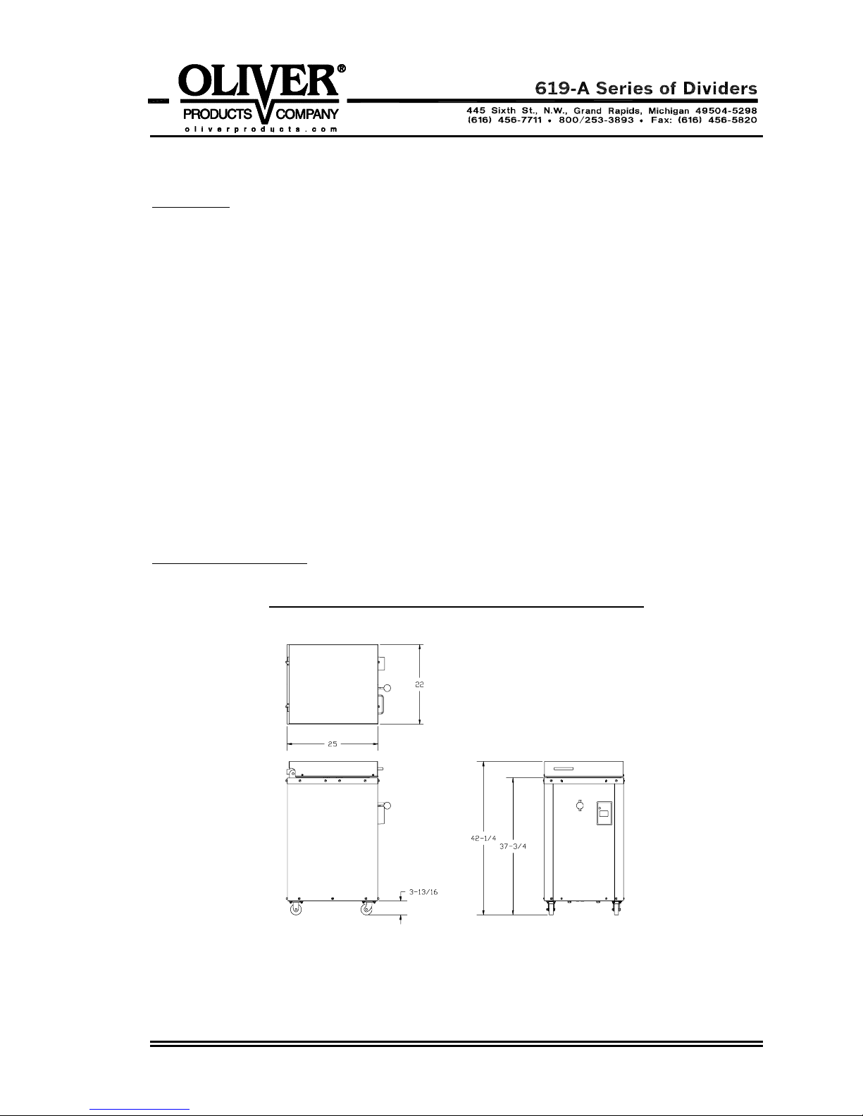
Physical specifications
OVERALL MACHINE DIMENSIONS
0619S20058 2-1
Physical specifications (continued)
Net Weight:
Approximately 455 pounds.
Shipping Weight:
Approximately 500 pounds.
Product Capacities:
Fill Capacity (approximate) = 10-1/2 to 45 pounds
Divided piece Size (approximate):
16 part dividers = 10-1/2 to 45 ounces
20 part dividers = 8-1/2 to 36 ounces
24 part dividers = 7 to 30 ounces
Electrical Specifications
2 Horse Power, 1 phase, 60 hertz, 230 Volts AC, 10 Amps.
2 Horse Power, 3 phase, 60 hertz, 208 Volts AC, 6.5 Amps.
2 Horse Power, 3 phase, 60 hertz, 230 Volts AC, 6.2 Amps.
2 Horse Power, 3 phase, 60 hertz, 460 Volts AC, 3.1 Amps.
Others consult factory
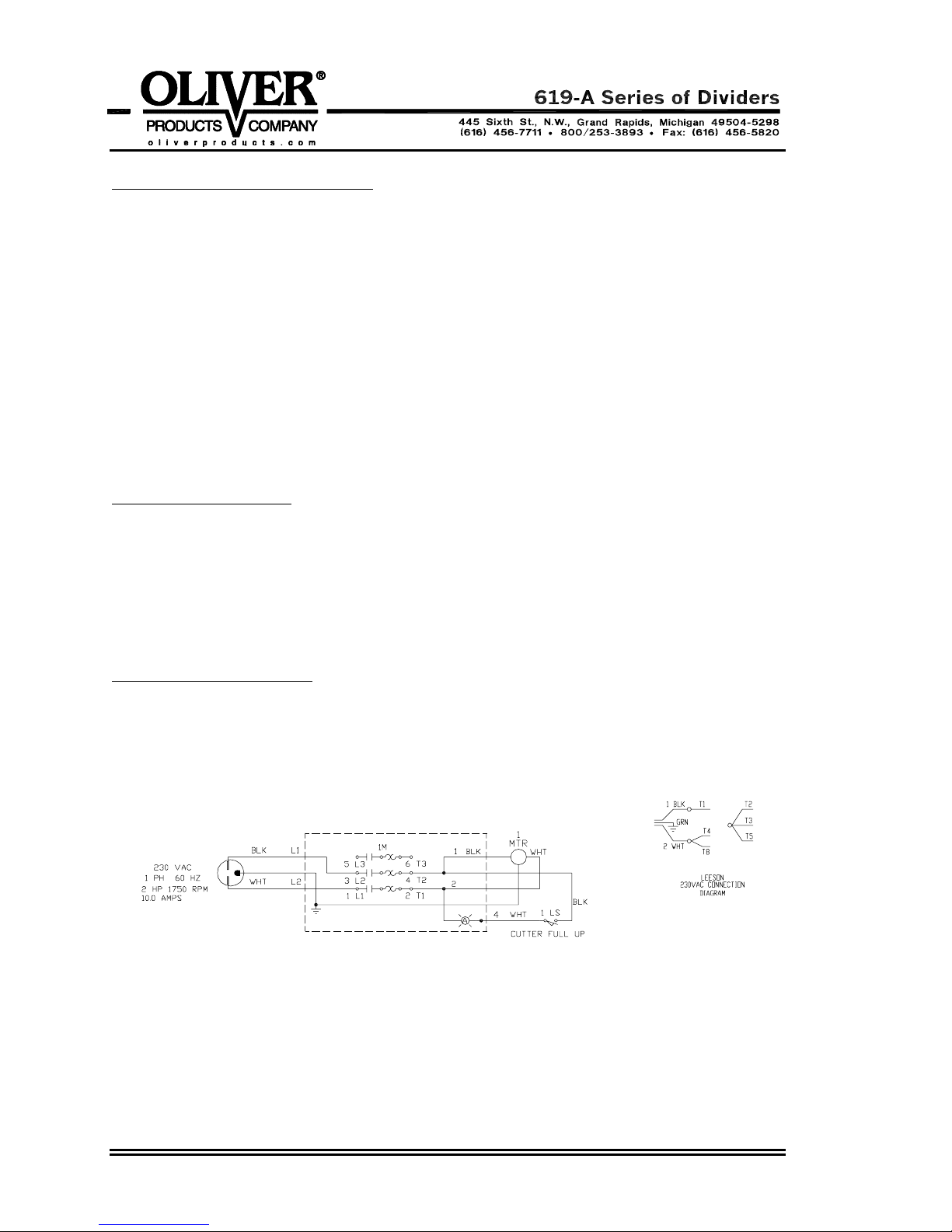
Electrical Wiring Diagrams
1 ph, 60 hz, 230 VAC
0619S20058 2-2
Continued
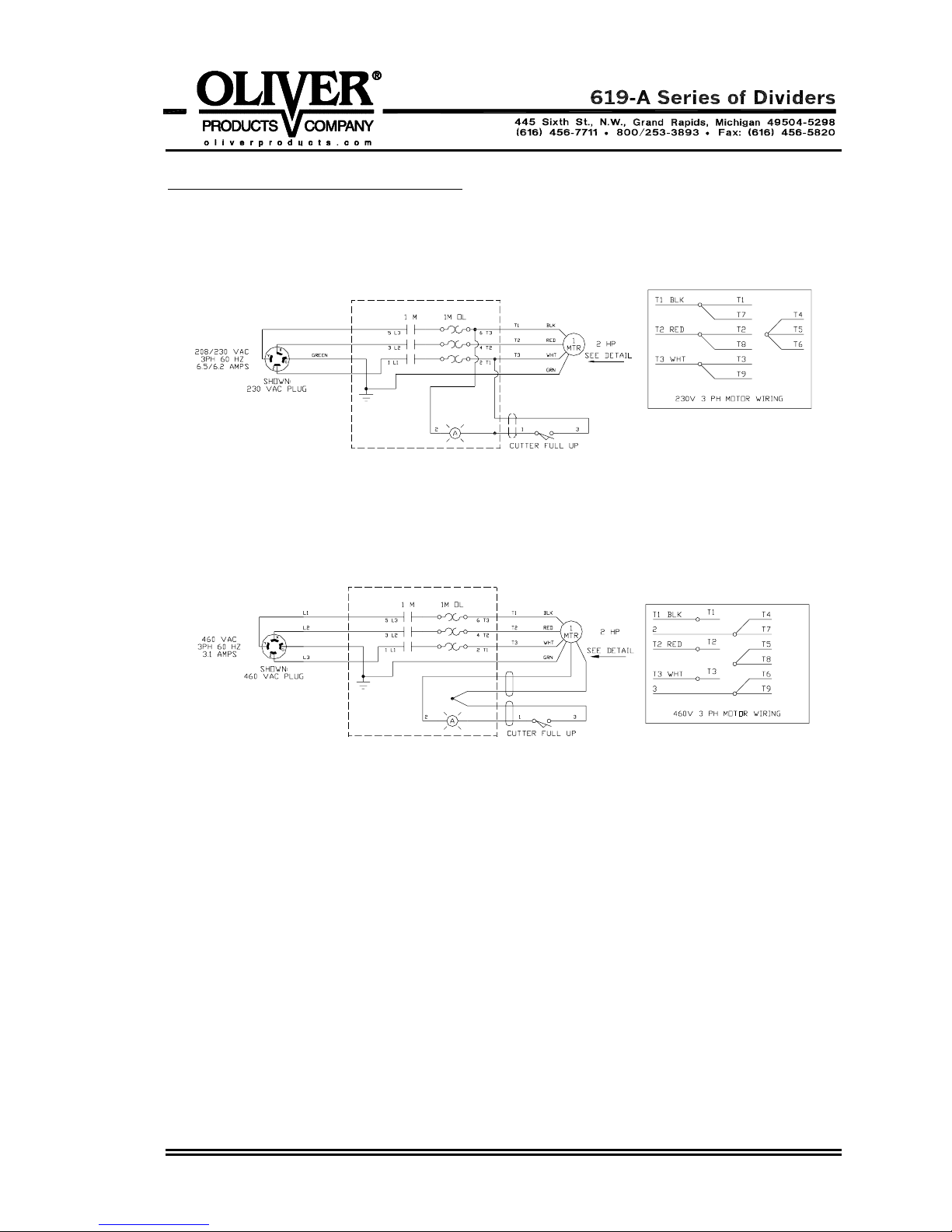
Electrical Wiring Diagrams (Continued)
3 ph, 60 hz, 208/230 VAC
3 ph, 60 hz, 460 VAC
0619S20058 2-3
OPERATING INSTRUCTIONS
Before You Start
CAUTION
THE DIVIDER SHOULD ONLY BE PLUGGED INTO AN OUTLET
WITH THE SAME VOLTAGE AS STATED ON THE NAMEPLATE
Before starting a new divider with THREE PHASE electrical power for the first time you
should check to see if the motor is running in the correct direction. Remove the front
cover by removing the four thumbscrews which secure it; you will also have to remove
the handle from the directional control lever before removing the front cover. Once the
cover has been removed you should be able to see the fan end of the motor on your
divider, this fan MUST rotate in a clockwise direction.
CAUTION
EXTENDED RUNNING OF A DIVIDER WITH THE MOTOR ROTATING
IN THE INCORRECT DIRECTION WILL SEVERELY DAMAGE THE
HYDRAULIC PUMP OF YOUR DIVIDER.
If the motor is rotating in the incorrect direction turn the machine off, disconnect it from
the power supply and have a qualified electrician reverse two of the three power wires in
the plug at the end of the power cord. DO NOT move the ground, (green), wire.
WARNING
ALWAYS HAVE ELECTRICAL WORK DONE BY QUALIFIED ELECTRICIANS.
Recheck the divider making sure that it is now running in the correct direction, (clockwise
looking at the fan end of the motor).
CAUTION
MOTOR ROTATION SHOULD BE CHECKED EVEN IF THE
DIVIDER IS ONLY MOVED TO A DIFFERENT POWER OUTLET
IN THE SAME ROOM
Basic Operation
• Start by weighing out a piece of dough, which, when divided by the number of
compartments available on your divider, will provide you with the desired end weight.
For example: a thirty pound piece of dough after division on a twenty-four part
divider will yield twenty-four, twenty ounce pieces, perfect for molding into one and a
quarter pound loaves of bread.
0619S20048 3-1

Basic Operation (Continued)
• Lower the floor of the hopper before attempting to open the lid of the divider.
• Open the lid and load the preweighed dough into the hopper. Spread the dough
over the floor of the hopper making it approximately the same height, this is done to
eliminate large air pockets and to insure equal division of the dough.
• Close and hold the lid down until dough compression has been started, (see the next
step).
• With the machine running grasp the control valve handle and lift it to start the floor of
the hopper up. Hold it in this position until the light on the starter switch box comes
on, this means that the upward stroke has stopped and that division is complete. Let
loose of the valve handle when you see the light come on.
• Press the control valve handle down slightly before opening the lid.
• The dough may be ejected by lifting the control valve handle to bring the plastic
floors of the dough compartments level with the top of the hopper.
• We suggest that the cut pieces of dough be removed as soon as possible to prevent
them from sticking together.
• Return the floor of the hopper to its lowest position by pushing down on the control
valve handle. When complete this will allow filling of the machine for the next cycle.
• The above process may now be repeated.
WARNING
NEVER
LEAVE DOUGH IN THE MACHINE; RISING DOUGH MAY
CAUSE EXPLOSIVE PRESSURES TO DEVELOP.
0619S20048 3-2
MAINTENANCE
WARNING
ALWAYS MAKE SURE THE MACHINE HAS BEEN DISCONNECTED
FROM THE POWER SUPPLY BEFORE CLEANING OR SERVICING.
Cleaning
The exterior and contact surfaces should be cleaned daily using common cleaners. The
knives should be extended for easier cleaning. This can be done by placing the cleaning
separator, furnished with the machine, IN THE CENTER OF THE HOPPER straddling
the knives. Close the lid and bring the floor of the hopper up until the light on the manual
starter is on, lower the floor slightly. Open the lid and disconnect the divider from the
power supply. Clean the knives and plastic compartment floors of all dough build-up.
CAUTION
IF NOT CLEANED A BUILD-UP OF DRIED DOUGH BETWEEN THE
PLASTIC FLOORS AND THE KNIVES COULD DAMAGE THE DIVIDER.
In addition to the general cleaning discussed above, it is important that you check for
and remove scraps of dried dough from between the blade holder and the bottom thrust
plate. This can be done by first extending the knives as described above and then by
removing the front and rear covers from the machine by removing the eight thumb
screws and the control valve handle knob. This will allow access to the blade holder
area, which can then be cleaned of all dried scraps of dough. When finished replace the
covers and knob.
CAUTION
FAILURE TO CLEAN DRIED DOUGH FROM THE BLADE HOLDER AND
THRUST PLATE COULD RESULT IN SEVERE PUSHER DRIVE DAMAGE.
Occasionally, as required, you should also remove the build up of flour and dough
particles in the base of the machine around the motor.
Lubrication
The machine requires no lubrication but the oil level in the hydraulic system should be
checked periodically. To check the oil level remove the rear cover by removing the four
knobs which secure it to the divider, then remove the tank breather/cap and determine
where the top of the oil is in relation to the top surface of the tank. Fill with oil to within
approximately one inch of the top surface. If necessary add HYDRAULIC OIL
it to the proper level, DO NOT OVERFILL
. In addition to the above we advise replacing
to return
the hydraulic oil in the system approximately every three years.
0619S20049 4-1
Hydraulic Oil Specification
The hydraulic oil used in your divider should be made of good quality base stocks
compounded with the following additives: antiwear, antioxidation, antifoaming, and
antirust. In addition it should be an “ISO” viscosity grade No. 32.
Hydraulic Filter Replacement
At least once a year the throw-away filter on the hydraulic system should be replaced,
more often when under heavy use. To replace the filter remove the front cover, unscrew
the old filter and replace it with a new one. The filter is located on the return line near
the front of the tank.
Removing The Lid
• Remove the lid cover by removing the four screws, which secure it in position.
• Open the lid as far as it will go.
• Release the tension on the two large torsion springs by moving the long leg of the
spring to the side and out from behind the bracket.
WARNING
USE CARE AS THE LID WILL DROP ONCE THE SPRING TENSION
HAS BEEN REMOVED.
• Close the lid and remove the right hand snap ring from the lid hinge pin and push the
pin to the left to remove it.
• Reassemble by reversing the above steps.
Replacing A Plastic Floor
• Open the lid and raise the bottom of the hopper.
• Turn the machine off and disconnect it from the power supply.
• Remove the front and rear panels to gain access to the pusher components.
• Remove the nut securing the plastic floor and upright to the thrust plate.
Continued
0619S20049 4-2
 Loading...