

Page 1

Walker, Michigan, U.S.A. 49534-7564
USER’S OPERATING AND INSTRUCTION MANUAL
MODEL 1908MX2
AUTOMATED PACKAGING SYSTEM
1908S20078CV
Page 2

Page 3

Page 4

INDEX
INTRODUCTION AND DESCRIPTION………………………………. PG. 1-1
INSPECTING…………………………………………………………….. PG. 1-2
SAFETY..............................................……………………..………….. PG. 1-3
MACHINE PLACEMENT………………………………………..……… PG. 1-4
MACHINE COMPONENTS…………………………………………….. PG. 1-5
START-UP & OPERATION………..…………………………………… PG. 1-10
TECHNICAL SPECIFICATIONS....................................................... PG. 1-13
CLEANING AND MAINTENANCE....................…..............…........... PG. 1-14
TROUBLE SHOOTING......................................…......................….. PG. 1-18
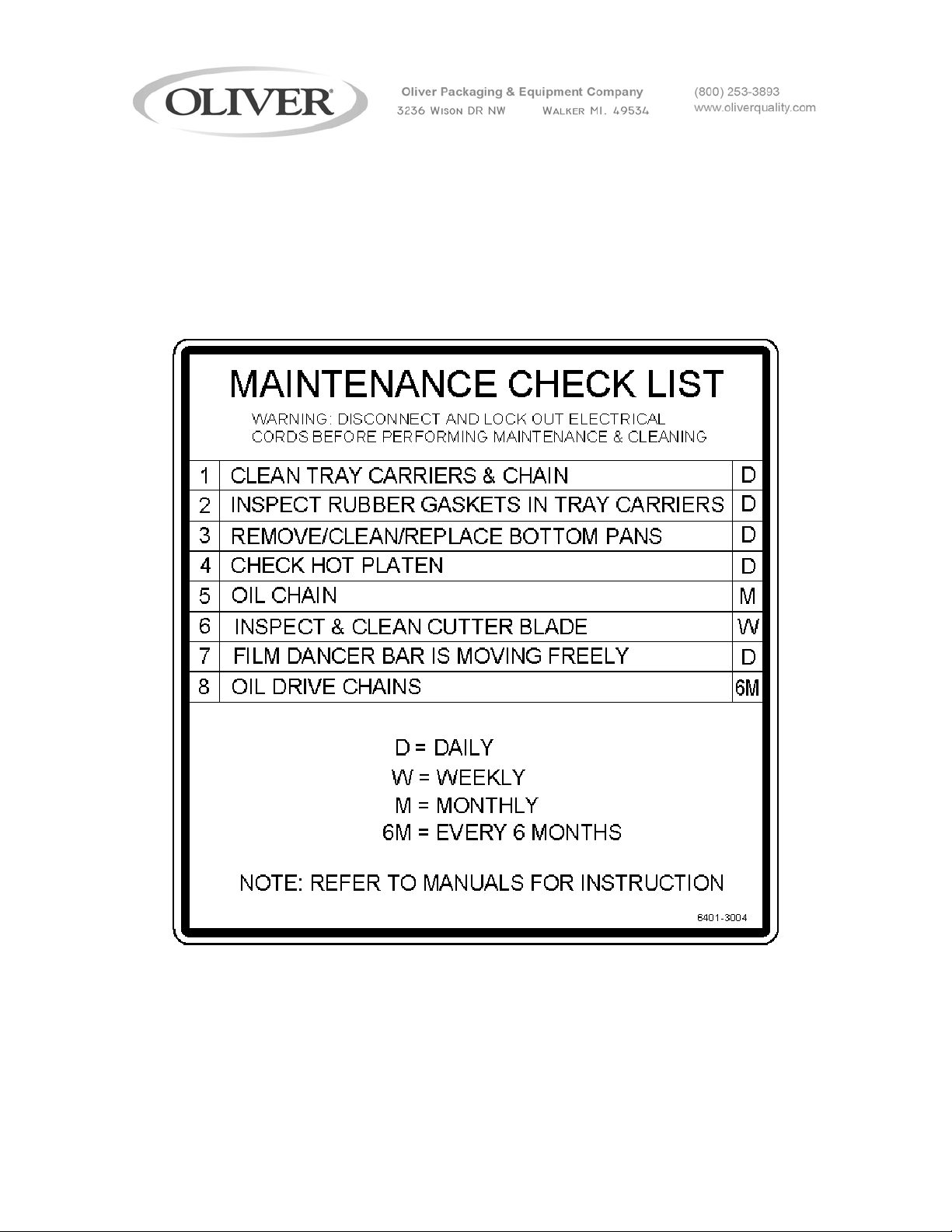
MAINTENANCE CHECKLIST……....................…..............….......... PG. 2-1
ASSEMBLY DRAWINGS & PARTS LISTS..………………………... PG. 3-1
ELECTRICAL……………………………………………………………. PG. 4-1
WARRANTY...................…............................. GEN 050816
WARRANTY PROCEDURE..........….............. GEN 050817
RETURNED PARTS POLICY......................... GEN 050818
1908S20073
Page 5
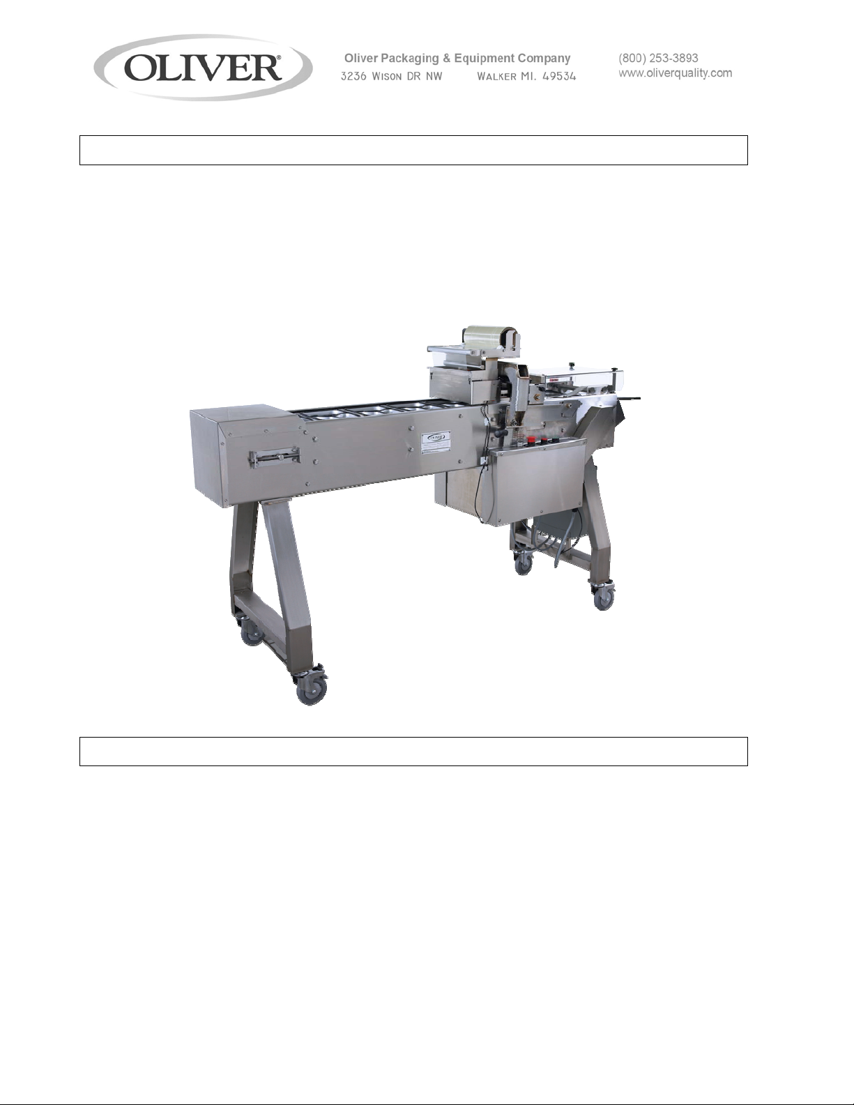
QUICK SPECS
Weight 330 lbs
Overall Dimensions 30” W x 64” L x 50” H
Loading Station 3 tray carriers
Electrical 1 phase, 60 Hz, 115 VAC, 15 amps
INTRODUCTION AND DESCRIPTION
The OLIVER Model 1908 Lidder has been designed and manufactured to provide a high
quality machine that is a cost effective approach to producing film lidded trays. The
machine can be operated with a 120 V.A.C. outlet. The Model 1908 is an automated
system capable of producing a high volume, but it is easy to operate and requires
minimal space.
The machine consists of a conveyor system that transports the filled trays; a film feed
system, a heated platen and a film cutter unit. These are all packaged together in a
stainless steel framework that also houses all the necessary controls. The conveyor is
intermittent motion and is capable of running speeds of 20 to 27 packages per minute.
1908S20074
1-1
Page 6
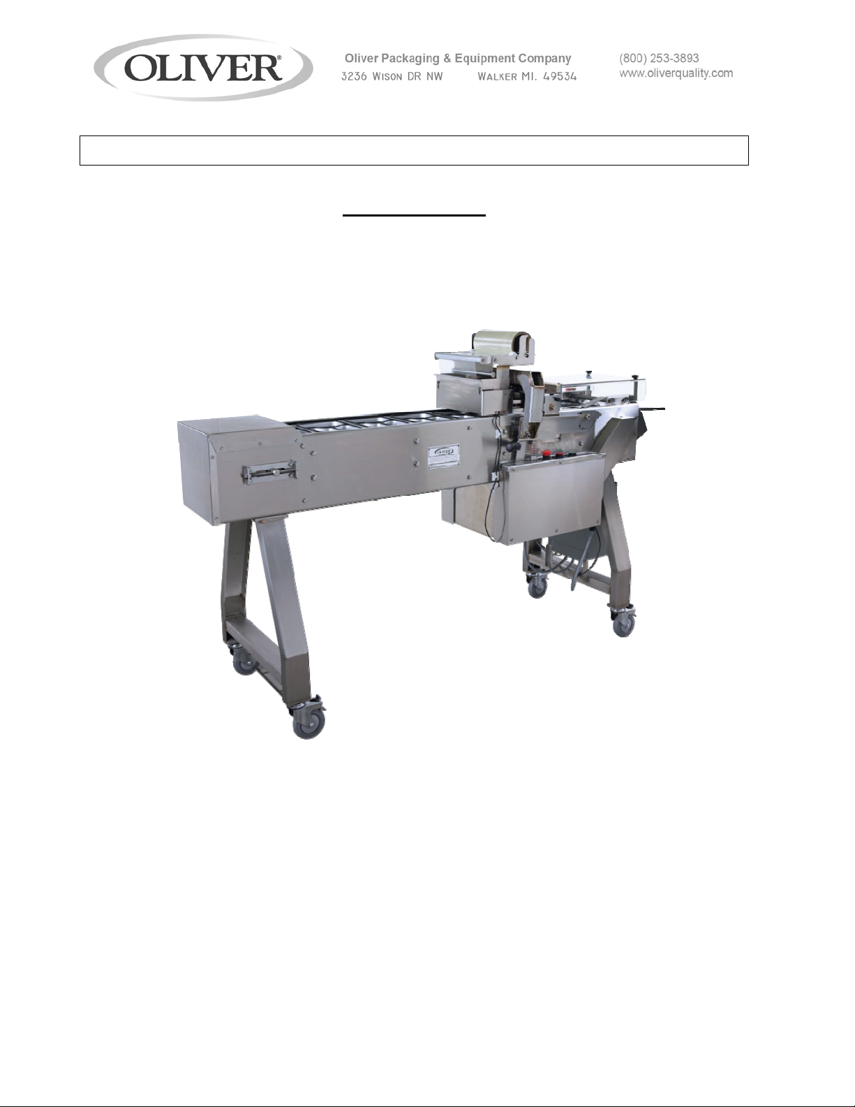
INSPECTING
MODEL 1908
Upon receipt of Machine, inspect the exterior for damage. If damage is noted,
Indicate damage on the Freight Bill and immediately contact the freight Carrier and
notify them of the damage. Have a freight claim filed. This must be done at the
Recipient’s location and not at the Shipper’s Location.
Remove the tie-downs that hold machine to the skid. Lift the machine
off the skid in a safe manner. Remove tape and tie bands that were
used to hold components for shipment.
1908S20074
1-2
Page 7
SAFETY
Various safety devices and methods of guarding have been provided on this machine.
Do not operate the machine with guards removed and do not tamper with safety
devices. It is essential that machine operators and maintenance personnel observe the
following safety precautions. Improper installation or operation of this equipment may
cause injury to personnel or damage to equipment.
• Before operating the OLIVER Model 1908 Lidder read through this manual. Never
allow an untrained person to operate this machine
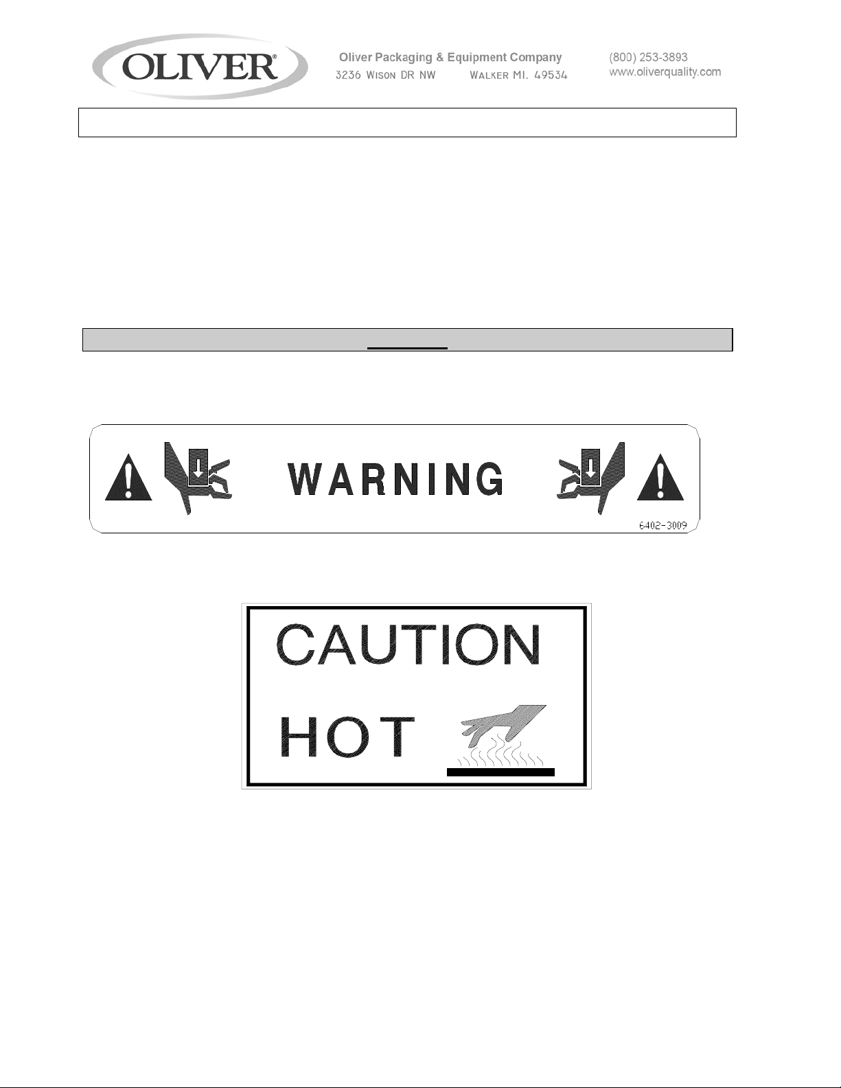
WARNING
• WARNING PINCH POINT: Keep hands out of machine. Always be sure the
machine has been unplugged from power before cleaning or servicing.
• CAUTION HOT: The heater platen and parts around it are very HOT! Caution must
be used to protect yourself and others.
• In addition to these general safety instructions, follow the specific instructions given
throughout this manual.
1908S20074
1-3
Page 8
MACHINE PLACEMENT AND UTILITIES
MODEL 1908
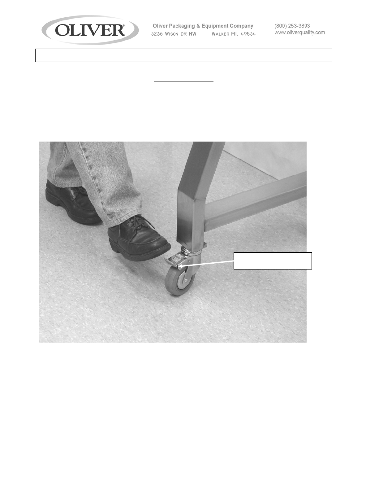
Decide on a suitable location for the machine. This location should have ample room to
work around all sides of the machine. Once the machine is in the location where it will
be used, the brakes on the casters should be locked by stepping down on the brake
locking lever. To unlock, lift the lever with your foot. Do not attempt to move machine
with casters in locked position.
LOCKING LEVER
The machine operates on 120 V.A.C., 60 Hz, 15 Amp electrical power. It is
recommended that this power be supplied by an overhead drop to prevent the cord from
becoming a trip hazard.
1908S20074
1-4
Page 9
g
MACHINE COMPONENTS
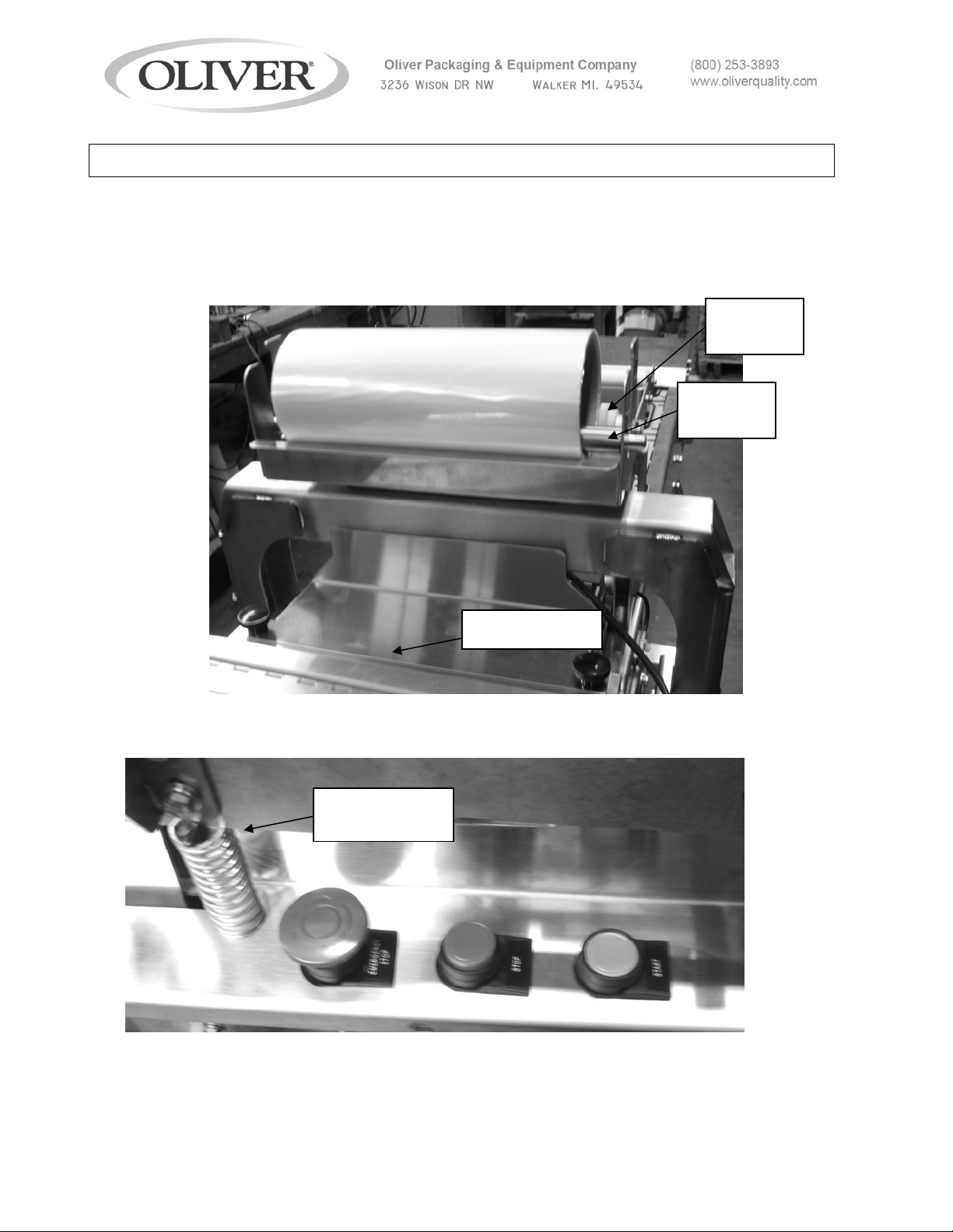
Before proceeding further, take a moment to familiarize yourself with the
identification of the machine components as shown in the illustrations below.
Film Roll Holder with Film Roll and Roll Weight Installed.
Film Roll
Guide
Film Roll
Weight
Emergency Stop, Stop, and Start Buttons
Heat Platen
Lift Sprin
Heat shield
1908S20074
1-5
Page 10
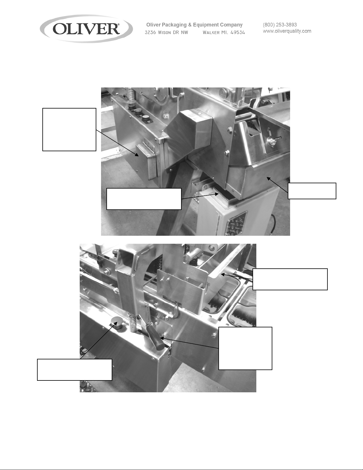
Drive and Platen Release Locations and Speed Control Location
Conveyor
release knob
(Under
Cover)
Rear Emergency
Stop Button
Speed Control knob
Bottom Pan
(Under Cover)
In-feed guard (with
safety switch)
Heater Platen
release lever
(Pull to
release)
1908S20074
1-6
Page 11
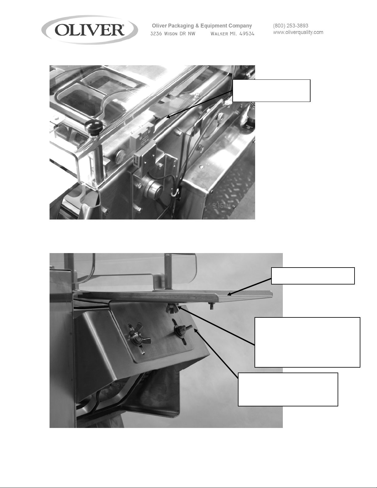
Out feed or discharge area
Discharge Cover
(with safety switch)
DISCHARGE TABLE
THESE WING NUTS
ALLOW FOR MOVING THE
DISCHARGE TABLE IN
AND OUT TO CLEAR THE
TRAY CARRIERS
WING NUTS
LOOSEN TO ADJUST
TABLE UP OR DOWN
1908S20074
1-7
Page 12

Tray Carriers
Film Cut-Off
RUBBER GASKET
TRAY CARRIER
DRIVE SPROCKET
CUTTER BLADE
CUTTER ASSEMBLY
1908S20074
1-8
Page 13
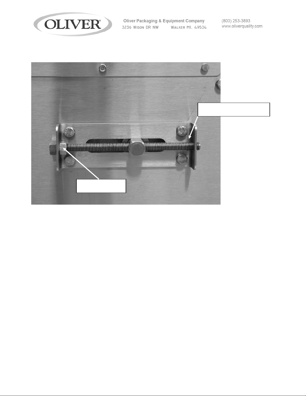
Conveyor Chain Tension Adjustment Mechanism
ADJUSTMENT SCREW
LOCKING NUT
1908S20074
1-9
Page 14

START-UP & OPERATION
To turn the machine on, plug in the power cord and wait 15 minutes to allow the heated
platen to reach operating temperature before attempting to seal trays.
Run the machine without trays and film to make sure everything is cycling properly.
1. VERIFY THE CONVEYOR IS READY TO OPERATE: Remove any extra items
that may have been placed on the conveyor and verify people are clear of the
trays and tray carriers. The guards (in-feed gate and clear exit cover) must be in
place and the emergency stop buttons must be in the up position (twist and allow
the button to pop up to reset).
2. VERIFY THE SEALING PLATEN IS CONNECTED TO THE PULL-DOWN
ARMS: Lift the black handles and hook the roller on the platen arch. This may be
left undone if it is desired to run the conveyor without operating the sealer.
3. PUSH THE GREEN “RUN” BUTTON.
4. PUSH THE RED “STOP” BUTTON TO STOP THE MACHINE WITH THE
SEALING PLATEN UP (NOT PRESSING ON A TRAY OR TRAY CARRIER).
NOTE: USE THE EMERGENCY-STOP BUTTONS OR THE SAFETY GATE
SWITCHES TO STOP THE MACHINE IN EMERGENCY SITUATIONS ONLY.
These switches act immediately and do not wait for the sealing cycle to finish.
This will leave the heater in contact with the tray resulting in over-heated
packaging materials. Stopping the machine improperly will result in a
shortened machine life.
5. TO CHANGE THE CONVEYOR SPEED: Adjust (turn) the black knob on the top
of the electrical box (lift the small stainless steel cover to access).
IMPORTANT NOTES
• Never run the machine with trays without film. Doing so can possibly cause a
jam because the trays can stick to the heated platen and be pulled out of the tray
carriers.
• Adjusting the speed of the conveyor will also change the dwell time of the sealer.
Excessively slow speeds will result in excessively sealed trays.
• If the conveyor becomes jammed, stop the conveyer and turn the power
off. The conveyor drive release knob may be pulled to allow manual movement
of the conveyor to aid removing jammed materials.
1908S20074
1-10
Page 15
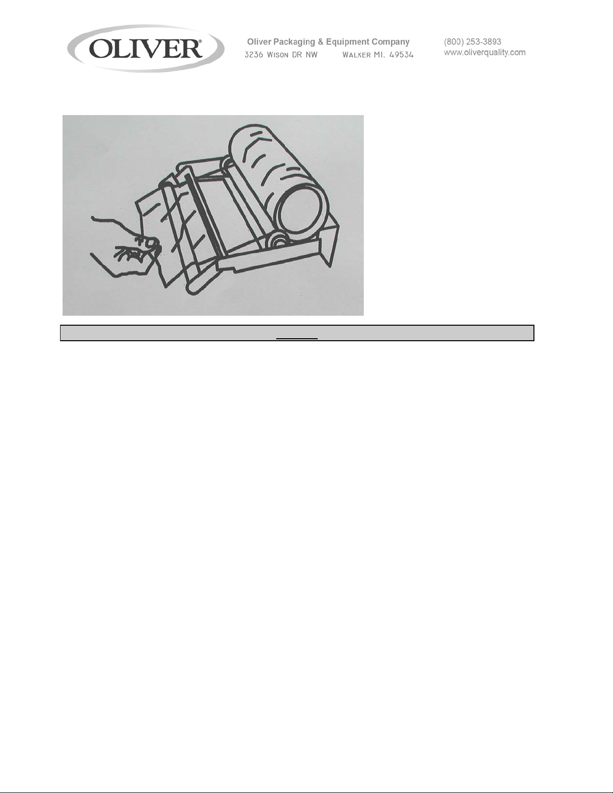
6. Load the film on the film stand as shown on the film-threading diagram located
on the machine and also shown in the diagram below.
NOTES
• The adhesive side of the film can be determined by pinching a fold and rubbing
the lid material against itself. Test both sides of the lid. The rough or tacky side
of the lid will be the adhesive side. The film supplied by Oliver is wound with the
adhesive side toward the inside of the roll. If the film is loaded in accordance
with the “FILM FEED” diagram it will be positioned properly for applying the
adhesive side of the film to the flange of the tray. If the film is loaded improperly,
it can cause the adhesive side to come in contact with the heated platen and the
film to stick to the heated platen. If this happens, the platen will need to be
cleaned.
• To thread the film through the machine, pull enough film off the roll so that you
can insert it into the slot between the tray carrier that is partially under the film
stand and the carrier that is upstream from that. After the film is hanging down
underneath the tray carrier, reach through the tray carrier and pull the film down
so that it touches the tray carriers underneath that are returning to come back up
on top. Then insert a tray into the tray carrier next to the film and cycle the
machine one time. This should seal the film to that tray and you can now fill the
rest of the conveyor with filled trays and begin running.
• The film dancer bar must move freely up and down.
• If you miss putting a tray in the machine it will not cause a problem, but the film
will be sealed to the top of the empty tray carrier. Let the machine continue to
run until that tray carrier goes around the bottom of the conveyor and comes
back up on top, then remove the piece of film.
1908S20074
1-11
Page 16

• It is important that the roll of film is centered on the conveyor. There are white
plastic film guides on either side of the film roll. These guides can be adjusted
from side-to-side by pushing them with your hand. If the film is not centered,
move both guides toward the side that the film needs to go to. It may take a little
bit of running time before you can tell if the film is in the correct position.
7. Place filled trays in tray carriers. Take care to avoid spilling food product on the
flange of the tray. Contamination of the flange can result in poor heat seals.
8. After a few trays come out of the machine, stop and inspect the acceptability of
the seals. If the seals are not acceptable or the trays do not come out of the
machine smoothly, refer to the trouble shooting guide.
9. The machine can be stopped at any time by pushing the stop button down.
When started again, the machine will pick up sealing where it left off.
NOTE
• IT IS NOT RECOMMENDED TO LEAVE THE MACHINE PLUGGED IN IF IT IS
GOING TO BE OUT OF OPERATION FOR AN EXTENDED PERIOD OF TIME.
1908S20074
1-12
Page 17

TECHNICAL SPECIFICATIONS
Model 1908
Tray Capacities: 6-3/8” (162mm) by 8.5” (216mm) maximum top-outside-dimensions of
the tray.
Temperature Range: Factory preset to approx. 300 degrees F.
Weight: 330 LBS.
Electrical: 120 VAC, 15 Amps, Single Phase, and 60 Hz
Air Requirements: 6 CFM @ 80 PSI
Machine Dimensions: 17” (43.2 cm) Wide x 64” (162.5 cm) Long x 45” (114.3 cm) High
1908S20074
1-13
Page 18

CLEANING AND MAINTENANCE
WARNING
Disconnect the power from the Model 1908 and allow the unit to cool before
performing cleaning and/or maintenance procedures.
These cleaning recommendations are not meant to replace or supersede plant-standard
manufacturing procedures or regulatory requirements. Do not immerse, hose down,
pressure wash, or otherwise soak electrical switches, electrical control box,
mechanical drive box, and electrical connections. Avoid getting these areas wet.
If your cleaning procedure involves liquid amounts greater than the use of a
damp cloth, protect these areas by shielding with plastic bags.
1. Heater Platen Cleaning:
CAUTION
• CAUTION HOT: The platen and surfaces around it may be very HOT! Care must
be taken to protect yourself and others. If the platen will be cleaned while it is still hot
make sure hand protection is used to prevent skin contact with the platen.
If food product comes in contact with the surface of the platen it tends to burn on and
become hard. This results in an irregular surface on the face of the platen that can
result in poor seals. If this happens, it will be necessary to remove this burnt on food
material.
1.1. Remove the In-feed guard.
1.2. Tip the film roll holder forward until it is resting on the side rails of the machine.
1.3. Remove the discharge cover and heat shield by removing the 4 black plastic
screw knobs on top of the covers and lift the covers off.
1.4. Release and tip the heater platen up by pulling the large black handles and
rotating the heater platen upwards until it is against the stops. The bottom of the
heater plate will be easily accessible.
1.5. Clean any food residue off the heater platen. When cleaning the surface of the
platen care must take to avoid scratching or gouging the surface. DO NOT
SCRAPE THE SURFACE OF THE PLATEN WITH SHARP OBJECTS AND
AVOID THE USE OF METAL TOOLS. Instead use a plastic or soft-metal
scouring pad such as Scotch Brite® or Chore Boy® brands provide a safe and
effective means of cleaning the heated platen. Wipe all surfaces with a
sanitizing agent after cleaning.
1908S20074
1-14
Page 19
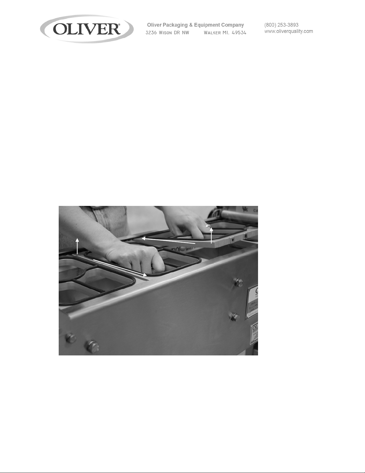
2. Tray Carrier Cleaning:
The tray carriers should be removed and cleaned daily. It is better to remove them
for cleaning rather than trying to clean them in the machine. The tray carriers can be
placed in your dishwasher for cleaning if you desire. Care should be taken so that
the rubber gaskets do not become damaged.
2.1. Disconnect the conveyor from the drive unit by lifting the cover on the side of the
machine and pulling the knob out. The knob will stay out if it is twisted ¼ turn
while pulling. This allows the conveyor to be moved manually.
The carriers should be removed in the middle of the in-feed area on the top of the
conveyor.
2.2. Lift up on two tray carriers next to each other and push one to one side while
pulling the other it to the other side. This spreads the chains so the pins can be
disengaged. Completely remove the two carriers as shown.
The picture below shows how to remove the tray carriers.
2.3. As the carriers are removed, the conveyor must be pulled forward to keep
getting to the remaining carriers. To move the conveyor forward, grasp a tray
carrier toward the infeed-end of the machine and pull the conveyor forward.
This must be done with the conveyor disconnected from the drive (step 2.1).
2.4. Wipe all surfaces with a sanitizing agent after cleaning.
2.5. Replace the tray carriers after cleaning the remainder of the machine.
1908S20074
1-15
Page 20

Note: Look for a white painted chain link to center on the side of the first tray
carrier re-installed to get the tray carrier/ chain timing correct.
Note: When replacing the tray carriers, it is extremely import to make sure that
all four pins on the conveyor chains are fully engaged in the holes of the tray
carrier. If the tray carriers are put in on an angle because the pins are not
engaged on one side, it could cause damage to the cutter assembly.
2.6. Re-engage the conveyor drive by twisting the release knob until it snaps in.
Move the conveyor manually until the pin locks in and prevents further
movement.
3. Clean the remainder of the machine:
3.1. Remove the two bottom pans by sliding them toward the discharge end of the
machine. Note: the pans may need to be jostled up and down slightly to get
them over bolt heads and other obstacles.
3.2. Clean the cutter assembly with a mild cleaner or sanitizing solution and a damp
cloth.
NOTE
The use of plastic or soft-metal scouring pads such as Scotch Brite® or Chore
Boy® brands provide a safe and effective means of cleaning the cutter assembly.
Wipe all surfaces with a sanitizing agent after cleaning.
3.3. Clean the pans and remaining surfaces of the machine with a mild cleaner or
and a damp cloth. Wipe all surfaces with a sanitizing agent after cleaning.
1908S20074
1-16
Page 21
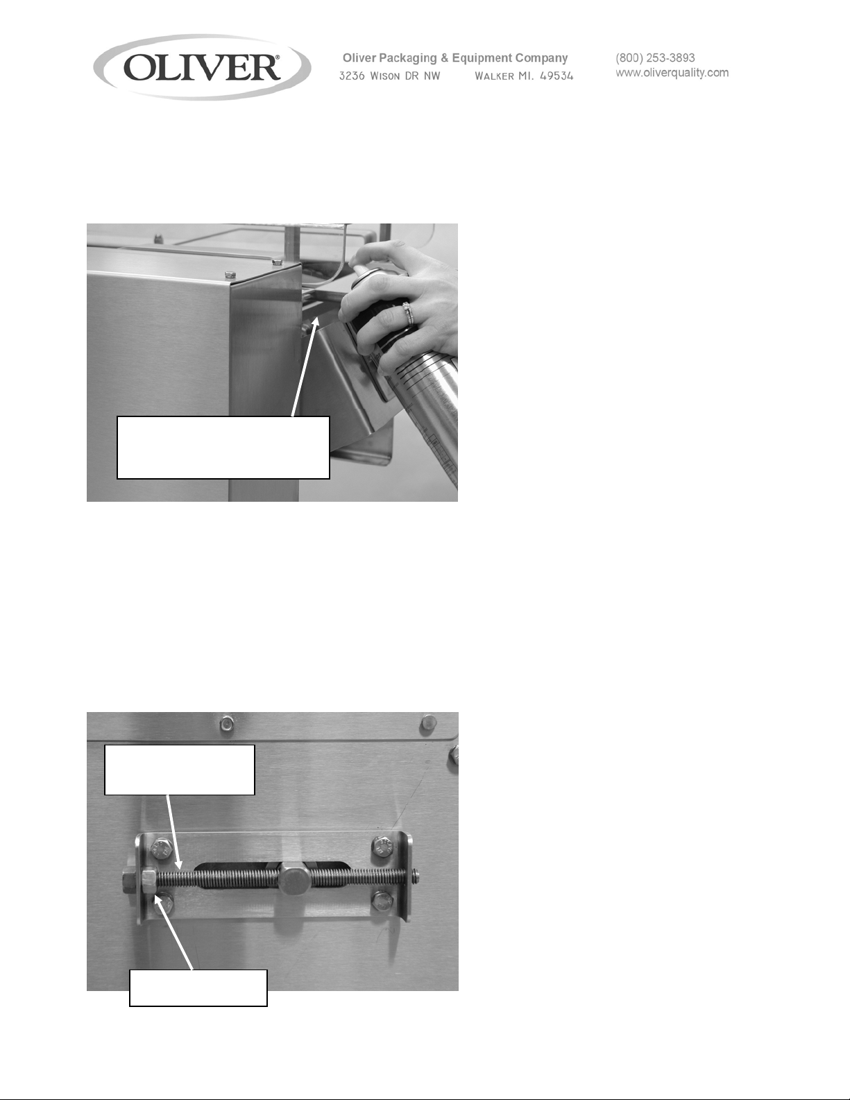
4. Conveyor Chain Maintenance
4.1. Once a month the conveyor chains should be lubricated with vegetable oil such
as cooking spray. If you use hose-down cleaning, this should be done twice a
month.
SPRAY CHAINS WHILE
MACHINE IS CYCLING
4.2. Once a month the conveyor chains should be checked for proper tension. The
tension can be checked by lifting the lower tray carriers at the middle of the
machine. If you can easily lift them up more than 3 inches, the chains are too
loose and should be tightened by adjusting the tensioners at the infeed-end of
the machine. Loosen the locking nuts and turn the adjusting screws clockwise
to tighten the chains then retighten the locking nut. It is important to adjust both
sides equally. The easiest way to do this is to count the turns that you tighten
one side and then do the same on the other side. The best method is to adjust
each side in ¼ turn increments and then recheck the chain tension.
ADJUSTING
SCREW
LOCKING NUT
1908S20074
1-17
Page 22

TROUBLESHOOTING
There are no user serviceable parts on your OLIVER Model 1908 Lidder except for the
cutter blade. Should you experience problems with your machine call the Oliver
Products Company 24 Hour Emergency Service number @ 1 800-253-3893.
Please have the serial number of your machine available to give to the Customer
Service representative.
Before calling for assistance please check the list below to see if the problem you are
experiencing is listed. If it is, try the corrective action items listed for that problem
before calling for assistance.
OPERATION ISSUES:
Symptom:
Machine does not power-up
(does not run and/or the
heater platen does not get
hot)
Machine receives power, but
the conveyor does not move
when the start button is
pushed.
Corrective Action:
1. Verify the machine is plugged in to a working
outlet.
2. If the platen does not heat, unplug the power
and remove and inspect the fuse (located in the
electrical panel, see section 4). Replace if
necessary (see parts list).
3. Verify the two e-stop buttons are not engaged
(pushed down). Twist the button to release it to
the ready to run position.
4. Verify the in-feed guard is installed in the correct
position (stainless steel gate hung in front of the
heater platen).
5. Verify the discharge cover is installed correctly
(plastic cover).
6. Verify the speed control knob is turned to 75% to
100% of the speed range.
1908S20074
1-18
Page 23

Conveyor does not move
when the start button is
pushed and steps 1-4
(above) have been taken.
A mechanical jam is
preventing the conveyor from
moving as indicated by a red
light in the electrical box
window.
7. Turn the speed up to 100%. Look in the window
of the electrical box under the conveyor outfeed. A green or red light should be visible.
--A green light indicates the motor is receiving power
and should be able to run. If only a green light is
visible, go to step 12.
--A red light indicates a mechanical jam— turn off the
main power immediately. Go to step 8.
--No light indicates power is not available to the motor
because a guard, e-stop switch, or main power switch
is tripped. Go to step 13.
8. Mechanically disconnect the indexer drive from
the conveyor by pulling the disconnect knob and
turning it 90 degrees (1/4 turn) so it stays out.
9. Mechanically disconnect the platen by pulling
the large black plastic handles. Allow the platen
springs to hold the platen up off the conveyor,
but do not remove guards and lift it as you
would for cleaning.
10. Manually pull the conveyor. If it pulls freely, the
problem is in the transmission box (Call for
service). If the conveyor does not move, look for
a jammed tray, an incorrectly installed and/or
wedged tray carrier, excessive food build-up,
excess film wrapped around a conveyor part or
the cutter, or excessive chain tension.
11. If no correctable cause is found for the jam, call
for service.
1908S20074
1-19
Page 24

The drive system appears to
be working correctly as
indicated by a green light in
the electrical box window,
but the conveyor does not
move.
12. Verify the drive is mechanically engaged with
the conveyor—Check the disconnect knob—
make certain it is not pulled out (twist the knob
and allow it to snap in). Give the conveyor a pull
until it “hooks up” (cannot be manually moved
further).
The drive system is not
receiving power as indicated
by the absence of lights
visible in the electrical box
window.
13. Recheck steps 1-6.
If step 13 does not remedy the problem, call for
service.
SEALING and TRAY BEHAVIOR ISSUES:
Poor seal quality
1. Verify that the platen is heated by placing your
hand near the platen and try to detect if there is
heat radiating out from it-DO NOT TOUCH THE
PLATEN
2. Check to see if the platen is dirty
3. Check rubber gasket on tray carriers for
damaged or missing pieces
4. Check to see that the film is centered on the tray
5. Check to see that the heat seal dwell is set
properly
6. Make sure that the tray flanges are not
contaminated with product
7. Verify the film is routed so the adhesive coated
side is oriented against the tray. See “Start-Up
and Operation” section step 6.
1908S20074
1-20
Page 25

Film does not cut
1. Inspect the cutter blade for wrapped filmYou must remove the cutter guard to do this
and if there is film wrapped around it the
film must be cut away and pulled off- THE
CUTTER BLADE IS SHARP, DO NOT
TOUCH-REMOVE ELECTRICAL POWER
PRIOR TO REMOVING GUARD.
2. Inspect to determine if the cutter blade is present.
3. Inspect to determine if the cutter blade is dull.
4. Inspect to determine if the cutter blade is dirty.
Film is not centered on tray Adjust the plastic guides on the film holder so that the
film is centered over the trays
Trays do not exit the machine
smoothly.
Adjust the position of the discharge table. Loosen the
thumb screws and move the table. Make the table
height slightly lower than the bottom of the trays as
they exit the conveyor. Keep the gap between the
table top and the conveyor small enough to prevent the
trays from tipping down between the conveyor and the
discharge table. (Reference the labeled photograph in
the “Machine Components” section of this document.)
Verify the film is being cut effectively, if not, see above.
1908S20074
1-21
Page 26
1908S20075
2-1
Page 27

This page intentionally left blank.
3- 1908S20076
1
Page 28
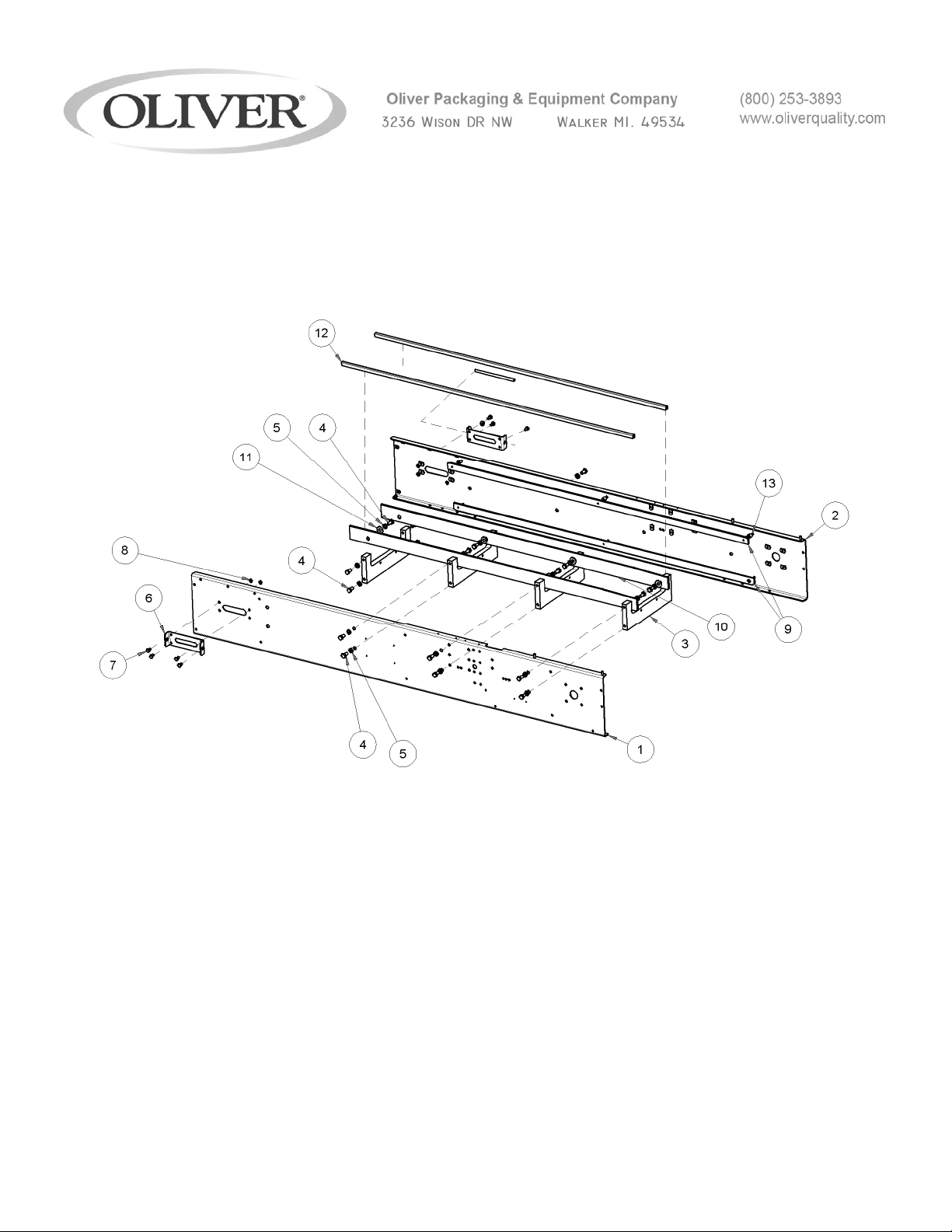
MECHANICAL REPLACEMENT PARTS LIST
EXPLODED VIEW (BASE FRAME)
3- 1908S20076
2
Page 29

MECHANICAL REPLACEMENT PARTS LIST
EXPLODED VIEW (BASE FRAME)
ITEM NO PART DESCRIPTION PART NUMBER QUANITY
1 FRAME FRONT 1908-0001 1
2 FRAME REAR 1908-0002 1
3 SPACER FRAME 1908-0003 4
4 SCREW HEX HD 3/8 -16 X 3/4 STST 5843-1052 24
5 WASHER 3/8 STST SPRING LOCK 5851-9359 24
6 TAKE UP – FRAME 1908-0054 2
7 SCREW HEX HD 1/4 – 20 X 1/2 STST 5843-1001 8
8 WASHER - 1/4 STST SPRING LOCK 5851-9357 8
9 SUPPORT CHAIN UPPER AND LOWER 1908-0007 4
10 STRIP CARRIER SUPPORT 1908-0024 2
11 WASHER – FLAT 3/8” 5851-9306 8
12 STRIP – WEAR 48.5” LONG 1908-0052 2
13 SPACER- CHAIN RAIL 1908-0010 12
3- 1908S20076
3
Page 30
For Service Parts Call 800-253-3893
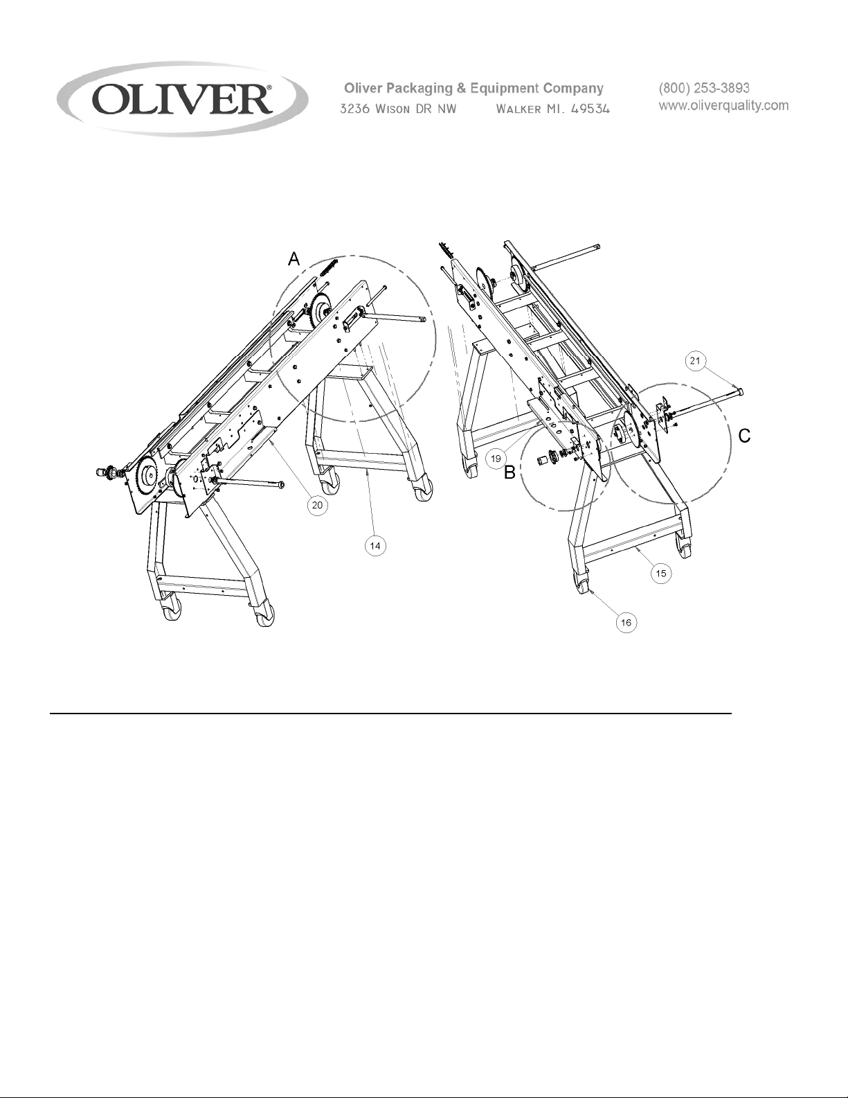
MECHANICAL REPLACEMENT PARTS LIST
EXPLODED VIEW (FRAME)
ITEM NO PART DESCRIPTION PART NUMBER QUANITY
14 LEGS, SENIOR MEALS 1908-0027 1
15 LEGS, SENIOR MEALS W/ HOLES 1908-0301 1
16 CASTER- STEM, 4” 5902-2409 4
17 SCREW, HEX HD 1/4-20 X 1 STST 5843-1005 8
18 NUT, HEX FULL 1/4-20 STST 5832-0520 8
19 SHELF, FRONT 1908-0300-0001 1
20 SHELF, REAR 1908-0300-0002 1
21 COLLAR- SET 3/4” I.D. STST 5806-7057 1
3- 1908S20076
For Service Parts Call 800-253-3893
4
Page 31
MECHANICAL REPLACEMENT PARTS LIST
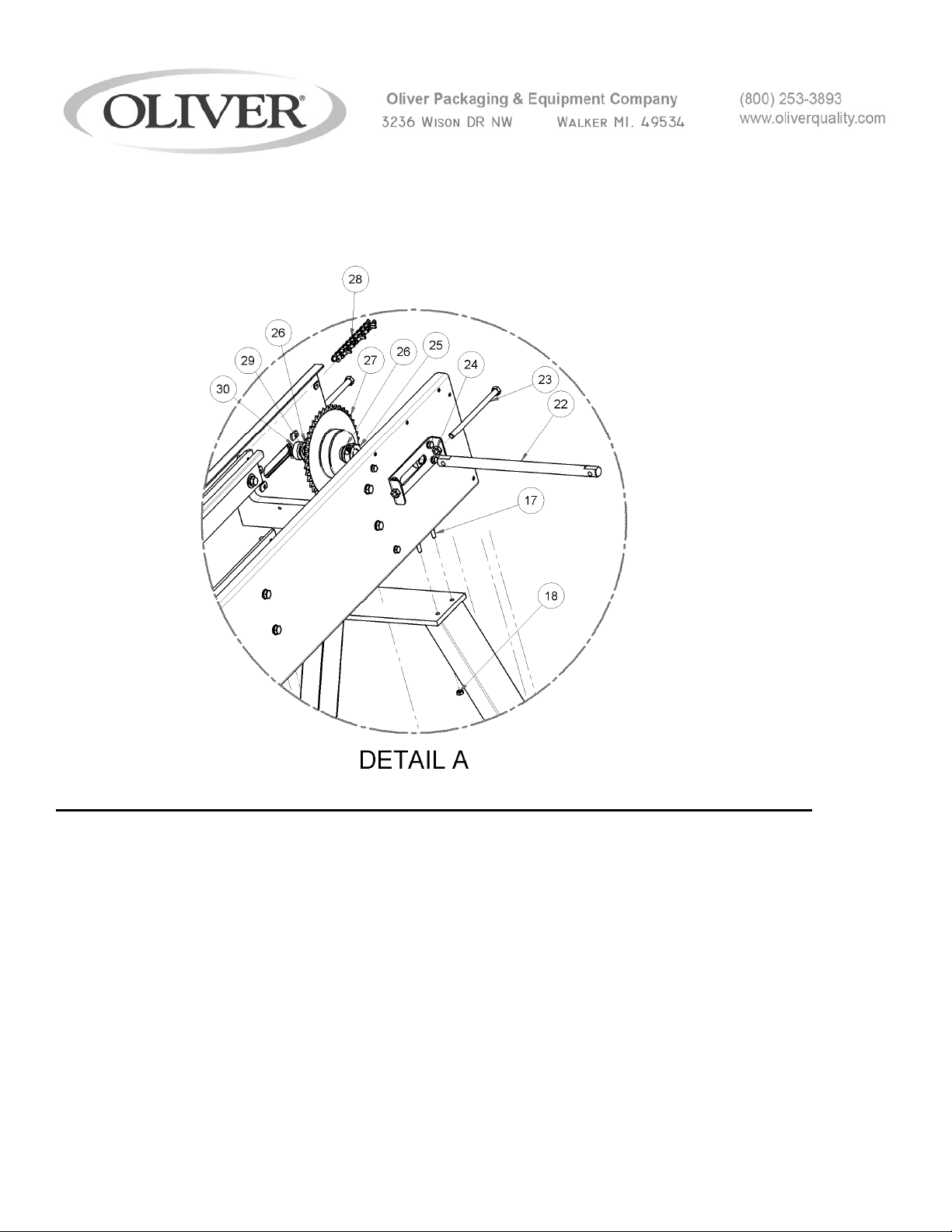
EXPLODED VIEW (FRAME)
ITEM NO PART DESCRIPTION PART NUMBER QUANITY
22 SHAFT, TAIL 1908-0006 1
23 SCREW, TAKE-UP 3/8-16 X 6 1/4 L. 1908-0005 2
24 NUT, HEX FULL 3/8-16 STST 5902-2409 2
25 COLLAR, SPLIT 3/4 BORE STST 5806-7115 2
26 BEARING, THRST 3/4 BORE 5254-0322 4
27 SPROCKET, 40B42, PLATED 5616-9349 2
28 CHAIN, MAIN (266 PITCHES) 5603-4928 2
29 BEARING, BRONZE SLEEVE 5254-0322 2
3- 1908S20076
5
Page 32
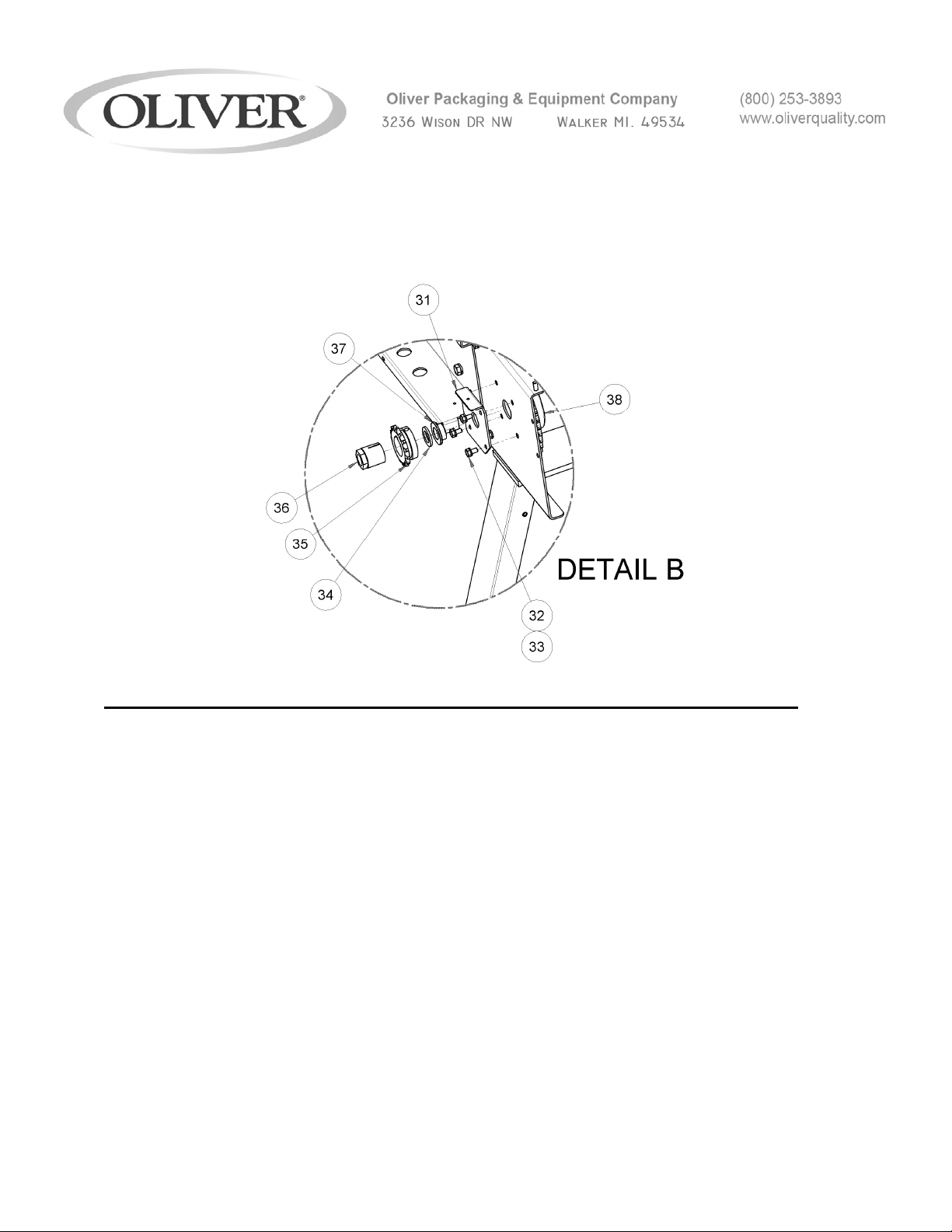
30 COLLAR, SET ¾ BORE 1908-0008 2
For Service Parts Call 800-253-3893
MECHANICAL REPLACEMENT PARTS LIST
EXPLODED VIEW (FRAME)
ITEM NO PART DESCRIPTION PART NUMBER QUANITY
31 BRACKET, FRONT BUSHING 1908-0302 1
32 SCREW, HEX HD 1/4-20 X 1/2 STST 5843-1001 8
33 WASHER, LOCK 1/4 STST 5851-9357 8
34 WASHER, SPACER 3/4 I.D. STST 1908-0305 2
35 SPROCKET, 40B15 1 ¼ FB” 5616-9076 1
36 BUSHING, EXPANDING 3/4 I.D. 5902-0220 1
37 BEARING, BRONZE FLANGED 5254-3032 2
38 SPROCKET, 40B42 ¾ FB PLATED 5616-9347 1
For Service Parts Call 800-253-3893
3- 1908S20076
6
Page 33
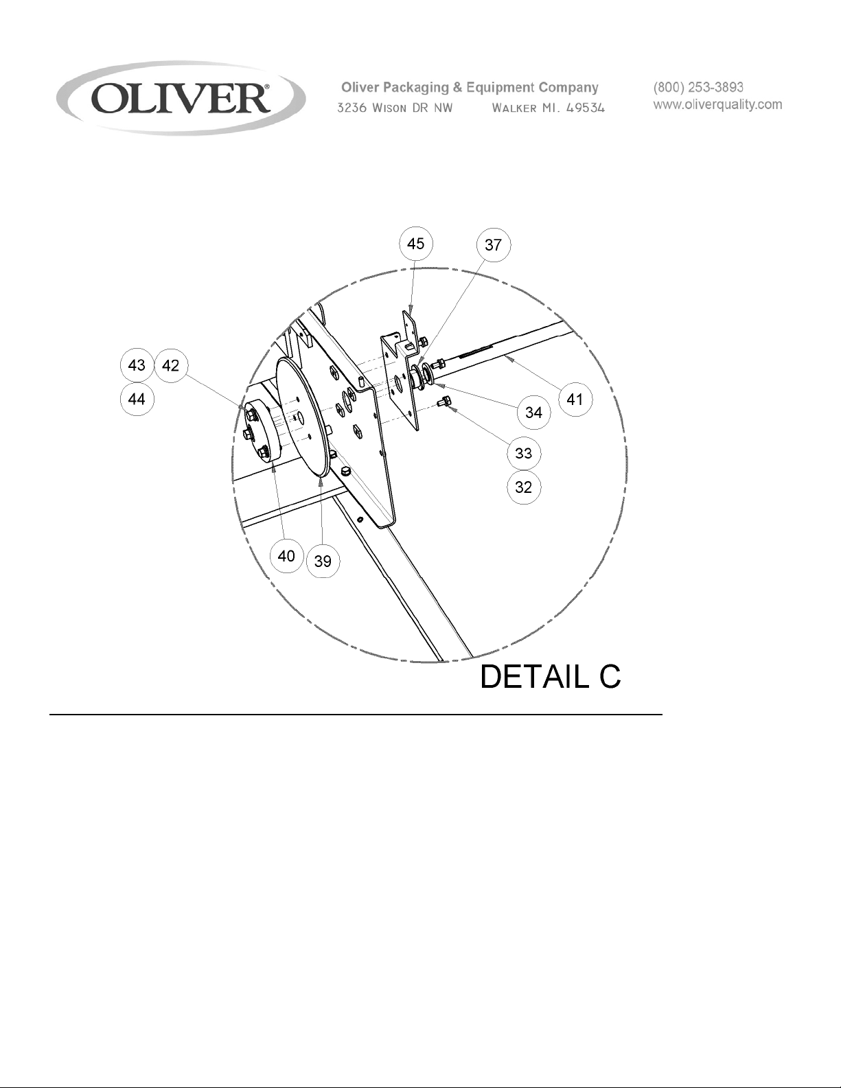
MECHANICAL REPLACEMENT PARTS LIST
EXPLODED VIEW (FRAME)
ITEM NO PART DESCRIPTION PART NUMBER QUANITY
39 SPROCKET, ADJUSTABLE 40A42 4615-4042-2431 1
40 RETAINER-HUB 1908-0053 1
41 SHAFT, CONVEYOR DRIVE 1908-0304 1
42 SCREW, HEX HD 5/16-18 X 1 STST 5843-1030 3
43 WASHER, LOCK 5/16 STST 5851-9358 3
44 WASHER, FLAT 5/16 STST 5851-9305 3
45 BRACKET, REAR BUSHING 1908-0303 1
46* KEY 3/16 SQ. X 1 STST. 5824-2319 2
3- 1908S20076
7
Page 34

For Service Parts Call 800-253-3893
3- 1908S20076
8
Page 35
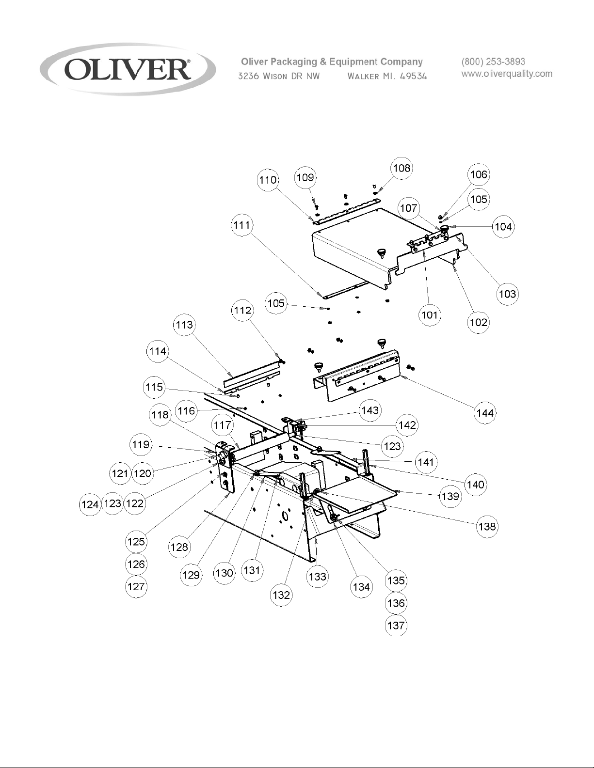
MECHANICAL REPLACEMENT PARTS LIST
EXPLODED VIEW (CUTTER DISCHARGE ASSEMBLY)
3- 1908S20076
9
Page 36

MECHANICAL REPLACEMENT PARTS LIST
EXPLODED VIEW (CUTTER DISCHARGE ASSEMBLY)
ITEM NO PART DESCRIPTION PART NUMBER QUANITY
101 HINGE, DISCHARGE FLAP 1908-0306 1
102 COVER, DISCHARGE 5500-5341 1
103 COVER, DISCHARGE FLAP 5500-5342 1
104 KNOB, 1” DIA KNURLED 1/4-20 5911-7024 1
105 WASHER, #10 LOCK STST 5851-9355 12
106 NUT, ACORN #10-24 5832-0585 6
107 SCREW, TRUSS HD #10-24 X ½ STST 5843-5385 6
108 WASHER, FLAT #10 STST 5851-9302 6
109 SCREW, HEX HD #10-24 X ½ STST 1908-0060 6
110 HINGE (SHOWING HALF) 1908-0060 .5
111 STRIP, HINGE BACKER 1808-0058 1
112 NUT, HEX #10-24 STST 5832-0578 6
113 BLADE, CUTTER 9 X 7/8 7107-7200 1
114 STRIP, BACKER 1908-0031 1
115 SCREW, SOC-SET 1/4-20 X 1/4” STST 5843-2031 4
116 SCREW, SOC-SET 1/4-20 X 3/8” STST 5843-2033 2
117 HOLDER, BLADE 7” CUT-OFF 1908-0030 1
118 SPROCKET, 40B14 ½ BORE 4617-4014-1631 1
119 RETAINER, FRONT BUSHING 1908-0066-1001 1
120 T-KNOB, CAP 5/16 S.H.C.S 5911-7076 2
121 SCREW, S.H.C.S. 5/16-18 X ½ STST. 5843-1551 2
3- 1908S20076
10
Page 37

For Service Parts Call Oliver Products @ 800-253-3893
MECHANICAL REPLACEMENT PARTS LIST
EXPLODED VIEW (CUTTER DISCHARGE ASSEMBLY)
ITEM NO PART DESCRIPTION PART NUMBER QUANITY
122 BEARING SINT BRNZ FLNG 5254-3110 2
123 SHAFT- BLADE HOLDER 1908-0029 2
124 SPRING PIN 5835-6572 2
125 SCREW- HEX HEAD 1/4-20 X 5/8 STST 5843-1002 4
126 WASHER- FLAT 1/4 STST 5851-9304 12
127 WASHER- LOCK 1/4 STST 5851-9357 12
128 BRACKET- SIDE, CUTTER R.H. 1908-0065-0001 1
129 NUT- ACORN 1/4 - 20 STST 5832-0590 2
130 BASE- TRAY LIFT GUIDE R.H. 1908-0089 1
131 LIFT- SENIOR MEAL TRAY 1908-0088 1
132 RETAINER, LIFT RAMP INSIDE 1908-0084 2
133 BRACKET, DISCHARGE MNT. 1908-0085 1
134 SUPPORT- SHELF 69042 1
135 NUT- WING 3/8-16 STST 5832-0597 2
136 WASHER-FLAT 3/8 STST 5851-9306 2
137 WASHER- LOCK 3/8 STST 5851-9359 2
138 SCREW, HEX HD 1/4-20 X 3/4 STST 5843-1003 2
139 ADJUSTABLE GUIDE SHELF 69043 1
140 SPACER, COVER 1908-0058-001 2
141 BASE- TRAY LIFT GUIDE L.H. 1908-0090 1
142 BRACKET- SIDE, CUTTER L.H. 1908-0065-0002 1
143 RETAINER, REAR BUSHING 1908-0066-1002 1
144 COVER- CUTTER 1908-0032-001 1
145* NUT 1/4-20 WING STST 5832-0595 2
3- 1908S20076
11
Page 38

For Service Parts Call Oliver Products @ 800-253-3893
3- 1908S20076
12
Page 39

This page intentionally left blank.
3- 1908S20076
13
Page 40
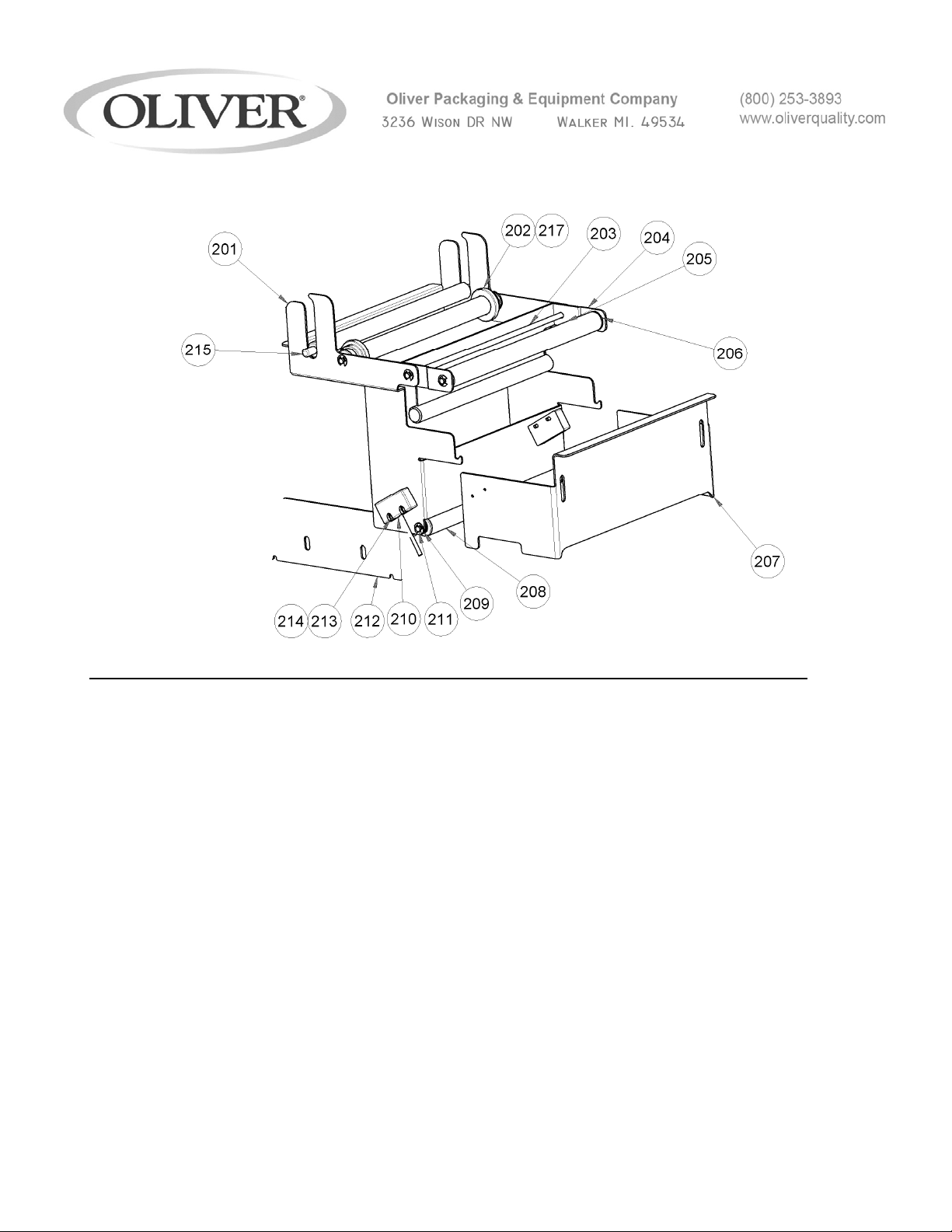
MECHANICAL REPLACEMENT PARTS LIST
EXPLODED VIEW (TOP ASSEMBLY, GUARD, ROLL HOLDER)
ITEM NO PART DESCRIPTION PART NUMBER QUANITY
201 GUARD/ ROLL HOLDER WELDMENT 1908-0308 1
202 ROLLER FILM GUIDE 1908-0041 2
203 ROD-FILM DISPENSER 11 1/4 L 1908-0043 3
204 BRACKET FILM TAKEUP 1908-0163 1
205 TUBE, ALUMINUM 7/8 O.D. X 10 1/2 L 4639-1414-1114 2
206 BEARING, ROLL END 5252-3002 6
207 GUARD, INFEED GATE 1908-0309 1
208 TUBE, ALUMINUM 7/8 O.D. X 9 1/4 L 4639-1414-1114 1
209 RING, RETAINING 1/4 5840-1273 8
210 SAFETY SWITCH (W/ CONNECTOR) 1908-0416 1
211 ROD-FILM DISPENSER 10 1/4 L 1908-0040 1
212 BRACKET, PLATEN GUARD (REAR) 1908-0307-0001 1
213 SCREW, RND HD #6-32 X 1/2 STST 5843-5212 4
3- 1908S20076
14
Page 41

For Service Parts Call 800-253-3893
3- 1908S20076
15
Page 42

ITEM NO PART DESCRIPTION PART NUMBER QUANITY
214 WASHER, LOCK #6 STST 5851-9353 4
215 ROLLER- FILM WEIGHT 1908-0310 1
216* BRACKET, PLATEN GUARD (FRONT) 1908-0307-0001 1
217* “O” RING 13/16 I.D. X 1 1/16 O.D. 6909-3211 2
3- 1908S20076
16
Page 43
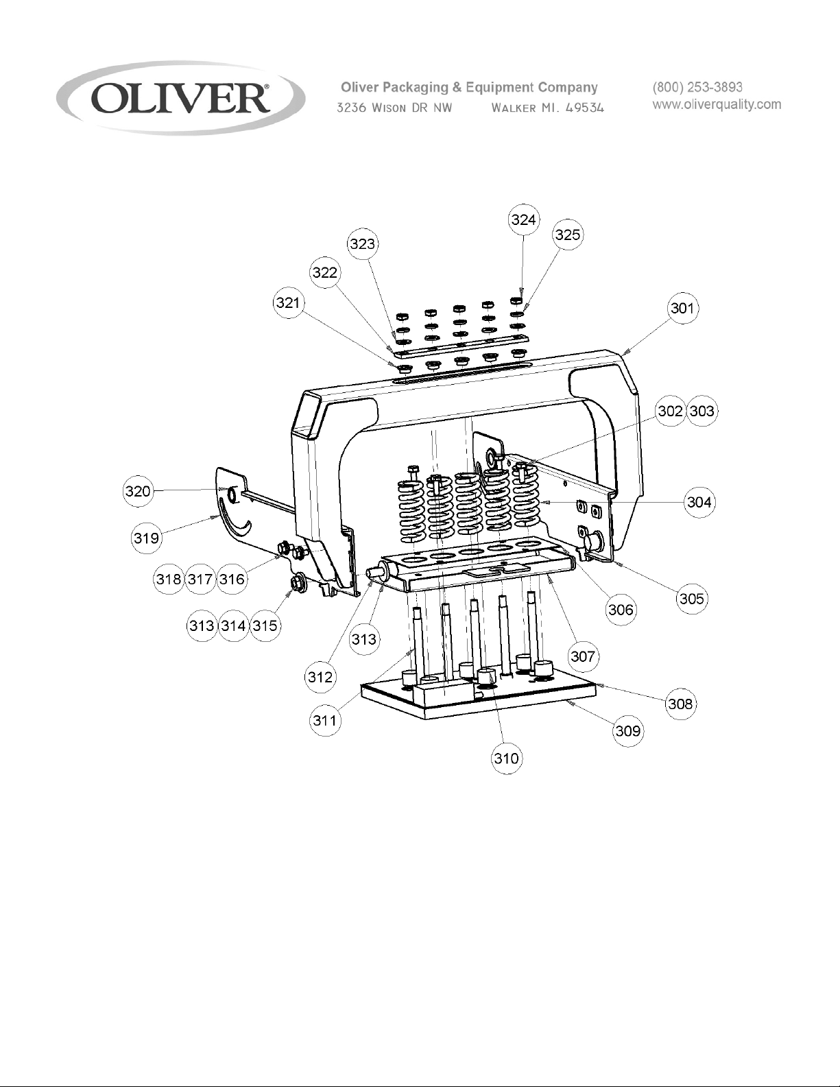
MECHANICAL REPLACEMENT PARTS LIST
EXPLODED VIEW (ARCH-PLATEN ASSEMBLY)
For Service Parts Call 800-253-3893
3- 1908S20076
17
Page 44

MECHANICAL REPLACEMENT PARTS LIST
EXPLODED VIEW (ARCH-PLATEN ASSEMBLY)
ITEM NO PART DESCRIPTION PART NUMBER QUANITY
301 ARCH WELDMENT ASSY 1908-0311 1
302 SCREW, HEX HD 1/4-20 X 3/4 STST 5843-1003 4
303 WASHER, LOCK INT. TOOTH ¼ STST 5851-9395 1
304 SPRING, COMPRESSION 7014-4400 5
305 ARM, FRONT PIVOT 1908-0317 1
306 PLATE, PLATEN SPRING 1908-0313 1
307 PAN, PLATEN SPRING 1908-0312 1
308 PLATE, HEATER COVER 1908-0316 1
309 HEATER PLATEN ASSY 1908-25607 1
310 CYLINDER, HEATER STANDOFF 1908-0315 6
311 SCREW, SHLDR 3/8 X 3 1/2 STST 5842-8999 5
312 BEARING, CAM FOLLOWER 3/4 DIA 5251-0021 2
313 WASHER, SPACER, 3/8 I.D 1908-0319 6
314 WASHER, LOCK 3/8 STST 5851-9359 2
315 NUT – HEX JAM 3/8-24 STST 5832-0552 2
316 SCREW, HEX HD 1/4-20 X 1/2 STST 5843-1001 6
317 WASHER, LOCK 1/4 STST 5851-9357 6
318 WASHER, FLAT 1/4 STST 5851-9305 6
319 ARM, REAR PIVOT 1908-0318 1
320 BEARING, SINT. BRNZ. FL. 1/2 I.D. 5254-3110 2
321 BEARING, SINT. BRNZ. FL. 3/8 I.D. 5254-3085 5
322 BAR, BOLT SPACER 1908-0314 1
323 WASHER-FLAT 5/16” STST 5851-9305 5
324 NUT, HEX 5/16-18 STST 5832-0521 5
325 WASHER, LOCK 5/16 STST 5851-9358 5
3- 1908S20076
18
Page 45

This page intentionally left blank.
For Service Parts Call 800-253-3893
3- 1908S20076
19
Page 46
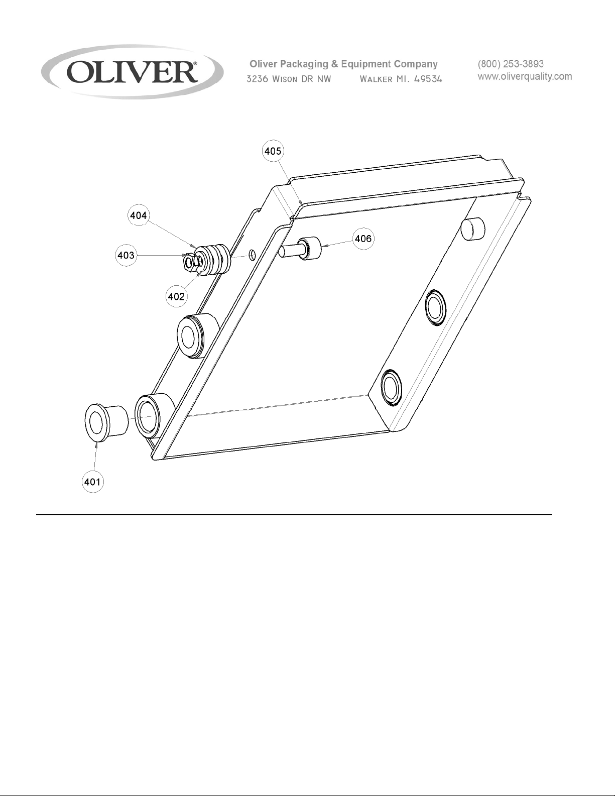
MECHANICAL REPLACEMENT PARTS LIST
EXPLODED VIEW (DRIVE BOX ASSEMBLY (ROCKER))
ITEM NO PART DESCRIPTION PART NUMBER QUANITY
401 BEARING, SINT BRONZE 3/4 I.D. 5254-3139 8
402 WASHER, LOCK 3/8 STST 5851-9359 2
403 NUT – HEX JAM 3/8-24 STST 5832-0552 2
404 WASHER, SPACER, 3/8 I.D 1908-0319 6
405 WELDMENT, ROCKER FRAME 1908-0326 1
406 BEARING, CAM FOLLOWER 3/4 DIA 5251-0021 2
For Service Parts Call 800-253-3893
3- 1908S20076
20
Page 47
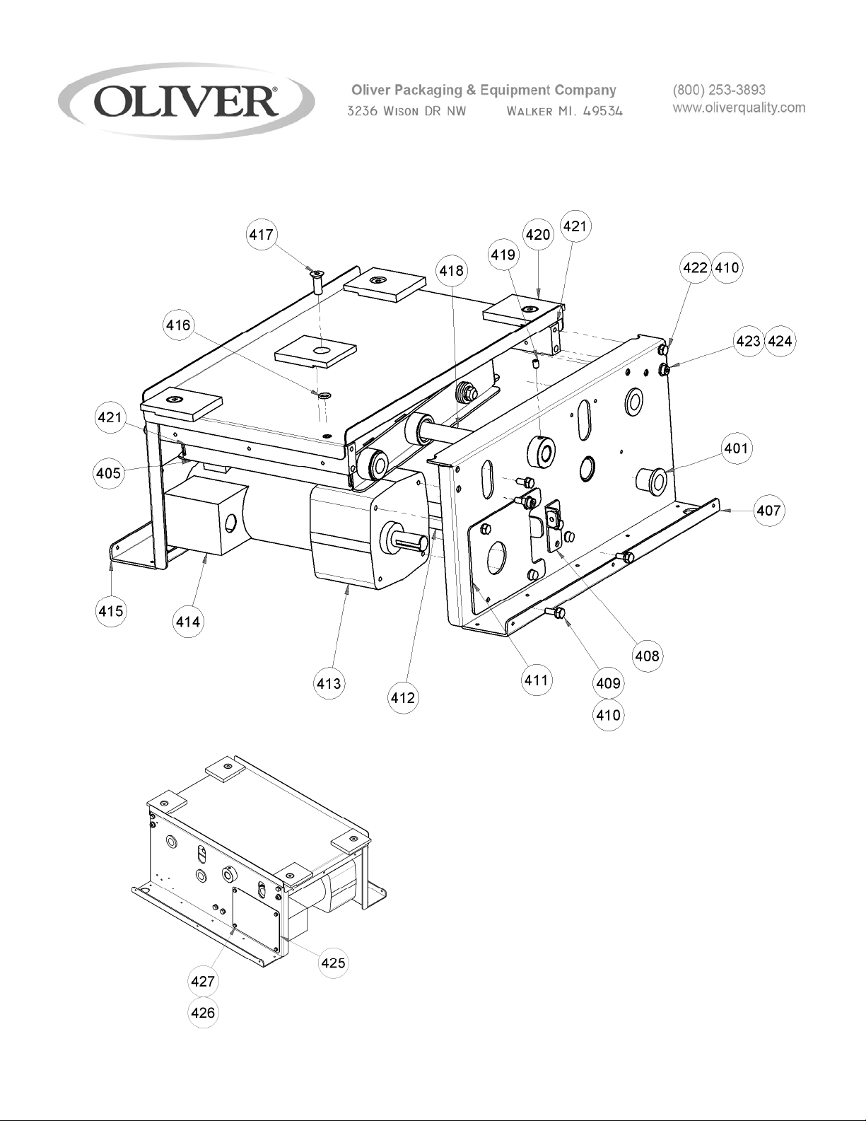
MECHANICAL REPLACEMENT PARTS LIST
EXPLODED VIEW (DRIVE BOX ASSEMBLY (BASE ))
For Service Parts Call 800-253-3893
3- 1908S20076
21
Page 48

MECHANICAL REPLACEMENT PARTS LIST
EXPLODED VIEW (DRIVE BOX ASSEMBLY (BASE ))
ITEM NO PART DESCRIPTION PART NUMBER QUANITY
407 WELDMENT, FRONT PANEL 1908-0320-0001 1
408 BRACKET, CHAIN ADJUSTER 1908-0323 1
409 SCREW, HEX HD 1/4 -28 X 3/4 STST 5843-1253 4
410 WASHER, LOCK 1/4 STST 5851-9357 13
411 PLATE, MOTOR MOUNT 1908-0321 1
412 BAR- BOTTOM TIE 1908-0322 1
413 GEARMOTOR, DC 6310-0203 1
414 BOX, GEARMOTOR CONDUIT 6310-4000 1
415 WELDMENT, REAR PANEL 1908-0320-0002 1
416 “O” RING, 3/8 I.D. 6909-3110 4
417 SCREW, FLAT SOC HD 3/8-16 X 1 STST 5843-2745 4
418 SHAFT, ROCKER 1908-0327 1
419 SCREW, SOC SET 1/4-20 X 3/8 5843-2033 2
420 BLOCK, MOUNTING CLAMP 1908-0329 4
421 BAR- TOP TIE 1908-0324 2
422 SCREW, HEX HD 1/4-20 X 5/8 5843-1002 9
423 SCREW – SHOULDER 5/16 X 3/8 5842-8958 4
424 WASHER-LOCK 5/15 STST 5851-9358 4
425 PLATE, MOTOR COVER 1908-0328 1
426 SCREW, HEX HD #10-24 X 3/8 STST 5843-1231 4
427 WASHER, LOCK #10 STST 5851-9355 4
428 TOP PANEL 1908-0325 1
3- 1908S20076
22
Page 49

For Service Parts Call 800-253-3893
3- 1908S20076
23
Page 50

This page intentionally left blank.
3- 1908S20076
24
Page 51
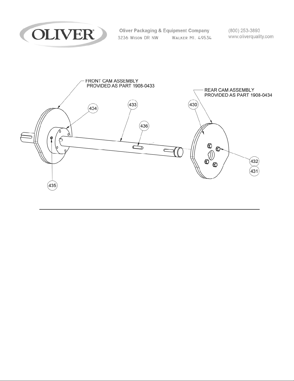
MECHANICAL REPLACEMENT PARTS LIST
EXPLODED VIEW (DRIVE BOX ASSEMBLY (PLATEN CAM ))
REV 1/6/12
ITEM NO PART DESCRIPTION PART NUMBER QUANITY
430 PLATE, PLATEN CAM 1908-0341 4
431 SCREW, HEX HD #10-24 X 3/4 STST 5843-1234 8
432 WASHER, LOCK #10 STST 5851-9355 16
433 SHAFT, DRIVE INPUT 1908-0336 1
434 HUB, PLATEN CAM 1908-0340 2
435 SCREW, SOCKET SET 1/4-20 X 3/8 5842-6133 7
436 KEY, 3/16 SQ. X 3/4 5824-2318 7
3- 1908S20076
25
Page 52

For Service Parts Call 800-253-3893
3- 1908S20076
26
Page 53
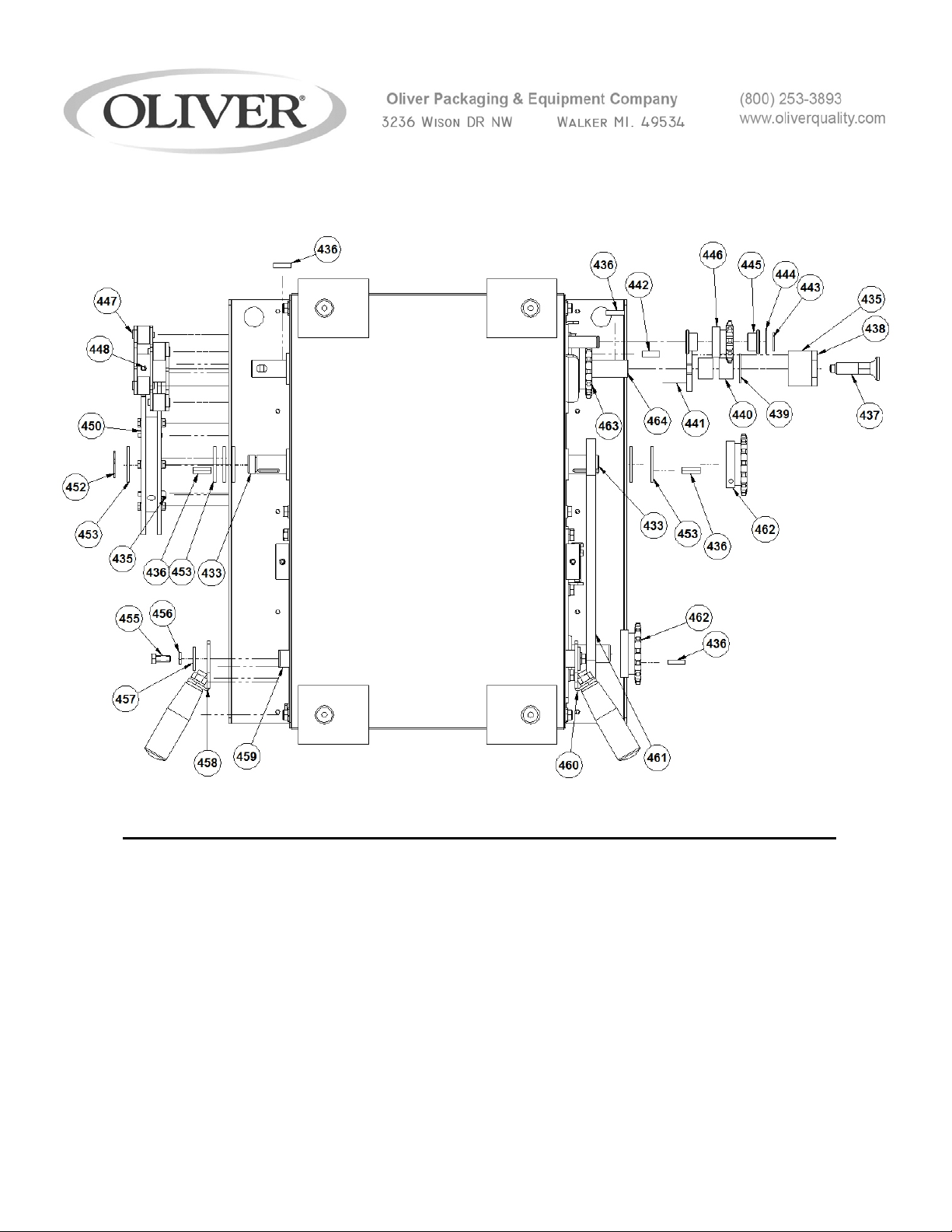
MECHANICAL REPLACEMENT PARTS LIST
EXPLODED VIEW (DRIVE BOX ASSEMBLY (EXTERIOR))
ITEM NO PART DESCRIPTION PART NUMBER QUANITY
437 PIN, LOCKING MANUAL PULL 5835-7930 1
438 CONVEYOR DRIVE LOCK BLOCK 1908-0335 1
439 BEARING, SINT. BRNZ THRUST 3/4 I.D. 5254-3514 1
440 BEARING, SINT. BRNZ SLEEVE 3/4 I.D. 5254-0300 2
441 HUB, CONVEYOR DRIVE 1908-0334 1
442 KEY, 1/4 SQ. X 3/4 5824-2324 1
443 RING, RETAINING E-CLIP STST 1/2 I.D. 5840-2839 1
444 WASHER-SPACER 1/2 I.D. X 16 GA. 1908-0331 1
445 BEARING, SINT. BRNZ FL 1/2 I.D. 5254-3110 2
3- 1908S20076
27
Page 54

For Service Parts Call 800-253-3893
3- 1908S20076
28
Page 55

MECHANICAL REPLACEMENT PARTS LIST
EXPLODED VIEW (DRIVE BOX ASSEMBLY (EXTERIOR))
ITEM NO PART DESCRIPTION PART NUMBER QUANITY
446 SPROCKET, #40 10 TOOTH 3/4 BORE 5616-9023 1
447 INDEXER ROLLER ASSEMBLY 1908-0333 1
448 SCREW, SOCKET SET 1/4-20 X 1/4 5842-6131 2
450 INDEXER CAM ASSEMBLY 1908-0359 1
452 RING, RETAINING E-CLIP STST 3/4 I.D. 5840-2841 1
453 WASHER-SPACER KEYED 3/4 I.D. 1908-0339 6
455 SCREW-HEX HD, 1/4-20 X 5/8 STST 5843-1002 2
456 WASHER, LOCK 1/4 STST 5851-9357 3
457 WASHER, PULL DOWN 1908-0344 2
458 LINK, PLATEN PULL DOWN, REAR 1908-0343-0002 1
459 SHAFT, PULL DOWN 1908-0342 1
460 LINK, PLATEN PULL DOWN, FRONT 1908-0343-0001 1
461 CHAIN, #40 ROLLER 5603-4003 2 FT.
462 SPROCKET, #40 15 TOOTH 3/4 BORE 5616-9073 2
463 SPROCKET, #40 15 TOOTH 1 1/4 BORE 5616-9076 1
464 SHAFT, CONVEYOR DRIVE OUTPUT 1908-0332 1
For Service Parts Call 800-253-3893
3- 1908S20076
29
Page 56
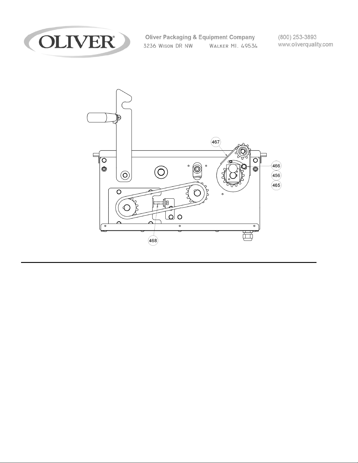
MECHANICAL REPLACEMENT PARTS LIST
EXPLODED VIEW (DRIVE BOX ASSEMBLY (EXTERIOR))
ITEM NO PART DESCRIPTION PART NUMBER QUANITY
465 SCREW, HEX HD 1/4-20 X 1/2 STST 5843-1001 1
466 WASHER-FLAT 1/4 STST 5851-9304 1
467 WELDMENT, IDLER BRACKET 1908-0330 1
468 SCREW, HEX HD 1/4-20 X 1 1/2 STST 5843-1007 1
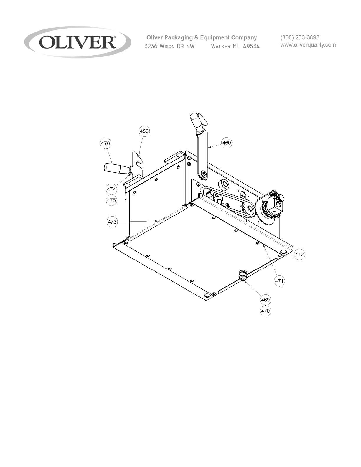
469 STRAIN RELIEF, 1/2 NPT 5765-1082 1
470 NUT, 1/2 NPT LOCK 5766-7750 1
471 PANEL, BOTTOM 1908-0345 1
472 SCREW, TRUSS HD #10-24 X 3/8 STST 5843-5384 16
473 PANEL, END 1908-0347 2
474 NUT, HEX 3/8-16 STST 5832-0522 2
475 WASHER, LOCK 3/8 STST 5851-9359 2
476 HANDLE, 1” DIA X 3” 3/8-16 STUD 5908-5058 2
3- 1908S20076
30
Page 57
For Service Parts Call 800-253-3893
MECHANICAL REPLACEMENT PARTS LIST
EXPLODED VIEW (DRIVE BOX ASSEMBLY (EXTERIOR))
3- 1908S20076
31
Page 58
For Service Parts Call 800-253-3893
MECHANICAL REPLACEMENT PARTS LIST
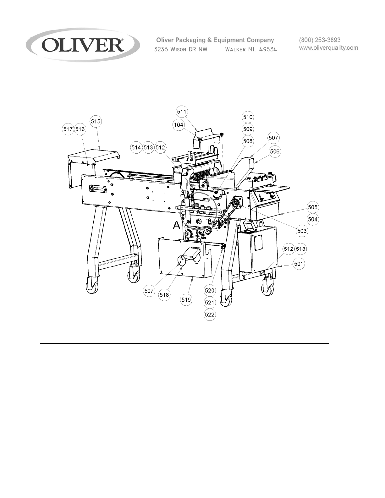
EXPLODED VIEW (MAIN ASSEMBLY)
ITEM NO PART DESCRIPTION PART NUMBER QUANITY
501 ELECTRICAL BOX ASSEMBLY 1908-25611 1
503 CHAIN, #40 ROLLER 5603-4003 3 FT.
504 PAN, INFEED BOTTOM 1908-0411 1
505 PAN, OUTFEED BOTTOM 1908-0412 1
506 GUARD, FRONT CHAIN 1908-0407 1
507 SCREW, TRUSS HD #10-24 X 3/8 STST 5843-5384 17
508 SCREW, SHOULDER ½ DIA X ½ L STST 5842-8996 2
509 WASHER-LOCK, 3/8 STST 5851-9359 2
510 NUT, HEX 3/8-16 STST 5832-0522 2
3- 1908S20076
32
Page 59

For Service Parts Call 800-253-3893
3- 1908S20076
33
Page 60
MECHANICAL REPLACEMENT PARTS LIST
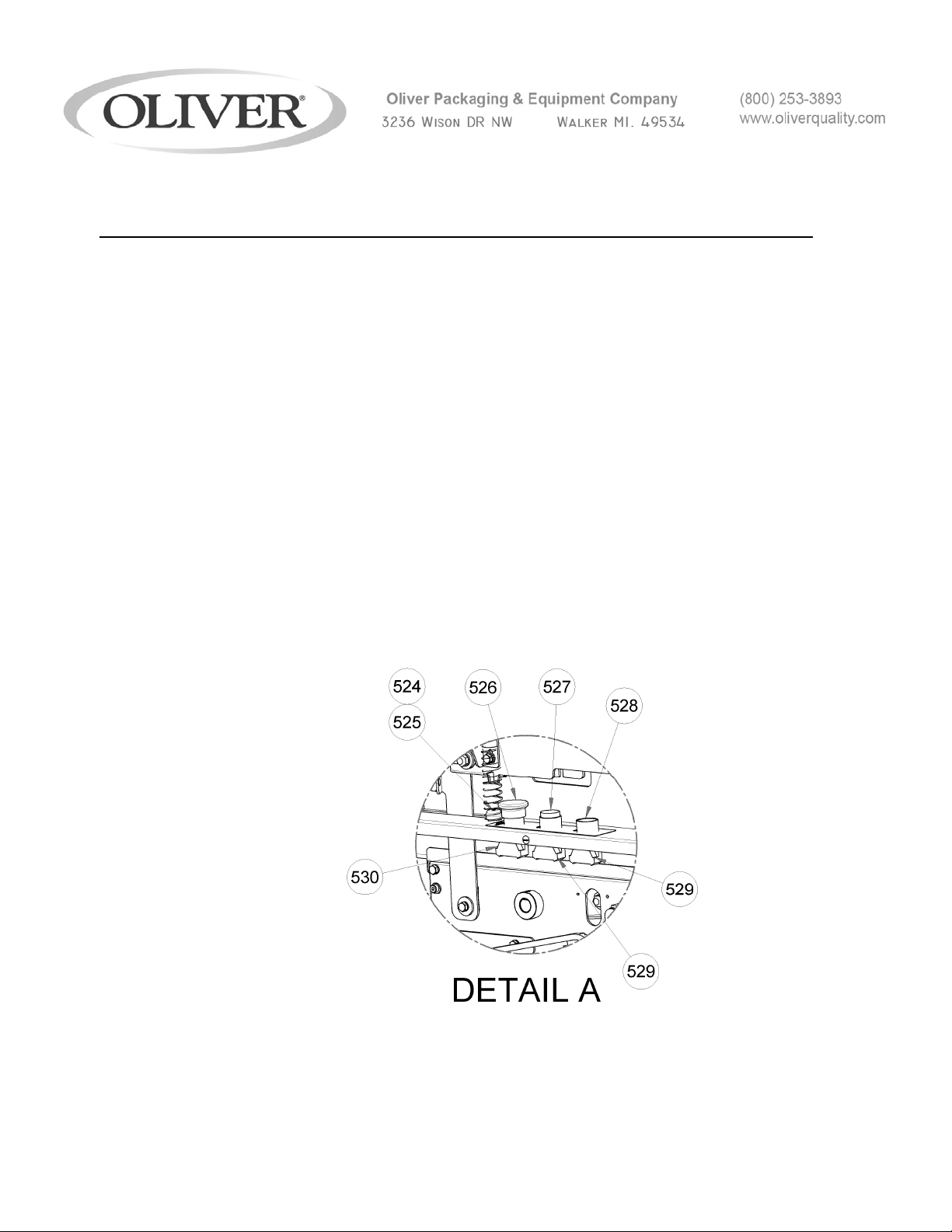
EXPLODED VIEW (MAIN ASSEMBLY)
ITEM NO PART DESCRIPTION PART NUMBER QUANITY
511 COVER, PLATEN BACK 1908- 0410 1
512 SCREW, HEX HD 1/4-20 X 1/2 STST 5843-1001 8
513 WASHER, LOCK 1/4 STST 5851-9357 8
514 WASHER, FLAT 1/4 STST 5851-9304 4
515 GUARD, INFEED 1908-0021 1
516 SCREW, HEX HD #10-24 X 3/8 STST 5843-1231 10
517 WASHER, LOCK #10 STST 5851-9355 10
518 SHEILD, SHAFT LOCK 1908-0405 1
519 WELDMENT, FRONT COVER 1908-0406 1
520 STRAIN RELIEF, 1/2 NPT 5765-1082 2
521 NUT, 1/2 NPT LOCK 5766-7750 2
522 CONTROL CABLE ASSEMBLY, FRONT 1908-0402 1
524 BUTTON, SPRING MOUNT 1908-0404 2
3
525 SPRING, COMPRESSION 7015-5100 2
526 PUSH BUTTON, MUSHROOM RED 5708-7920 2
3- 1908S20076
34
Page 61
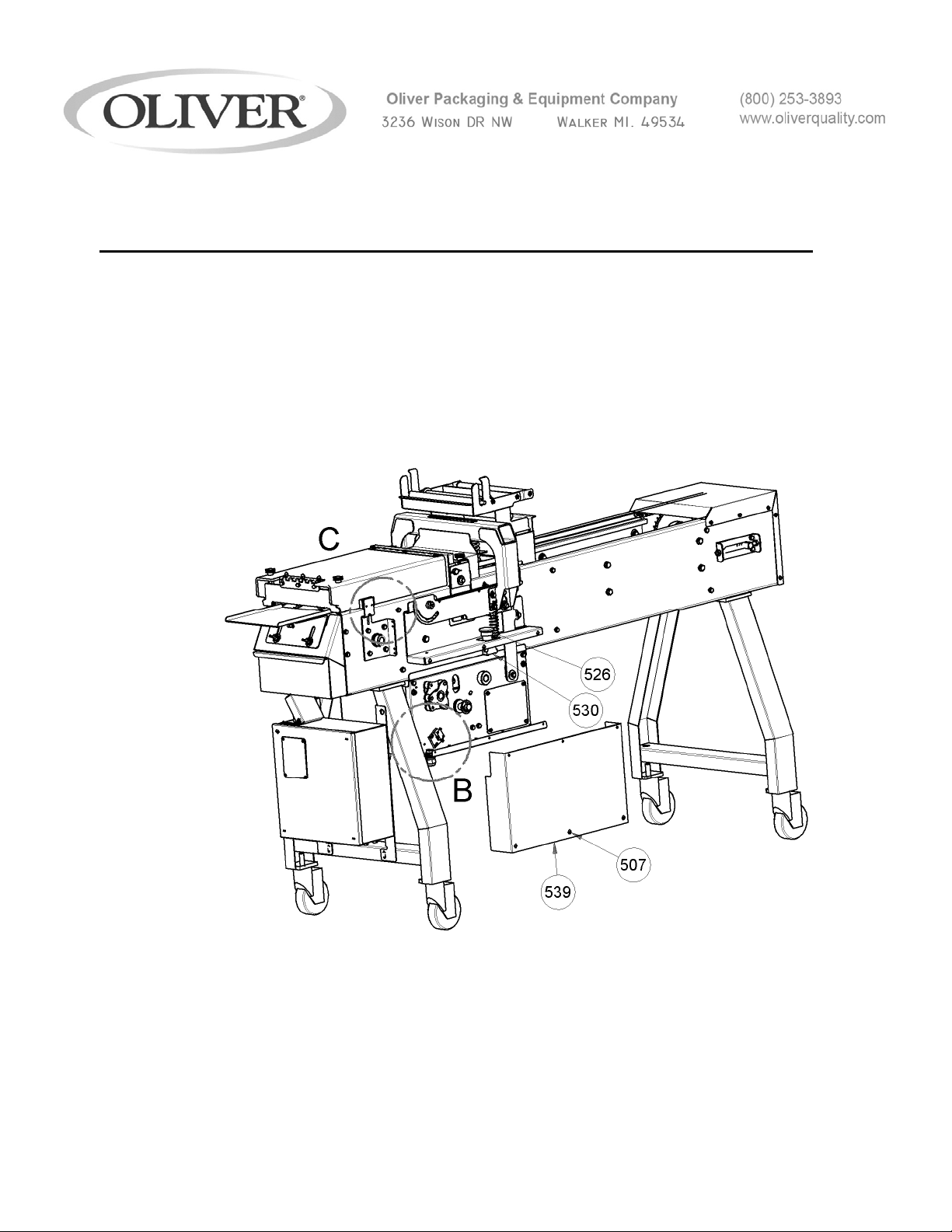
For Service Parts Call 800-253-3893
MECHANICAL REPLACEMENT PARTS LIST
EXPLODED VIEW (MAIN ASSEMBLY)
ITEM NO PART DESCRIPTION PART NUMBER QUANITY
527 PUSH BUTTON, EXTENDED RED 5708-7908 1
528 PUSH BUTTON, FLUSH GREEN 5708-7900 1
529 CONTACT BLOCK, NO 5708-7930 2
530 CONTACT BLOCK, NC 5708-7931 2
3- 1908S20076
35
Page 62

For Service Parts Call 800-253-3893
3- 1908S20076
36
Page 63
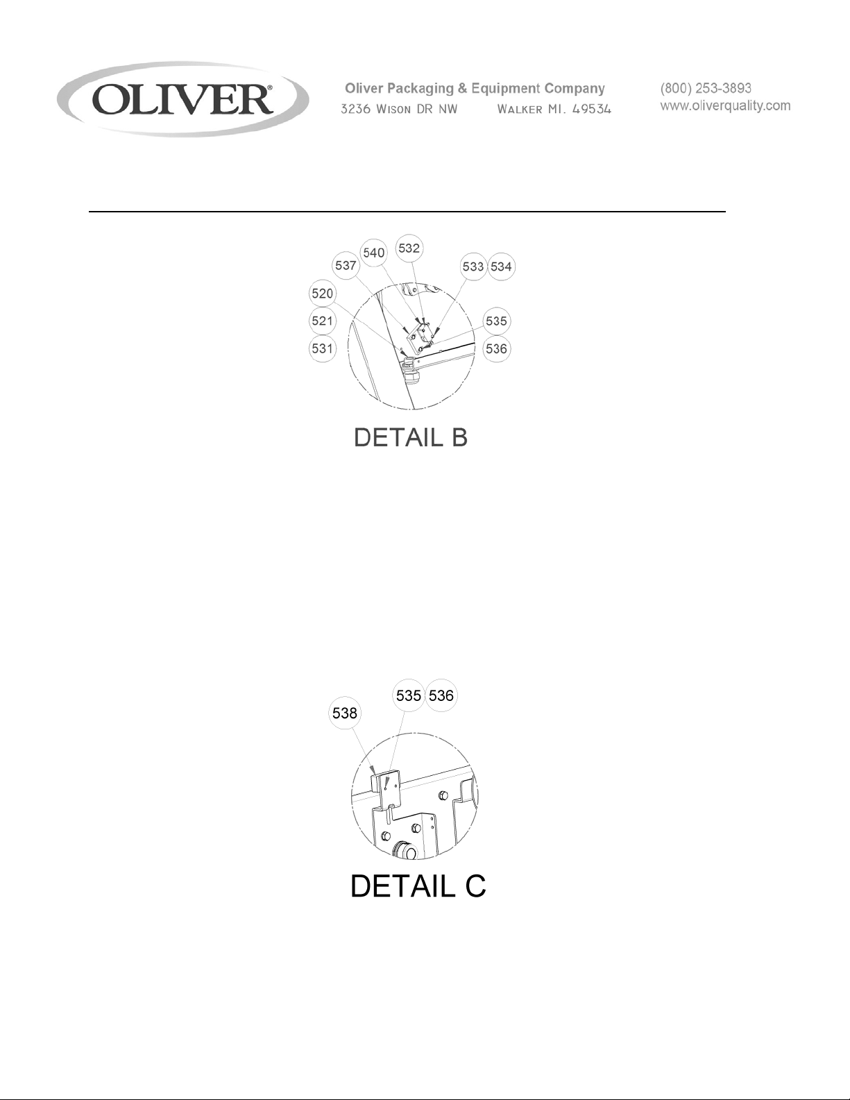
MECHANICAL REPLACEMENT PARTS LIST
EXPLODED VIEW (MAIN ASSEMBLY)
ITEM NO PART DESCRIPTION PART NUMBER QUANITY
531 CONTROL CABLE ASSEMBLY, REAR 1908-0403 1
532 SWITCH, LIMIT W/ ROLLER 5757-8002 1
533 SCREW, RND HEAD #4-40 X 3/4 5843-5193 2
534 WASHER, LOCK #4 STST 5851-9352 2
535 SCREW, RND HEAD #6-32 X 1/2 STST 5843-5212 2
536 WASHER, LOCK SHKPRF #6 STST 5851-9219 2
537 BLOCK, LIMIT SWITCH SPACER 1908-0408 1
538 SAFETY SWITCH W/ CONNECTOR 1908-0416 1
539 REAR COVER 1908-0409 1
540 SHIM, LIMIT SWITCH MNT 1908-0417 1
3- 1908S20076
37
Page 64

For Service Parts Call 800-253-3893
3- 1908S20076
38
Page 65
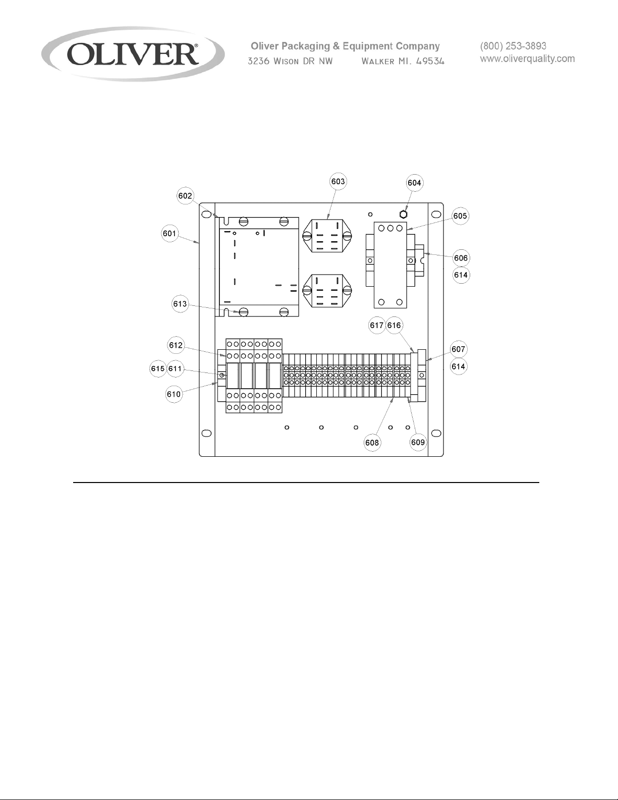
ELECTRICAL BOX REPLACEMENT PARTS LIST
NOTE: SEE THE MECHANICAL LIST FOR ELECTRICAL PARTS NOT ASSOCIATED WITH THE
ELECTRICAL BOX (PUSH BUTTONS, CABLES, LIMIT SWITCHES, MOTOR, ET C.)
BACK PLANE ASSEMBLY VIEW (INTERNAL):
ITEM NO PART DESCRIPTION PART NUMBER QUANITY
601 PLATE, ELECTRICAL BACK PLANE 1908-0348 1
602 DC DRIVE AND POTENTIOMETER ASSY 1908-0351 1
603 RELAY, 30A 2 POLE 1 20/250 VAC 5749-8034 2
604 SCREW, #10-24 GROUND 5841-1052 7
605 POWER SUPPLY, 24VDC 60W 5746-5305 1
606 RAIL, 2.5” DIN 1908-0350 1
607 RAIL, 9” DIN 1908-0349 1
608 BARRIER-END TERM. BLOCK 5770-7474 5
609 BLOCK, TERMINAL DIN MNT. 5770-7472 23
610 ANCHOR-END TERM. BLOCK 5770-7475 4
4- 1908S20077
For Service Parts Call 800-253-3893
1
Page 66
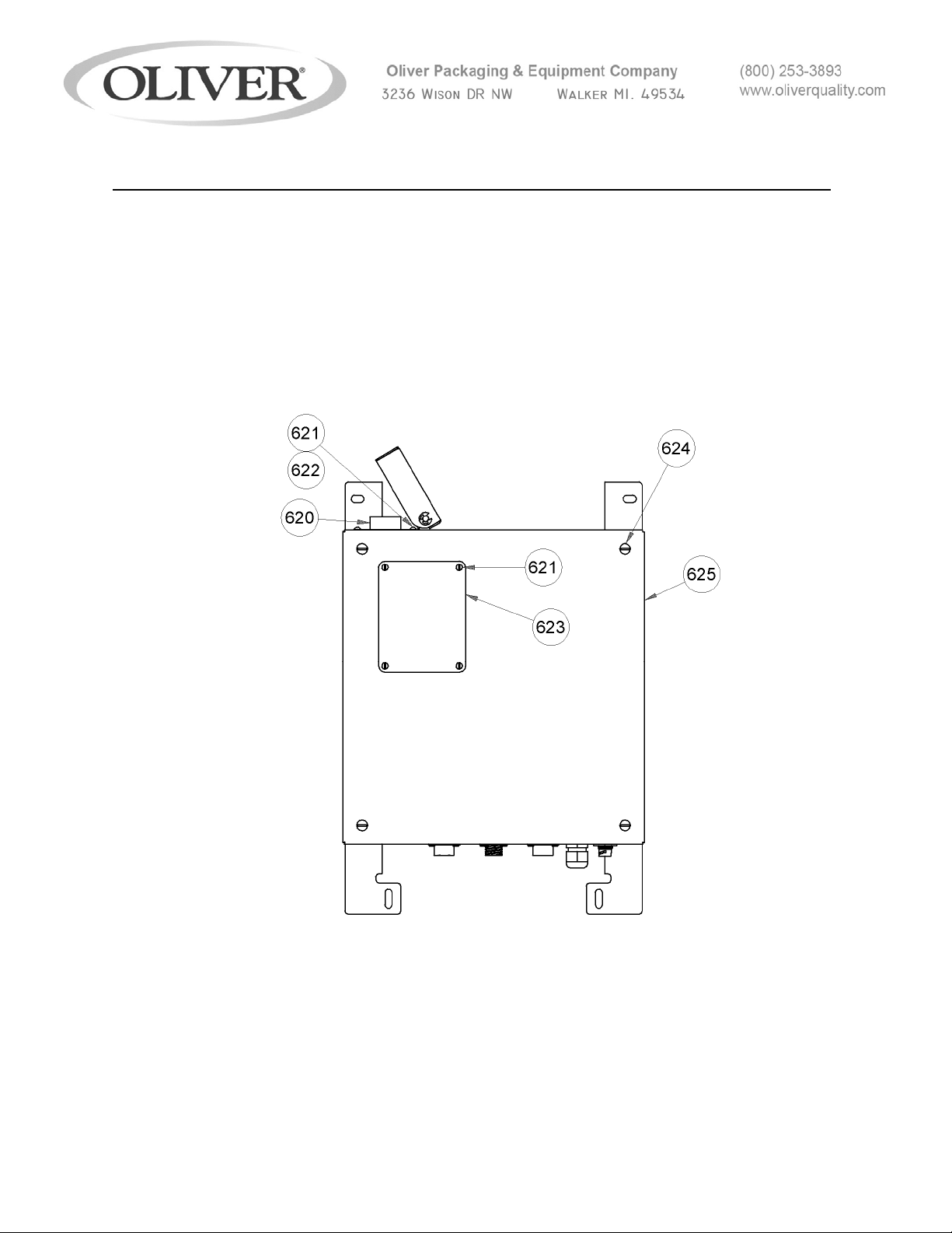
ELECTRICAL BOX REPLACEMENT PARTS LIST
ITEM NO PART DESCRIPTION PART NUMBER QUANITY
611 RELAY, DPDT 8A 24VDC 5749-5674 4
612 SOCKET- 8 PIN 5770-2832 4
613 SCREW, #8-32 X 3/8 STST 5843-5372 8
614 SCREW, #10-24 X 3/8 STST 5843-5384 8
615 CLIP, RELAY HOLD-DOWN 5749-5697 4
BOX FRONT VIEW:
620 KNOB KIT 6309-6035 1
621 SCREW - RND HD #6-32 X 1/4 STST 5843-5210 8
622 WASHER, #6 LOCK STST 5851-9353 4
623 WINDOW, CONTROL BOX 5500-5343 1
624 SCREW, TRUSS HD #10-24 X 1/2 STST 5843-5385 4
625 COVER, ELECTRICAL BOX 1908-0415 1
For Service Parts Call 800-253-3893
4- 1908S20077
2
Page 67
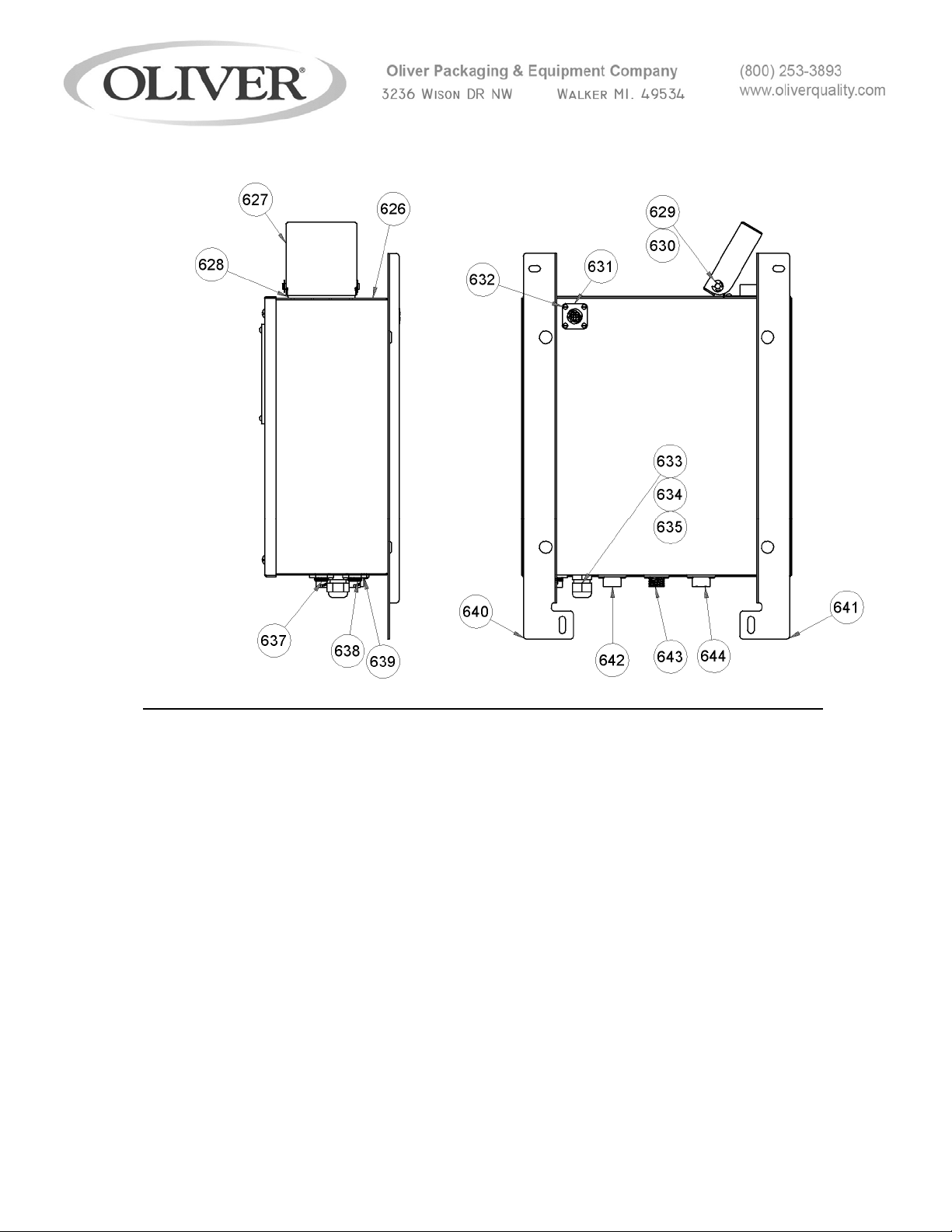
ELECTRICAL BOX REPLACEMENT PARTS LIST
BOX SIDE AND BACK VIEW:
ITEM NO PART DESCRIPTION PART NUMBER QUANITY
626 BOX, ELECTRICAL 1908-0413 1
627 COVER, POTENTIOMETER GUARD 1908-0357 1
628 BASE, POTIOMETER GUARD 1908-0356 1
629 ROD, POTENTIOMETER GUARD 1908-0358 1
630 RING, RETAINING 1/4” STST 5840-1273 2
631 RECEPTACLE, HEATER 1908-0399 1
632 SCREW, PAN HD 4-40 X 3/16 STST 5843-5520 16
633 ENTRY/ SW. MOD. 1 POLE W/ LIGHT 5746-7910 1
634 SCREW, F.H. #4-40 X 3/8 STST 5843-5022 2
For Service Parts Call 800-253-3893
4- 1908S20077
3
Page 68

ITEM NO PART DESCRIPTION PART NUMBER QUANITY
635 FUSE DRAWER W/ SHORTING BAR 5746-7950 1
636 FUSE, 10A 5725-9974 1
637 RECEPTACLE, SAFETY INTERLOCK 1 1908-0395 1
638 RECEPTACLE, SAFETY INTERLOCK 2 1908-0396 1
639 NUT, BRASS JAMB 5/8-24 UNEF 5832-0619 2
640 BRACKET, E-BOX MNT R.H. 1908-0414-0001 1
641 BRACKET, E-BOX MNT L.H. 1908-0414-0002 1
642 RECEPTACLE, R.H. SIDE 1908-0398 1
643 RECEPTACLE, MOTOR 1908-0401 1
644 RECEPTACLE, L.H. SIDE 1908-0400 1
For Service Parts Call 800-253-3893
4- 1908S20077
4
Page 69

This page intentionally left blank.
4- 1908S20077
5
Page 70
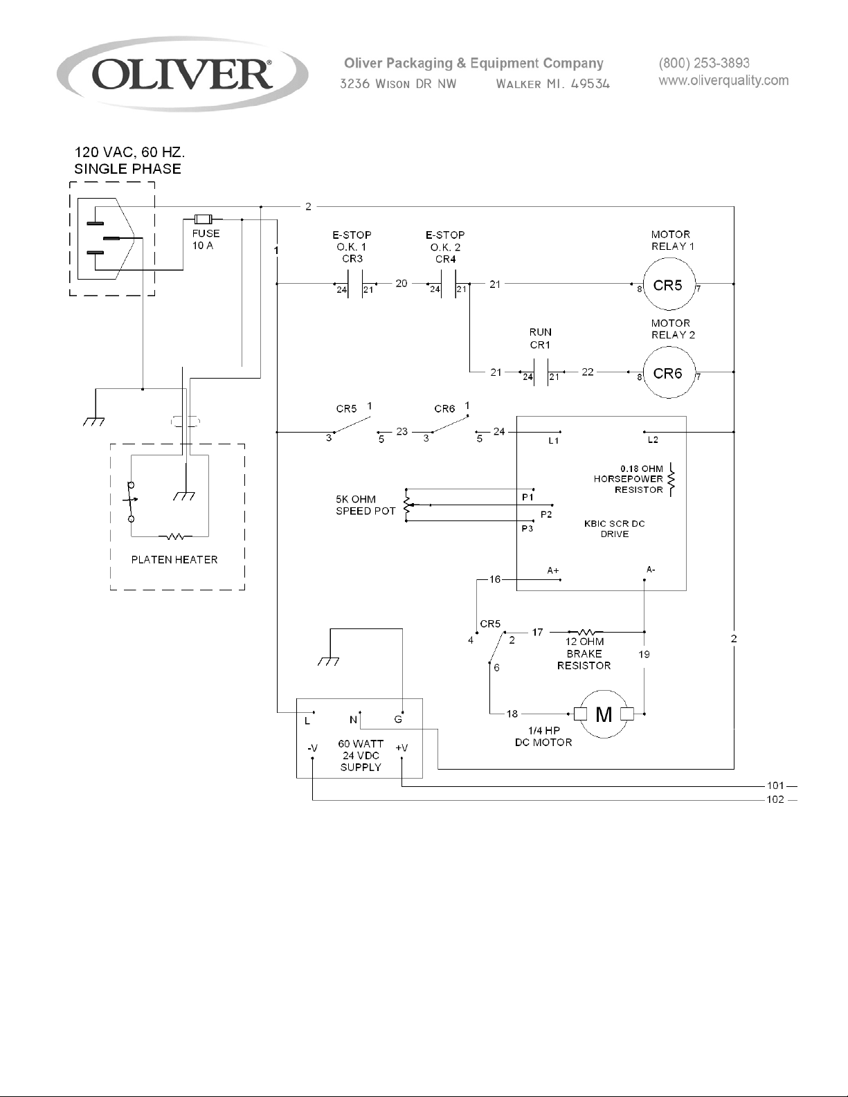
4- 1908S20077
6
Page 71
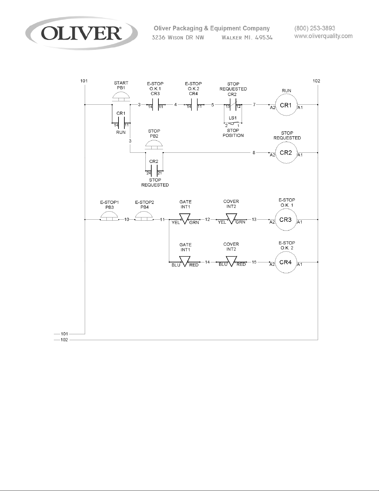
4- 1908S20077
7
Page 72

WARRANTY
PARTS
Oliver Packaging & Equipment Company warrants that if any part of the equipment (other
than a part not manufactured by Oliver Packaging & Equipment) proves to be defective (as
defined below) within one year after shipment, and if Buyer returns the defective part to
Oliver Packaging & Equipment within one year, Freight Prepaid to Oliver Packaging &
Equipment’s plant in Grand Rapids, MI, then Oliver Packaging & Equipment, shall, at Oliver
Packaging & Equipment’s option, either repair or replace the defective part, at Oliver
Packaging & Equipment’s expense.
LABOR
Oliver Packaging & Equipment further warrants that equipment properly installed in
accordance with our special instructions, which proves to be defective in material or
workmanship under normal use within one (1) year from installation or one (1) year and
three (3) months from actual shipment date, whichever date comes first, will be repaired by
Oliver Packaging & Equipment or an Oliver Packaging & Equipment Authorized Service
Dealer, in accordance with Oliver Packaging & Equipment’s published Service Schedule.
For purposes of this warranty, a defective part or defective equipment is a part or equipment
which is found by Oliver Packaging & Equipment to have been defective in materials
workmanship, if the defect materially impairs the value of the equipment to Buyer. Oliver
Packaging & Equipment has no obligation as to parts or components not manufactured by
Oliver Packaging & Equipment, but Oliver Packaging & Equipment assigns to Buyer any
warranties made to Oliver Packaging & Equipment by the manufacturer thereof.
This warranty does not apply to:
1. Damage caused by shipping or accident.
2. Damage resulting from improper installation or alteration.
3. Equipment misused, abused, altered, not maintained on a regular basis, operated
carelessly, or used in abnormal conditions.
4. Equipment used in conjunction with products of other manufacturers unless such use is
approved by Oliver Packaging & Equipment in writing.
5. Periodic maintenance of equipment, including but not limited to lubrication, replacement
of wear items, and other adjustments required due to installation, set up, or normal wear.
6. Losses or damage resulting from malfunction.
The foregoing warranty is in lieu of all other warranties expressed or implied AND OLIVER
PACKAGING & EQUIPMENT MAKES NO WARRANTY OF MERCHANTABILITY OR
FITNESS FOR PURPOSE REGARDING THE EQUIPMENT COVERED BY THIS
WARRANTY. Oliver Packaging & Equipment neither assumes nor authorizes any person to
assume for it any other obligations or liability in connection with said equipment. OLIVER
PACKAGING & EQUIPMENT SHALL NOT BE LIABLE FOR LOSS OF TIME,
INCONVENIENCE, COMMERCIAL LOSS, INCIDENTAL OR CONSEQUENTIAL
DAMAGES.
GEN 050816
Page 73

WARRANTY PROCEDURE
1. If a problem should occur, either the dealer or the end user must contact the Customer
Service Department and explain the problem.
2. The Customer Service Manager will determine if the warranty will apply to this particular
problem.
3. If the Customer Service Manager approves, a Work Authorization Number will be
generated, and the appropriate service agency will perform the service.
4. The service dealer will then complete an invoice and send it to the Customer Service
Department at Oliver Packaging & Equipment Company.
5. The Customer Service Manager of Oliver Packaging & Equipment Company will review
the invoice and returned parts, if applicable, and approve for payment.
GEN 050817
Page 74

RETURNED PARTS POLICY
This policy applies to all parts returned to the factory whether for warranted credit,
replacement, repair or re-stocking.
Oliver Packaging & Equipment Company requires that the customer obtain a Return
Material Authorization (RMA) number before returning any part. This number should appear
on the shipping label and inside the shipping carton as well. All parts are to be returned
prepaid. Following this procedure will insure prompt handling of all returned parts.
To obtain an RMA number contact the Repair Parts Deptartment toll free at (800) 253-3893.
Parts returned for re-stocking are subject to a RE-STOCKING CHARGE.
Thank you for your cooperation,
Repair Parts Manager
Oliver Packaging & Equipment Company
GEN 050818
 Loading...